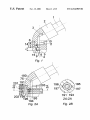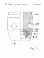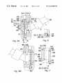
1
US006314985B1
(12) United States Patent
van der Blom
(10) Patent N0.:
(45) Date of Patent:
(54) VALVE CONNECTOR
(75) Inventor:
Nicolaas van der Blom, Birkerod (DK)
(73) Assignee: NVB International, Birkerod (DK)
(*)
Notice:
Subject to any disclaimer, the term of this
patent is extended or adjusted under 35
U.S.C. 154(b) by 0 days.
(21) Appl. N0.: 08/837,505
(22) Filed:
Apr. 18, 1997
Related US. Application Data
(63) Continuation-in-part of application No. PCT/DK96/OOO55,
?led on Feb. 2, 1996.
(30)
Foreign Application Priority Data
Feb. 3, 1995
Sep. 12, 1995
(51)
(52)
(58)
(DK) ................................................. .. 0125/95
(GB) ................................................ .. 9518558
Int. Cl.7 ................................................... .. F16K 15/20
US. Cl. ........................................... .. 137/231; 137/223
Field of Search ................................... .. 137/223, 231;
152/415; 251/1494; 285/148.23
Nov. 13, 2001
10/1987 (EP).
4/1991 (FR).
231992
872246
977139
1599304
2304844
WO 84/02968
W092/22448
4/1925
7/1961
12/1964
9/1981
3/1997
8/1984
12/1992
(GB).
(GB).
(GB).
(GB).
(GB).
(WO).
(W0).
W0 96/ 10903
WO 97/43570
4/1996 (WO) .
11/1997 (W0) .
Primary Examiner—John Rivell
(74) Attorney, Agent, or Firm—Price and Gess
(57)
ABSTRACT
By a universal valve connector for in?ation valves of vehicle
types (Sclaverand, Dunlop-Woods, or Schrader), Whose con
nector consists of a connector housing (368), Which partly is
connected to a pressure source, preferably a hand or foot
pump, and Which partly has a coupling hold (5) With a
diameter corresponding to the diameter of the valve, Which
is to be connected, Where the coupling hole is equipped With
a securing means for securing on the valve, plus a sealing
means against valves of different siZes. This is achieved by
the sealing means (366) being mounted coaxially in the
connector housing (368) and being established on at least
tWo parallel, separate levels, having the centre line (4) of the
References Cited
connector housing (368), Which is coaxial to the centre line
of the valve, as its normal, Where the minor diameters of the
U.S. PATENT DOCUMENTS
sealing means approximately correspond to the major diam
(56)
1,492,838 *
5/1924 Dilweg ........................... .. 137/231 X
1,850,111
3/1932 Kelsey .
2,025,067
12/1935 Miller.
2,257,498 *
2,489,397
2,685,906
0240 660
2 653 523
US 6,314,985 B1
9/1941
Hansen ............................... .. 137/231
11/1949 Brummer.
8/1954 Williams.
(List continued on next page.)
FOREIGN PATENT DOCUMENTS
eter of the current valve dimensions, on Which the connector
is mounted When used, that the sealing means (366), closest
to the opening (8) of the coupling hole (5) in the connector
housing (368) has the biggest minor diameter, While the
sealing means (366) farthest from the opening (8) of the
coupling hole in the connector housing (368) has the small
est minor diameter, and diameters betWeen the extremes are
lying corresponding separate distance betWeen these
extremes. The valve connector has the possibility of auto
matically adjust itself to the valve in question and if needed
25 44 555
3819771
196 01 952
7/1977 (DE) .
7/1989 (DE) .
A1
0125/95
7/1997 (DE).
8/1996 (DK).
to activate the central core of a Schrader valve. Also, it is
possible to use the connector With existing pumps.
1 Claim, 15 Drawing Sheets
US 6,314,985 B1
Page 2
US. PATENT DOCUMENTS
4,932,451
6/1990 Williams et a1. .
4,932,849
6/1990 Scheffer.
9/1955 Knasko .............................. .. 137/231
479387272
7/1990 Sandy’ Jr_ et aL _
2,976,906
3/1961 KamI_n_9ta1--
5,012,954
5/1991 Will ................................ .. 152/415X
3,249,144
5/1966 Dobnkln -
5,094,263
3/1992 Hurrell, 11 et a1. .
576457100
5762095
577787923
7/1997 Chuang et a1_ _
6/1998 Gapinski et a1_ _
7/1998 Marston _
2,716,998 *
3,926,205 * 12/1975 Gourlet .............................. .. 137/223
4,088,147 * 5/1978 Krechel et a1. .................... .. 137/223
4,165,760
8/1979 Guenthler .
4,489,855
4,611,828 *
12/1984 Boetger .
9/1986
Brunet ............................ .. 152/415 X
4,662,412
5/1987 Swallert .
4,712,812 * 12/1987 Weir, III ....................... .. 285/148.23
577857076
578197781
7/1998 You _
10/1998 Wu _
* cited by examiner
U.S. Patent
Nov. 13, 2001
Sheet 1 0f 15
US 6,314,985 B1
U.S. Patent
Nov. 13, 2001
Sheet 2 0f 15
US 6,314,985 B1
341
.1¢////
l
340
U.S. Patent
Nov. 13, 2001
Sheet 3 0f 15
52
US 6,314,985 B1
Fig. 4B
U.S. Patent
Nov. 13, 2001
Sheet 4 0f 15
US 6,314,985 B1
5A.1 5A.1
5A.2-5A.2
Fig. 7
U.S. Patent
Nov. 13, 2001
Sheet50f15
US 6,314,985 B1
i
A
l
307/
l
l
504%
\\ -
li. 7 k
305
§H
k;
l/
505
\_,3Q2
308
309
y/ 31 1
/
|
_%
l
I" %
%
/31O
//
U.S. Patent
Nov. 13, 2001
Sheet 7 0f 15
US 6,314,985 B1
517
304
505
316’
Fig.1O
U.S. Patent
Ti
Nov. 13, 2001
Sheet 9 0f 15
12A-12A, 125-125
Fig. 120
US 6,314,985 B1
U.S. Patent
Nov. 13, 2001
Sheet 10 0f 15
Fig. 125
US 6,314,985 B1
U.S. Patent
Nov. 13, 2001
Sheet 11 0f 15
US 6,314,985 B1
Fig. 13
U.S. Patent
// .
Nov. 13, 2001
Sheet 13 0f 15
US 6,314,985 B1
U.S. Patent
Nov. 13, 2001
Sheet 14 0f 15
I
Fig.
US 6,314,985 B1
U.S. Patent
Nov. 13, 2001
Sheet 15 0f 15
F
Fig. 17
US 6,314,985 B1
US 6,314,985 B1
1
2
VALVE CONNECTOR
also that the bushing (26) must be mounted again before
connecting to a Dunlop-Woods or Sclaverand valve. Also in
this case loose parts are used. They can disappear and loosen
This is a Continuation-in-Part of PCT/DK96/00055
When used, if the pump hose is turned, resulting in an untight
application ?led Feb. 2, 1996.
connection.
TECHNICAL FIELD
From DE-B 38 19 771, an universal connector on a
The invention concerns a valve connector for in?ation
through varying valves of vehicle types.
For reasons of clarity, some of the standards used Will be
cited. In the ISO standard No. 10475:1992(E). thread for
tyre in?ation valves of vehicles is described. The most used
threads are designated 5V2 (DIN: Vg 5,2), Which has a
10
handpump With tWo coupling holes is knoWn: one for
Dunlop-Woods and Sclaverand valves and one for Schrader
valves of Which the core pin is opened mechanically. The
disadvantage of this Wave of coupling is ?rstly, that it cannot
be fastened to a valve and secondly, that it can only be used
in a certain position. Where the coupling hole is turned
almost vertically upWards, and ?nally that the user has to
?nd out Which of the tWo holes to use for the valve in
nominal diameter of 5.2 mm and a pitch of 1.058 mm, and
question. This prior art has. therefore, no interest, When it is
8V1 (DIN: Va 8), Which has a nominal diameter of 7.7 mm
15
essential, that the user can use the coupling Without studying
and a pitch of 0.794 mm respectively. These thread types are
the type of valve, the user instructions. and decide Which
used in the valve types of Dunlop-Woods, Sclaverand or
type of valve should be used and thereafter turn the Wheel
Schrader. The last mentioned valve type is frequently used
With the valve to a cor rect, upright position for the valve
on common cars. Where a spring-loaded pin head in the
valve core must be kept doWn in preparation of the passage
of air, While pumping a tyre. For this purpose, the valve
coupling in question.
20
connector must be equipped With suitable means Which can
serve this aim. Moreover, suitable means, eg a contra valve
or the like, must be used to ensure a that loss of air is avoided
When activating the valve core pin. The Sclaverand valve
has—just like the Dunlop-Woods valve—the distinctive
character that its core pin is solely opened by air pressure.
The necessary air pressure for opening a Sclaverand valve is
up to 16 bar, and the valve is mostly used in connection With
high-pressure tyres With a pressure of up to 16 bar. The
opening pressure for the Dunlop-Woods valve is approXi
against pipes Without threads, and the aXial displacement of
25
30
It is commonly knoWn from mechanical engineering, that
corresponding screW, ie T §0,8><Dn. This rule of thumb is
used for highly-loaded constructions, Where the thread is
apparently, does not exist in the patent literature, is of the
35
different diameter and length, ?tting on 5V2 , and 8V1
centre line of the holes it is possible to mount a means,
Which can open the core pin of a Schrader valve. The
40
Well-knoWn valve connectors (e.g. GB-B-977,139) can
only be connected to to the Dunlop-Woods valve type and/or
the Sclaverand valve type, or the Schrader valve type.
45
coupling place for connecting the valve is alWays positioned
50
Which mechanically opens the Schrader valve has to be
turned in the above-mentioned operation. This is a problem
for the ordinary user, as both means must be positioned
correctly in relation to each other in order to be able to
stem by means of a lever, Which aXially compresses the
closest to the opening of the coupling hole. Also, the pin
rubber cylinder. Consequently, the rubber cylinder is
squeeZed radially against the stem. With reference to differ
ent valve diameters, it is necessary that auXiliary equipment
or increase the internal diameter in advance to ensure the
establishment of a connection from the valve connector to
connect the coupling to a valve: combinatorily, there are to
four possibilities to select from, Which can only be done
correctly if a user manual is available. Apart from that, the
other valve diameters. Loose parts can disappear and can be
loosened When used, if the pump hose is turned, so that the
above-mentioned means can be lost. loosened or disappear
55
connector type is that the user has to apply much strength
When using the lever. It is necessary to use both hands to
139 a valve connector operated by a lever cam is knoWn.
60
sponding to 8V1 also keeps the bushing (26) in position. The
bushing (26) has an internal thread (30) corresponding to
5V2 for Sclaverand or Dunlop-Woods valves. The core pin
of the Schrader valve is opened mechanically by means of
a stationary pin indicated With (12). The disadvantage of this
connector type is that the bushing (26) With a 5V2 thread has
to be removed before connecting to a Schrader valve, and
in the said operation.
From WO-A-92/22448 it is knoWn to provide a sealing
means, Which is placed in a single level, and from GB-B-977
stabiliZe the (dis)connection.
GB-B-15 99 304 shoWs a universal valve connector Which
can be screWed on all valve types. The thread (4) corre
disadvantage of coupling is partly that both hands must be
used to stabiliZe the (dis)-connection of the relevant valve
types and partly that the rubber cylinder must be taken out
of the housing and turned upside doWn to make connection
to valves With different thread types possible, so that the
A Well-knoWn connector for a Schrader valve is of the
connection is no longer air-tight. The disadvantage of this
304. This rubber cylinder consists of tWo adjacent parts of
threads, respectively. Axially, proXimally staggered on the
BACKGROUND OF THE INVENTION
(nut 6) is screWed onto or out of the valve thread to reduce
against the noZZles Without threads. Using a threaded tube in
such a gasket Would destroy the gasket after feW connec
tions.
Another Well-knoWn universal valve type, Which,
same type as the one of the above mentioned GB-B-15 99
fastened With a Wrench.
type, Where a rubber cylinder is tightly squeeZed against the
each sealing is not decisive. This kind of coupling is meant
for a tank ?lling device. The gaskets used for sealing the
adaptor are basically mushroom-shaped With the stem of the
mushroom arranged betWeen trapeZoidal Walls in the
adaptor, thereby leaving a semi-circular sealing to tighten
mately 4 bar, Which ensures that it is easier to open.
When connecting a nut to a thread the aXial length of the
thread TN for a nut N is §0,8>< the outer diameter DN of the
From US. Pat. No. 2,025,067 a coupling is knoWn, Where
tubes of different diameters can be coupled to matching
diameters in a tube. This prior art is intended for tightening
65
Common to both prior art references is that they can only be
used together With a Schrader valve, and that neither
Sclaverand type nor Dunlop-Woods type valves can be
served by this type of connector, as the sealing means only
shoW one diameter ?tting eg the Schrader valve.
THE OBJECT OF THE INVENTION
In?ating a tyre is a problem to many people, especially if
the tyres have different valve types, and only one pump has
US 6,314,985 B1
3
4
to be used. This is the case in most house-holds. The aim of
the invention is to provide a valve connector Which ?ts on
all current valve types, Which is easy to operate, is
of the threads are removed thereby forming tWo parallel
secants on each side of the Sclaverand type valve, a further
development of the inner bushing is suggested, Whereby the
economical, and Which has the possibility of automatically
adjusts itself to the valve in question. Also, it should be
inner bushing is running in an undercut grove in the valve
housing. Such Sclaverand type valve can not tighten against
the sealing means, and the pressuriZed air Will try to escape
possible to use the connector With existing pumps.
According to the invention this task is solved by means of
through the secant openings. By running in the undercut
grove the bushing Will tighten against this When mounting
the provisions in the characterising part of claim 1.
the valve connector on the valve.
By a connector for in?ation valves of vehicle tyres, Where
the connector consists of a housing connected to a pressure
source, preferably a hand or foot pump, and With a coupling
10
hole With a diameter corresponding to the diameter of the
valve to Which it is connected, Where the coupling hole is
equipped With a securing means for securing on the valve
and sealing means against valves of different siZes, the
invention is provided by the fact that the sealing means are
sealing means in a Well-knoWn Way consist of the bushing
15
of a deformable material positioned in the housing, prefer
ably a rubber type material shaped like a “H”, and that a
positioned coaxially in the housing behind the coupling hole
piston is mounted proximally to the valve and the rubber
and are established in at least tWo parallel discrete levels
With the centre line of the housing as their normal, Where the
bushing Which has tWo extremes to establish an axial
compression and release of the rubber bushing, and also a
lever for activating the piston, Where the axis of the lever is
placed perpendicularly to the centre line and concentrical
With this, and that the lever for activating the piston is turned
sealing means’ inner diameter approximately correspond to
the outer diameter of the current valve siZe to Which the
coupling is connected, When used, that the sealing means
Which is closest to the opening of the coupling hole in the
housing has the largest inner diameter, Whereas the sealing
means farthest from the opening of the coupling hole in the
housing has the smallest inner diameter, and the diameters
In connection With the (dis)connection With only one hand
the connector is provided by means of temporary thread, i.e.
created by squeeZing eg a rubber cylinder against the
existing valve thread of Which the securing means and
25
betWeen the extremes are in corresponding discrete dis
tances betWeen these extremes. The coupling place on a
from a position forming an angle III With the centre line to
a position almost perpendicular to the centre line, Where a
locking means of the lever is Working together With a
corresponding locking means of the housing, Whereby the
locking means of to the lever, as an example, is provided in
the construction of the lever. In a special advantageous
valve, Which is to be connected, is positioned against a
sealing surface on the sealing means in the coupling hole of
the concerned valve. The connector has only one coupling
embodiment a reaction arm is applied to absorb the reaction
forces originating from the movement of the lever arm
hole. The use of it is therefore simple, even Without a user
betWeen the tWo positions. This measure ensures a reliable
manual. and loose nipples are super?uous. Therefore, a
connection can alWays be established in only one operation.
In an appropriate embodiment of the invention, it is
suggested that the securing means is a rotational bushing
mounted on the housing, Which is equipped With a thread in
securing and a simple operation.
With this embodiment of the connector, it is possible to
mount same using just one hand, as the lever is taken doWn
35
and the reaction arm parallel to the hose connection on the
connector housing. By this action the piston is pressed
against the rubber bushing, Which is tightly squeeZed radi
ally against the concerned valve.
the coupling hole, Which ?ts on the respective valves, and
Which is sealed With the sealing means against the connector
housing, Which is farthest from the coupling hole in the
connector housing The connector can be positioned here on
the valve With an airtight connection. Which does not
In an improved embodiment of the valve connector, the
rubber bushing is provided With at the least one external
V-shaped incision in the circumference perpendicular to the
center axis close to those parts squeeZing against the threads
of the valve. Through such incisions the rubber bushing is
become untight, When the connected hose is turned. In
addition, mounting is quickly accomplished Without apply
ing signi?cant strength. (Dis)-Connecting of the coupling
can be done using only one hand.
To reduce the Wear of the gasket seal surface in the
connector housing and also to reduce the force by means of
to its locking position by just a simple squeeZing of the lever
45
predetermined to excerpt the largest radial force against the
thread exactly Where the incisions are and the user of the
valve connector Will experience a soft Working lever arm. In
Which the rotational bushing has to be turned, and further
order to support this purpose further and securing the valve
more to ensure a reliable sealing against valves With 5V2
connector on the valve even under high pressures it is
thread, a still more appropriate embodiment suggests that
the innermost thread is provided by a bushing With a 5V2
suggested, that a preferably torroidal shaped ring is arranged
in the incisions, thereby stressing the excerted radial forces.
thread, Where the bushing is embedded and—slightly—
axially sliding in a taper milling in the rotational coupling
bushing and is coupled rotational-free to the coupling bush
bending-moment-free (dis)-connection as the valve may not
ing by means of a set of ribs, Which are distributed around
the bushing circumference, and Which are geared into cor
The embodiment With the lever arm is designated: a
carry any bending-moment by the (dis)-connection. Con
55
responding grooves in the coupling bushing, and that the
sealing means rests on a stepped milling. This ensures that
frictional forces do not occur betWeen the gasket seal and the
coupling bushing during the main part of its fastening and
unscreWing, Whereas the coupling bushing is pulling the
connector housing and its gasket seal against the valve When
tightening Tightening occurs against the core of the valve
thread and is stabiliZed as a result of the reduced radius of
the inner part of the gasket seal.
In order to be able to use the valve connector on a
Sclaverand type valve, Which is not standardiZed, i.e. some
65
nection to almost all valves is possible, as such connector
type might be able to open a core pin in such Schrader valve,
Which is opening at an air pressure of approximately 5—6 bar.
The air pressure in the pump hose is of the same magnitude
as When a high-pressure tyre provided With a Sclaverand
valve is in?ated. This is optimally achieved by using a
high-pressure hand or foot-operated bicycle pump. There are
core pin types Which cannot be opened by means of air
pressure of an ordinary bicycle pump (eg 10 bar max.).
Connecting can be done easily and comfortably in tWo Ways.
Either the last mentioned core type is being replaced With the
?rst mentioned one and the embodiments or the invention
Without a pin are being used as a connector, or the core
US 6,314,985 B1
5
6
can—according to an appropriate embodiment of the
The Schrader valve has the biggest major diameter of the
external thread (thread type ISO 4570/3 8V1, ISO
10475z1992-12V1 resp.) and the coupling place is closest to
the opening of the coupling hole. The Dunlop-Woods cores
invention—be opened by a pin placed in continuation of and
coaxially to the centre line of the connector housing, Which
is transported by axial shifting from a position farthest from
the valve (FIG. 4A) to activate the central pin head of the
core (FIG. 4B). By this embodiment the necessary pumping
and the Sclaverand valves have the same thread type, Where
the major diameter of the external thread (thread type ISO
4570/2 5V2) is smaller than the minor diameter of internal
thread 8V1. Therefore, it is possible that the Dunlop-Woods
force is considerably loWer. When a Schrader valve is to be
in?ated, because no air pressure is used for to opening the
valve. In?ation can therefore be done With an ordinary
core type and the Sclaverand valve type can pass both the
coupling place of 8V1 threads and 12V1 threads.
bicycle pump.
Consequently, the coupling place of the connecting of 5V2
As a means for automatic sliding the activating pin in the
housing from a passive to an active position, the activating
pin is constructed as a piston equipped With a suitable
securing means and a piston rod, Which can slide in is the
thread is farthest from the opening of the coupling hole. The
5V2 thread of the Dunlop-Woods core (both the type Which
is DIN normed and the type Which in daily language is called
the ‘ball valve’), is suf?ciently sticking out over the nut 8V1
cylinder shaped housing, and Which, Without any physical
Which is keeping the core to the stem and of Which the major
diameter is less than the minor diameter of the internal
load, is held in a sealing longitudinal position against the
cylinder Wall, so that the sliding of the piston after the
thread for the 12V1 thread in the bushing. There is,
therefore, enough space for at least tWo thread types each
With a corresponding seal ring. The same applies for the
connection of the valve connector occurs by means of the
compressed air Which is transported from the pressure
source, and so that the piston in the position farthest from the
Wheel valve seals less than 100% against the cylinder Wall.
squeeZing connections, according to the invention, Where
the connector is squeeZed to form a temporary thread. The
said 8V1 nut cannot pass the coupling place of the Schrader
valve. That is due to the fact that the major diameter of the
With a valve connector according to claim 1 equipped
With such automatic sliding activating pin it is possible to
mount the valve connector equipped With a valve to a
compressor hose, Which can be available to the public
knoWn. eg from bicycle shops, etc. There, it is not neces
25
said nut is bigger than the diameter of the biggest hole in the
rubber cylinder (a major diameter of external thread 8V1).
The beginning of the coupling place of the 5V2 thread is at
distance a from the opening of the coupling hole. As the load
sary to fasten the valve connector to the valve, as the user
excerts the pressure necessary to secure an airtight connec
on the connection is loW, it is not necessary to use the entire
tion.
With such valve connector, in?ating tyres Without the user
length of the internal thread, as generally accepted rules say
0.8x of the siZe of the coupled external thread. This rule is
having to identify the valve type and functioning has
become possible. The operation conveniency has also
based on mechanical constructions Which are high-loaded
increased signi?cantly, and it Will noW be easier for the user
to in?ate the tyre to the correct pressure, Which in general
eases the driving and reduces tyre abrasion. At the same
time, a contra valve function is added to the Schrader valves
in that the valve only opens the core of the Schrader valve
When suf?cient air pressure is fed from the pressure source
and air thus cannot escape from the tyre during in?ation.
In an appropriate embodiment of the valve connector
possible that the coupling place of the 5V2 thread is behind
the coupling place of the 8V1 thread.
and Where the thread is fastened by a Wrench. It is therefore
35
The invention can exist in a number of embodiments
Which Will appear from from the dependent claims.
SPECIFICATION OF THE DRAWINGS
The invention is explained in details beloW by means of
draWings. The draWing shoWs in:
FIG. 1 the universal connector in the ?rst embodiment
connected to the hose of a (high-pressure) foot pump, Where
according to the invention, it is suggested that the piston is
constructed With a central, axially sliding valve, Which is
elastically pressed to a closing position against the piston
the connector is screWed on the valve and a Schrader valve
top. This provides a Well-de?ned opening Zone, Which is not
type can be opened by air pressure;
in?uenced by abrasion in the piston guide, and the increas
45
ing opening of the core secures the passage of compressed
air from the pressure source as Well.
FIG. 2A the connector according to FIG. 1 in a second
embodiment Where the bushing With 5V2 thread and a
gasket sealing for Schrader can slide parallel to the centre
line;
As an example, the central, axially sliding valve on the
FIG. 2B a rendering details of the connector according to
piston can in a suitable Way be activated by the fact that the
piston valve is levered With a valve lever, Which reaches
FIG. 2A, (section 2A—2A);
eccentricity through the piston, and by the fact that a spring
betWeen the piston and its valve keeps the valve closed When
FIG. 3 the connector according to FIG. 2 in a third
embodiment designed to be used on a Sclaverand valve,
the piston does not in?uence the core in the Wheel valve.
Alternatively, the piston valve can be levered With a core
55
Which is not according to the ISO-standard;
FIGS. 4A, B universal connector according to FIG. 1 in
pin Which concentricly reaches axially through the piston,
a fourth embodiment Where the coupling is screWed on the
Where a spring leads it to a position distally from the piston.
It has thus become possible to provide the piston With a
reliable function Within the limits established by the ISO
standard, as the piston With the core pin automatically
adjusts its length to the limits of the valve in question.
valve, and a Schrader valve can be opened mechanically by
means of a pin, Where the pin feed mechanism is constructed
With a thread and Where the pin is shoWn in the top and
bottom position, respectively;
FIGS. 5A, B universal connector according to FIGS. 4A,
4B in a ?fth embodiment, Where the pin feed mechanism is
constructed With a big thread pitch, and Where the pin is
The latter embodiments ensure a safe functioning of the
valve lever, because it is enclosed and only in?uenced by
axially directed forces. Also, the bridge on the Schrader
valve can be used for activating the piston valve. Further, the
reaction forces from the piston is led to the air and not to the
mechanical constructions.
shoWn in the top and bottom position, respectively;
65
FIG. 6 a rendering of details of the connector according
to FIG. 5A (section 5A. 1—5A.2) and FIG. 5B, (section
5B—5B);