1
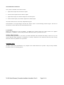
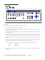
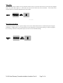
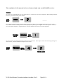
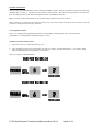
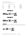
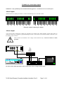
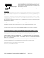
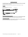
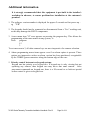
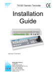
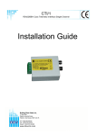
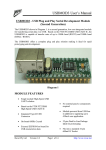
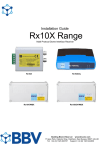
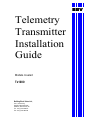
BBV
Telemetry
Transmitter
Installation
Guide
Models covered
Tx1000
Building Block Video Ltd.,
Unit 1, Avocet Way,
Diplocks Industrial Estate,
Hailsham, East Sussex, UK.
Tel: +44 (0)1323 842727
Fax: +44 (0)1323 842728
TRANSMITTER VARIANTS
The system is available in four main variants:
1.
Eight camera inputs and two monitor outputs.
2.
Sixteen camera inputs and two monitor outputs.
3.
Eight camera inputs, two monitor outputs and 16 alarm inputs.
4.
Sixteen camera inputs, two monitor outputs and 16 alarm inputs.
All variants allow the use of two fully independent keypads.
The transmitter is a two-part design: the base unit, which is wall- or rack-mounting; and the keypad. The two are
connected by a video cable and a bi-directional RS232 link.
UNPACKING
Inspect the packaging for signs of damage If damage has occurred, advise the carriers and/or the suppliers
immediately. Unpack the units carefully and check that all the items are present and correct.
SAFETY PRECAUTIONS
All normal safety precautions as laid down by British Standards and the Health and Safety at Work Act (or the
relevant National safety legislation if installing in a country outside the U.K.) should be observed, and servicing
should be referred to qualified service personnel.
INTRODUCTION
The BBV Tx1000 Series transmitters are very simple to use in multi-camera CCTV systems. They are easily installed
into either a new or an existing system.
Tx1000 SeriesTelemetry Transmitter Installation Handbook Rev-01
Page 2 of 14
1
ILLUSTRATION OF Tx1000 SYSTEM
Rx400DC
static camera
STATIC
Rx300M
Rx200
Rx100
static camera with lights/
wash/wipe
dome camera
4 local alarms
Rx200
simple AC panner
Rx400P
AC P/T Mitsubishi
CCD400 control
2 Aux.
Rx300
AC P/T Zoom/Focus
1 Aux.
High & Variable speed
P/T Zoom/Focus
16 Preset with 3 Aux.
8 Local alarms
AC P/T Zoom/Focus
16 Presets with 4 Aux.
Twisted Pair Telemetry.
Closed loop resistance < 300R
up the coax telemetry control up to 1Km CT125
video in - coax
Optional
Twisted Pair
alarm cable
Optional Alarm Package
Tx1000/8 or 16 Base Unit
TxLD
TxLD
Twin Twisted Pair
video out - coax
Optional TxLD link. Distance > 50M.
RS232 control Max distance - 50M
OptionalTxLD available for extended distances.
9V plug PSU
LENS
B B V
2
3
4
9
10
11
12
5
6
7
8
13
14
15
16
PROGRAM
IRIS
CAMERA
SEQ
PATROL
LENS
B B V
1000
1
PRESET
#
FOCUS
AUTOPAN
ZOO
M
1000
1
2
3
4
9
10
11
12
CAMERA
MONITOR
SEQ
B B V
6
7
8
13
14
15
16
PROGRAM
IRIS
SELECT
LENS
5
300
PATROL
PRESET
FOCUS
AUTOPAN
ZOO
M
SELECT
MONITOR
B B V
PAN + TILT
LENS
KEYBOARD 1
Tx1000 SeriesTelemetry Transmitter Installation Handbook Rev-01
#
300
PAN + TILT
OPTIONAL 2ND KEYBOARD
Page 3 of 14
1
LAYOUT OF THE BBV Tx1000 KEYPAD
Connections
Having mounted the base unit on the wall or in a rack, continue as follows:
1.
Connect the keypad to 9-pin d socket marked "Keypad 1".
2.
Connect a BNC cable from output M1 to the keypad, and connect the other keypad connection to Monitor 1.
Terminate the cable at the monitor.
3.
If the keypad is remotely sited from the base unit, connect the plug-mounted power supply to the keypad via the
2.1mm power connector.
4.
Connect either a second spot monitor (no keypad and no text), or the second keypad to Output 2. Note that even if
both keypads are local to the main unit, the second keypad must be powered from the plug-mounted transformer.
5.
Connect the BNC cables from the cameras/receivers to the upper BNC sockets in each row, marked "Camera
Inputs".
6.
Connect any other equipment requiring the camera video signals to the lower BNC sockets marked "Video Out".
Note that the action of connecting to the video-out socket removes the 75Ω termination.
7.
If the user relay terminals are being used, connect these to the LOW VOLTAGE equipment of your choice.
PIN 6
PIN 7
PIN 8
8.
normally closed
common
normally open
Apply power via the IEC connector and switch on. The power LED should flash and the monitors should show
Camera 1 inputs
Tx1000 SeriesTelemetry Transmitter Installation Handbook Rev-01
Page 4 of 14
1
Camera Selection
A camera may be selected onto the controlled monitor by pressing the relevant numbered key.
Monitor Selection
The monitor key has a red LED which is lit when the keypad is controlling the second monitor output. Pressing the
monitor key toggles between the main monitor and the second monitor.
Sequence Activation
Pressing the sequence key will start the sequence on the MAIN monitor. The on-screen display changes from CAM
XX to SEQ XX to indicate that the sequence is running. To stop the sequence, select a camera on the main monitor.
Programming the Sequence Order
Holding down the sequence key causes the sequence to run through the list of inputs at the rate of one per second,
allowing the operator to quickly determine which inputs are/are not in the sequence list. While the sequence key is
held down, any camera key pressed will toggle the inclusion or exclusion of the relevant input. When delivered, all
camera inputs are inluded in the sequence.
Altering the Sequence Delay
This is achieved by pressing the Program key, to gain access to the menu. Sequence delay time may be altered using
Option 9. The on-screen prompt "Seq Delay" appears, inviting the operator to enter a number from 1 to 16 for the
following values:
1
2
3
4
5
6
7
8
9
10
11
12
13
14
15
16
5 seconds
10 seconds
15 seconds
20 seconds
25 seconds
30 seconds
35 seconds
40 seconds
45 seconds
50 seconds
55 seconds
60 seconds
65 seconds
70 seconds
75 seconds
80 seconds
After entering the delay value, the screen clears.
The Triangular-Marked Key
This key activates a relay in the base unit. Pressing the key causes changover contacts to close; releasing the key
opens one set and closes the other. This key may be used by the installer to activate a panic record facility on a VCR,
or to activate a video printer, etc. These contacts are low-voltage, low-current only.
IMPORTANT: DO NOT CONNECT THESE CONTACTS TO MAINS POTENTIALS
Tx1000 SeriesTelemetry Transmitter Installation Handbook Rev-01
Page 5 of 14
1
KEYPAD FUNCTIONS
Pan and Tilt Action:
Press the relevant direction arrow(s)
Lens Action
There are six lens-function switches on the BBV Tx400
keypad. These are Iris Open, Iris Close, Focus Near, Focus
Far, Zoom In and Zoom Out. Press and hold the relevant
key until the desired picture is obtained. Note: If the key is
pressed and held for longer than one second, High Speed
Lens Action is activated. Inching is achieved by repeated
quick presses of the key.
Auxiliary Function Switches
There are four auxiliary function switches on the BBV Tx1000 keypad. These are Wash, Wipe, Autopan and Lights.
Their functions are as follows:
Wash
Wipe
Auto
Lights
-
Press and hold for washer motor to run
Latching output, press on/press off
Press, LED lights up and autopan motor starts. Pressing Left or Right stops Auto
Latching output, press on/press off
Tx1000 SeriesTelemetry Transmitter Installation Handbook Rev-01
Page 6 of 14
1
SELF TEST
To activate the self test feature for any particular camera reciever, first select that receiver, then press the Program
button and select Menu Option 2. The screen text will clear and Self Test will be activated . See the Rx Series
Telemetry Receiver Installation Handbook for more details.
------------
IRIS LEVEL PROGRAM
To preset the aperture of the iris, press Iris Open or Iris Close until the desired level is reached, then press Program
and Option 3. Note: There is a 15-second time-out, after reaching the correct aperture setting, in which to program
the iris setting. When this time period expires, the iris reverts to its default setting.
Tx1000 SeriesTelemetry Transmitter Installation Handbook Rev-01
Page 7 of 14
1
The remainder of this manual refers to features found only on the Rx400P receiver.
PRESETS
To select a pre-programmed preset, press the Preset key. On the screen, "Preset" will appear. While holding down the
Preset key, select the desired preset number.
------------
To programme a preset, first position the camera using the Up/Down and Left/Right arrows. Then set Zoom and
Focus. When satisfied with the position and the quality of the picture, press Program and select Option 1. When the
on-screen display changes to "Program Preset", enter the number of the preset you wish to program.
To erase a preset, press the Program key to gain access to the menu. Select Option 4 and when the display changes to
"Erase Preset", select the number of the preset to be erased.
Tx1000 SeriesTelemetry Transmitter Installation Handbook Rev-01
Page 8 of 14
1
PATROL SETTINGS
There are two patrol commands that can be started by the BBV Tx1000. They are activated by pressing the Patrol key
and either Key 1 or Key 2. All other keys are ignored. Their function is to enable a string of presets to be selected in
turn, switching between presets after a fixed period of time (nominally 30 seconds).
Note: Once the nominal time period of 30 seconds has been altered, it cannot revert back.
These patrols can be stopped at any time by pressing any of the four arrows on the Pan and Tilt control, when the
reciever on which patrol is running is selected.
To Programme a Patrol
There is no separate patrol-programming function with the BBV Tx1000 keypad. Once a preset has been
programmed, it is automatically included in Patrols 1 and 2.
To Remove a Preset from a Patrol
1.
Select the reciever on which the patrol is to run.
2.
Press Program to gain access to the menu, then press 5 to remove a preset from Patrol 1 or 6 to remove from
Patrol 2, followed by the preset number to be removed.
This key sequence is illustrated below.
Tx1000 SeriesTelemetry Transmitter Installation Handbook Rev-01
Page 9 of 14
1
To Programme a Time Period for a Patrol
First, determine the time delay required from the table below:
key 1
key 2
key 3
key 4
key 5
key 6
key 7
key 8
random, 0 to 100 seconds
12 seconds
24 seconds
36 seconds
48 seconds
60 seconds
72 seconds
84 seconds
key 9
key 10
key 11
key 12
key 13
key 14
key 15
key 16
96 seconds
108 seconds
120 seconds
132 seconds
144 seconds
156 seconds
168 seconds
180 seconds
SPARE OUTPUTS
There are four spare outputs, which are momentary-action, for use as relay drivers. They are activated by pressing
simultaneously the # key and one of the auxiliary keys. An on-screen display confirms which output has been
activated.
Tx1000 SeriesTelemetry Transmitter Installation Handbook Rev-01
Page 10 of 14
1
Tx1000 Series Alarm Input Option
WARNING: Only qualified persons should install this apparatus. It contains no user-serviceable parts.
Alarm Inputs
Alarms activate on opening of contacts. Connect each alarm pair to a volts free contact.
1
2
3
4
5
6
7
8
9
1
0
1
1
1
2
1
3
1
4
1
5
1
6
Normaly closed, opening for alarm.
Alarm output
A set of NO VOLT changeover contacts are provided as an output to the alarm package, closure takes place on
detection and they stay closed for a programmed length of time. The contacts are accessed via alarm contacts 2,3,4 on
the smaller green connector.
SET
COMMON
RESET
These contacts are suitable for low voltage control functions only! DO NOT connect to mains
potential
Expanded View
LENS
B B V
1000
1
2
3
4
9
10
11
12
5
6
7
8
13
14
15
16
PROGRAM
IRIS
CAMERA
SEQ
PATROL
PRESET
#
FOCUS
AUTOPAN
ZOOM
TIME LAPSE
SELECT
MONITOR
B B V
LENS
300
PAN + TILT
Do NOT connect mains potentials to these contacts they are low voltage contacts only!!
Tx1000 SeriesTelemetry Transmitter Installation Handbook Rev-01
Page 11 of 14
1
ALARM CONTACTS
Installer fitted keyswitch to
control alarm package
The alarm package may be enabled/disabled via a keyswitch fitted
across alarm contacts pins 1 and 2. When the switch is closed the alarm
package is disabled, opening the switch and the alarm package is active.
This may be used to control the alarm package, i.e. enabled at night
when the building is empty etc.
Note that cutting the switch cable will activate the alarm package.
Keyswitch
Action on alarm
Each alarm can be programmed to switch monitor 1 to display a specific camera and goto a pre-set position for that
camera. An alarm message is displayed on the screen and the alarm output relay closes for a programmed length of
time.
If the sequence is running then the alarm time is added to the sequence time and the sequence continues to run after
the alarm times out. If the sequence is not running the alarm message and selected camera remain on monitor 1 until
a manual camera selection.
The camera selected and the pre-set command issued is programmable via the keypad, press the program key and
follow the on screen commands.
The length of time the contacts close is also programmable. Press the program key and follow the instructions on the
screen
To disable the program key remove the shorting link from the small rectangular slot below monitor 2 output
To use the goto pre-set feature you must have fitted Rx400P or Rx400DC receivers and pre-set PTZ heads.
Alarms and the BBV Rx100 dome interface, Rx400DC high/variable speed DC receiver.
These receivers have 4 & 8 local alarm inputs respectively and a single normally closed relay output that opens
momentarily when a local alarm is activated. This output can be wired to an alarm input on the Tx1000.
A receiver local alarm will cause the relevant pre-set position to be automatically selected without the intervention of a
telemetry transmitter, see the receiver installation guide. If the transmitter also generates a goto pre-set command,
then the receiver’s goto pre-set will be overruled. To overcome this, alarm pre-set 16 now becomes a special that
disables a goto pre-set command.
If the local alarm feature of any receiver is used then set the alarm pre-set position to 16 from the Tx1000 menu.
The standard AC Rx400P receiver can be programmed to goto pre-set position 1-15 during an alarm.
If you require to call preset 16 then software is available from BBV.
If at all unsure, please call BBV for assistance.
Tx1000 SeriesTelemetry Transmitter Installation Handbook Rev-01
Page 12 of 14
1
TWISTED PAIR OPTION
The TWISTED PAIR option sends telemetry signals from the transmitter to the receiver. A video cable
connection is still required. The normal reason for using a twisted pair option is to connect to a non-cable
transmission system, fibre, microwave etc.
The twisted pair output option provides a 20mA compatible output. 1200 baud 8 data bits 1 stop bit.
Connections
Multi Camera Twisted pair connections
Vertical green connector on
rear of transmitter Tx1000
Grey connector on
receiver PCB pins 1 and 2
Note units will still work if cables reversed
Camera 2,3,4 etc
Video cables still required
470R
Fit 470R Resistor to suppress Telem signal
on static cameras
MIXED COAX AND TWISTED PAIR SYSTEMS
The Tx1000 series of transmitters copes automatically with a mixture of coax and twisted pair connected
receivers, directing the telemetry signal to the relevant interface. The only requirement is that the installer
should connect the twisted pair cable to the telemetry output corresponding to the video input.
TO SUPPRESS COAX SIGNAL
When it is required to remove the coax telemetry signal from a static camera, i.e. no telemetry required at
all, install a 470R resistor across the relevant twisted pair output contacts. Often fibre optic equipment
dislikes having a telemetry signal on its output, as it can upset the AGC.
Tx1000 SeriesTelemetry Transmitter Installation Handbook Rev-01
Page 13 of 14
1
Additional information
It is strongly recommended that this equipment is pre-built in the installer's
workshop in advance, to ensure problem-free installation at the customer's
premises.
1. The software version number is displayed for approx 2 seconds on first power up eg "VF"
2. The keypads should not be connected or disconnected from a "live" working unit,
as this may damage the RS232 components.
3. A new menu item "15" now appears on pressing the program key. This allows the
programming of the max camera in any system, ie
Press
program
15
3
To set max cam to 3, all other camera keys are now inoperative for camera selection.
4. Alarm programming menu items appear even if no alarm option is present. These
options are inoperative unless an alarm version has been purchased, recognisable
by the THREE green connectors along the bottom edge of the case.
5. Priority control between two keypad systems
Keypad one has priority over keypad two. If keypad one is only viewing but not
operating any camera, then keypad two may move that same camera. After
movement commands on keypad one, there is a 20-second or so lock-out period
before control is given to keypad two.
Tx1000 SeriesTelemetry Transmitter Installation Handbook Rev-01
Page 14 of 14
1