1
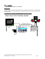
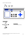
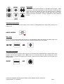
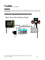
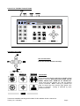
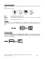
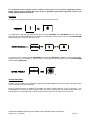
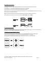
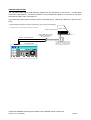
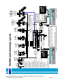
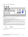
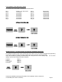
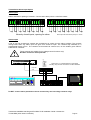
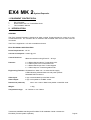
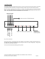
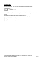
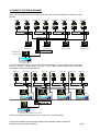
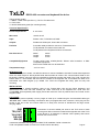
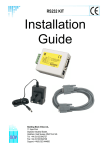
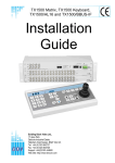
Telemetry
Transmitter
Installation
Guide
Models covered
Tx300
Page 3 (Simple, 1-2-1 controller)
Tx400 & Tx400DC
Page 7 (1-2-1 controller)
Tx1000 series MK2
Page 14 (8/16 camera matrix)
Tx1000 Keypad
Page 27 (Telemetry control keyboard for Tx1000 matrix)
Ex4 MK2
Page 28 (System expander – control 4 TX1000 from 1 keyboard)
TxLD MK2
Page 32 (RS232-RS422 converter)
Building Block Video Ltd.,
17 Apex Park,
Diplocks Industrial Estate,
Hailsham, East Sussex, BN27 3JU, UK.
Tel:+44 (0)1323 842727
Fax:+44 (0)1323 842728
Support:+44(0)1323 444600
www.bbvcctv.com
Tx300-400-1000MK2-1000 Keypad-Ex4 MK2-TxLD Installation Guide 12Jan05.doc
BBV
IMPORTANT
Please read the following points before servicing or installing.
Pre-installation Checks - It is recommended that the unit be bench-tested prior to installation on the site.
Safety During Installation or Servicing - Particular care should be taken to isolate the pan/tilt head in
order to prevent operation while engineering work is being carried out. In addition any ladder or other
means of working on the receiver MUST NOT rest on the pan/tilt head as it is possible for the head to move
when not expected.
Safety Check - Upon completion of any service or repairs to the unit, safety checks should be performed to
ensure that the unit is in proper operating condition.
Co-ax Grounding - If an outside cable system is connected to the unit, be sure the cable system is
grounded.
Adhere to Safety Standards - All normal safety precautions as laid down by British Standards and the
Health and Safety at Work Act should be observed.
WARNING - TO PREVENT DANGER OF FIRE OR SHOCK, DO NOT EXPOSE THE INTERNAL
COMPONENTS OF THIS EQUIPMENT TO RAIN OR MOISTURE.
Damage Requiring Service - Servicing by qualified personnel should be carried out under the following
conditions:
(a) When the power-supply cord or plug is damaged;
(b) If liquid has been spilled, or objects have fallen into, the unit;
(c) If the internal electronics of the unit have been exposed to rain or water;
(d) If the unit does not operate normally by following the operating instructions. Adjust only those
controls that are covered by the operating instructions, as improper adjustment of other controls may
result in damage and will often require extensive work by a qualified technician to restore the unit to
normal operation;
(e) If the unit has been dropped or the enclosure is damaged;
(f) If the unit exhibits a distinct change in performance. This indicates a need for service.
Replacement Parts - If replacement parts are required, ensure that only replacement parts recommended
by the product manufacturer are used.
Additional information
It is strongly recommended that this equipment is prebuilt in the installer's workshop in advance, to ensure
problem-free installation at the customer's premises.
Tx300
Simple 1-2-1 controller
INTRODUCTION
The BBV Tx300 is a very easy-to-use keypad for use in a single-camera CCTV system. It is easily installed
into either a new or an existing system simply by connecting a BNC input and output, or twisted wire pair
and a 9Vdc supply.
ILLUSTRATION OF TELEMETRY SYSTEM SHOWING LOCATION OF KEYPAD
Basic One-to-One Telemetry System
250M-RG59/ 500M-CT125
alternative-20mA twisted pair
75R Terminated
Monitor
B B V
1000
PROGR AM
IRIS
FOCUS
ZOOM
PAN + TILT
BBV Rx receiver
POWE
Tx300 Transmitter
9v PSU
POWE
Tx300-400-1000MK2-1000 Keypad-Ex4 MK2-TxLD Installation Guide 12Jan05.doc
Tx300 (simple 1-2-1 controller)
Page 3
LAYOUT OF THE BBV Tx300 KEYPAD
KEYPAD FUNCTIONS
Pan and Tilt Action:
Press the relevant direction arrow(s)
Tx300-400-1000MK2-1000 Keypad-Ex4 MK2-TxLD Installation Guide 12Jan05.doc
Tx300 (simple 1-2-1 controller)
Page 4
Lens Action
There are six lens-function switches on the BBV Tx300 keypad. These
are Iris Open, Iris Close, Focus Near, Focus Far, Zoom In and Zoom Out.
Press and hold the relevant key until the desired picture is obtained.
Note: If the key is pressed and held for longer than one second, High
Speed Lens Action is activated. Inching is achieved by quick presses of
the key.
Auxiliary Function Switch
There is only one auxiliary function switch on the Tx300; it is designated as the lights relay, press for on,
press for off.
LIGHTS CONTROL
SELF TEST
To run Self-Test, press Program and Focus Far. This activates the Self-Test routine in the BBV range of Rx
telemetry receivers. See the Telemetry Receiver Installation Handbook for more details.
IRIS LEVEL PROGRAM
To pre-set the aperture of the iris, press Iris Open or Iris Close until the desired level is reached, then press
Program and iris open together to set. Note: There is a 15-second time-out, after reaching the correct
aperture setting, in which to program the Iris setting. When this time period expires, the iris reverts to its
default setting.
IRIS SET
AND
Tx300-400-1000MK2-1000 Keypad-Ex4 MK2-TxLD Installation Guide 12Jan05.doc
Tx300 (simple 1-2-1 controller)
Page 5
RANDOM PAN – Rx300
The Rx300 telemetry receivers provide a random pan feature. During Random Pan operation, the camera is
randomly panned left or right for a random duration, paused for a random duration and then panned again.
This adds the affect that the camera is manually controlled. During random pan, the camera can be tilted to
the desired angle using the up/down buttons. Random pan is disabled by pressing either the pan right or
the pan left button.
TWISTED PAIR OUTPUT
The TWISTED PAIR output sends telemetry signals from the transmitter to the receiver. A video cable
connection is still required. The normal reason for using a twisted pair option is to connect to a non-cable
transmission system, fibre, microwave etc.
The twisted pair output option provides a 20mA compatible output. 1200 baud 8 data bits 1 stop bit, Even
parity.
Simple twisted pair telemetry when not practical to use upA coaxial cable is required to carry the video from the camera to the control
Section of Rx
Polarity not important at Rx.
Maximum cable resistance 330R
Tx300/400/400DC
If RF/Laser/Microwave etc. used
to extend link, 20mA input may
be polarity sensitive.
Grey connector on Rx PCB, Pins 1 &
2
If the Rx is over driven from the RF/
Laser/Microwave equipment, the error
LED will light. Connecting a 470R
resistor across Pin 1/2 cures
bl
B B V
1
2
3
4
5
6
7
8
PROGRAM
IRIS
PRESETS
#
FOCUS
LENS
AUTOPAN
ZOOM
PAN
& TILT
Tx300-400-1000MK2-1000 Keypad-Ex4 MK2-TxLD Installation Guide 12Jan05.doc
Tx300 (simple 1-2-1 controller)
Page 6
Tx400
1-2-1 controller
INTRODUCTION
The BBV Tx400 is a very easy-to-use keypad for use in a single-camera CCTV system. It is easily installed
into either a new or an existing system simply by connecting a BNC input and output, or twisted wire pair
and a 9-volt supply.
ILLUSTRATION OF TELEMETRY SYSTEM SHOWING LOCATION OF KEYPAD
Basic One-to-One Telemetry System
250M-RG59/ 500MCT125
alternative-20mA twisted pair
75R Terminated
Monitor
B B V
1
2
3
4
400
PROGR AM
IRIS
5
6
7
8
PRESETS
#
FOCUS
AUT OPAN
ZOOM
LENS
PAN + TILT
BBV Rx receiver
POWE
Tx400 Transmitter
9v PSU
POWE
Tx300-400-1000MK2-1000 Keypad-Ex4 MK2-TxLD Installation Guide 12Jan05.doc
Tx400 (1-2-1 controller)
Page 7
LAYOUT OF THE BBV Tx400 KEYPAD
KEYPAD FUNCTIONS
Pan and Tilt Action:
Press the relevant direction arrow(s)
Lens Action
There are six lens-function switches on the BBV Tx400
keypad. These are IRIS OPEN, IRIS CLOSE, FOCUS
NEAR, FOCUS FAR, ZOOM IN and ZOOM OUT.
Press and hold the relevant key until the desired
picture is obtained. Note: If the key is pressed and
held for longer than one second, High Speed Lens
Action is activated. Inching is achieved by quick
presses of the key.
Tx300-400-1000MK2-1000 Keypad-Ex4 MK2-TxLD Installation Guide 12Jan05.doc
Tx400 (1-2-1 controller)
Page 8
Auxiliary Function Switches
There are four auxiliary function switches on the BBV Tx400 keypad. These are Wash, Wipe, Autopan and
Lights.
Their functions are as follows:
WASH
WIPE
AUTOPAN
Autopan.
LIGHTS
-
Press and hold for washer motor to run.
Latching output, press on/press off.
Press, LED lights up and the Autopan motor starts. Pressing Left or Right stops
-
Latching output, press on/press off.
SELF TEST
To run Self-Test, press and hold PROGRAM whilst pressing WASH. This activates the Self-Test routine in
the BBV range of Rx receivers. See the Rx Series Telemetry Receiver Installation Handbook for more
details.
IRIS LEVEL PROGRAM
To pre-set the aperture of the iris, press IRIS OPEN or IRIS CLOSE until the desired level is reached, then
press and how PROGRAM whilst pressing WIPE to set. Note: There is a 15-second time-out, after
reaching the correct aperture setting, in which to program the Iris setting. When this time period expires, the
iris reverts to its default setting.
Tx300-400-1000MK2-1000 Keypad-Ex4 MK2-TxLD Installation Guide 12Jan05.doc
Tx400 (1-2-1 controller)
Page 9
The remainder of this manual refers to features found only on the receivers supporting presets,
Rx100 dome interface, Rx400P AC preset receiver, Rx400DC high/variable speed DC receiver and
RX45X, RX55X advanced receivers.
PRESETS
To select a pre-programmed pre-set, press one of the Pre-set keys 1 to 8.
To programme a pre-set, first position the camera using UP/DOWN and LEFT/RIGHT arrows. Then set
Zoom and Focus. When satisfied with the position and the quality of the picture, press and hold PROGRAM
whilst pressing one of the Pre-set keys 1 to 8.
To erase a pre-set, press and hold PROGRAM whilst pressing IRIS OPEN. (Note: This will erase the lastselected pre-set.) For example, to erase Pre-set 4, press pre-set key 4, then press and hold PROGRAM
whilst pressing IRIS OPEN.
PATROL SETTINGS
A Patrol is a succession of pre-sets strung together by delays between them, the receiver continues in this
mode until a pan or tilt key is pressed.
Each Rx preset receiver is capable of operating two patrol modes made up of the 16 pre-sets. The
Tx400/400DC will control the first 8 presets. When a pre-set is programmed it is automatically entered into
both patrols, the user/installer has to remove a pre-set from either or both patrols if he so wishes.
Tx300-400-1000MK2-1000 Keypad-Ex4 MK2-TxLD Installation Guide 12Jan05.doc
Tx400 (1-2-1 controller)
Page 10
STARTING THE PATROLS
On starting a patrol the receiver will immediately move to the first programmed included pre-set.
To start patrol 1 - Press and hold PROGRAM whilst pressing AUTOPAN.
To start patrol 2 - Press and hold PROGRAM whilst pressing LIGHTS.
Their function is to enable a string of presets to be selected in turn, switching between presets after a fixed
period of time (nominally 30 seconds).
Note: Once the nominal time period of 30 seconds has been altered, it cannot be recovered.
These patrols can be stopped at any time by pressing LEFT, RIGHT, UP or DOWN.
TO PROGRAM A PATROL
There is no separate Patrol programming function with the BBV Tx400 keypad. Once a pre-set has been
programmed, it is automatically included in Patrols 1 and 2.
TO REMOVE A PRESET FROM A PATROL
1. First select and goto the pre-set concerned by pressing the appropriate Pre-set key (keys 1 to 8)
2. Press and hold PROGRAM whilst pressing FOCUS NEAR for Patrol 1 - TOP ROW
or Press and hold PROGRAM whilst pressing FOCUS FAR for Patrol 2 - BOTTOM ROW
Tx300-400-1000MK2-1000 Keypad-Ex4 MK2-TxLD Installation Guide 12Jan05.doc
Tx400 (1-2-1 controller)
Page 11
TO PROGRAM THE PATROL DELAY
First, determine the time delay required from the table below:
Pre-set Key 1
Pre-set Key 2
Pre-set Key 3
Pre-set Key 4
Pre-set Key 5
Pre-set Key 6
Pre-set Key 7
Pre-ser Key 8
-
Random switching from 0 to 100 seconds
12 Seconds switching
24 Seconds switching
36 Seconds switching
48 Seconds switching
60 Seconds switching
72 Seconds switching
84 Seconds switching
Press and release the pre-set key that corresponds with the delay desired, then press and hold
PROGRAM whilst pressing ZOOM OUT to set patrol 1 delay
Or
PROGRAM whilst pressing ZOOM IN to set patrol 2 delay
SPARE OUTPUTS
Depending on the receiver the spare output is used to provide additional outputs or used for advanced
features with the Rx100 and RX45X/55X range. To activate, press and hold # whilst pressing pre-set key
1,2,3 or 4.
Tx300-400-1000MK2-1000 Keypad-Ex4 MK2-TxLD Installation Guide 12Jan05.doc
Tx400 (1-2-1 controller)
Page 12
TWISTED PAIR OUTPUT
The TWISTED PAIR output sends telemetry signals from the transmitter to the receiver. A video cable
connection is still required. The normal reason for using a twisted pair option is to connect to a non-cable
transmission system, fibre, microwave etc.
The twisted pair output option provides a 20mA compatible output. 1200 baud 8 data bits 1 stop bit, Even
parity.
Simple twisted pair telemetry when not practical to use up-the-coax telemetry.
A coaxial cable is required to carry the video from the camera to the control point.
Section of Rx
Polarity not important at Rx.
Maximum cable resistance 330R
Tx300/400/400DC
If RF/Laser/Microwave etc. used
to extend link, 20mA input may
be polarity sensitive.
Grey connector on Rx PCB, Pins 1 & 2
If the Rx is over driven from the RF/
Laser/Microwave equipment, the error
LED will light. Connecting a 470R
resistor across Pin 1/2 cures problem.
B B V
1
2
3
4
5
6
7
8
PROGRAM
IRIS
PRESETS
#
FOCUS
LENS
AUTOPAN
ZOOM
PAN & TILT
Tx300-400-1000MK2-1000 Keypad-Ex4 MK2-TxLD Installation Guide 12Jan05.doc
Tx400 (1-2-1 controller)
Page 13
Tx1000 MK2
The system is available in four main variants:
1.
2.
3.
4.
TX1000/8 MK2 8 camera inputs and 2 monitor outputs.
TX1000/16 MK2 16 camera inputs and 2 monitor outputs.
TX1000/8A MK2 8 camera inputs, 2 monitor outputs and 16 alarm inputs.
TX1000/16A MK2 16 camera inputs, 2 monitor outputs and 16 alarm inputs.
Options are available to allow control of 64 cameras using single keyboard and an EX-4 MK2 keyboard
expander. Please contact BBV for further information.
All variants allow the use of two fully independent keypads.
The transmitter is a two-part design: the base unit, which is wall- or rack-mounting; and the keypad which is
connected by a video cable and a bi-directional RS232 link running at 9600 baud, No parity, 8 data bits and
1 stop bit.
INTRODUCTION
The BBV Tx1000 MK2 Series transmitters are very simple to use in multi-camera CCTV systems. They are
easily installed into either a new or an existing system.
Up-the-coax telemetry allows upgrading of static cameras to PTZ without the need for additional cabling.
BBV RS422 telemetry is available as standard where up-the-coax telemetry is not suitable on not required
and in addition an optional 20mA twisted pair unit can be retro fitted to the TX1000 Mk2 for complete
compatibility with existing TX1000 sites.
Tx300-400-1000MK2-1000 Keypad-Ex4 MK2-TxLD Installation Guide 12Jan05.doc
Tx1000 MK2 (8/16 camera controller)
Page 14
Tx300-400-1000MK2-1000 Keypad-Ex4 MK2-TxLD Installation Guide 12Jan05.doc
Tx1000 MK2 (8/16 camera controller)
Page 15
BBV
*Rx100/24/ includes 24Vac 100VA
PSU. Call BBV for info.
simple AC panner
Rx200
Rx300
AC P/T Zoom/Focus
1 Aux.
9Vdc
PSU
KEYBOARD
alarm cable or
Security Enclosures'
Videswitch can be used to
transmit alarm contact over
coax
9Vdc
PSU
Rx400P
Twin Twisted Pair
Optional TxLD (RS422) link.
Distance 1200M max.
TxLD
Compatible with BBV Pick-A-Point graphical user interface.
Majority of other brand front ends have drivers available.
Rx400DC
High & Variable speed
P/T Zoom/Focus
16 Preset with 3 Aux.
8 Local alarms
P/T Zoom/Focus/Iris
32 Preset with 3 or 4 Aux.
8 Local alarms
BBV Up-The-Coax and
RS422 telemetry
Rx45X(AC)
Rx55X(DC)
9Vdc
PSU
TxLD
OPTIONAL SLAVE KEYBOARD
Vision Factory Cameo can
drive receivers via 20mA
telemetry via a TIF unit.
BBV coaxial receivers can
also be controlled using
models from DM's mux
range, Tecton Darlex,
Adpro FastTrace, Sanyo
DVR.
BBV RS422 telemetry - 1200M max
All BBV Rx receivers feature built-in launch
amplifier with Gain & Lift controls. Telemetry
control via Coax or 20mA twisted pair.
230Vac/110Vac/24Vac options.
alarm cable
Optional Star Wired
20mA Telemetry.
Cable closed loop
resistance < 300R
AC P/T Zoom/Focus
16 Presets with 4 Aux.
Tx1000 is compatible with numerous 3rd party equipment including:
DM DVST (with BBV PL1), Sony PMS, SiCom TeleEye, Bischke FSC, Tecton
DRAX (with Tecton 300KB), Vision Systems Adpro VST10CA, Vision Research
RapidVision, Contex ReCam, Pinacl, Imigix, ControlWare, DigiEye, Mitsubishi
DS150.
RS232 control Max distance - 50M
Optional TxLD available upto 1200M
Baud rate: 9600,N,8,1
video out
Optional TX/TPO MK2 20mA output
TX1000 base unit
Up-The-Coax telemetry control up to 500M CT125 / 250M RG59
dome camera
4 local alarms
Dome library includes:
360 Vision dome
Borsatec BT270/271FF
Chugai/Computar SMD
Daiwa DMP16-H3
Dennard type 2050/55/60
Ulltrak/Diamond KD6
Dynacolor 7720
Forward Vision MIC1-300
Gardiner Security Juno
*JVC TK-C675BE/676
Kalatel Cyberdome (1/1/02)
LiLin PIH717X/7000/7600/7625
MarkMercer D250MPT
Panasonic WV-CSR400/600/650
Panasonic WV-CS850
*Pelco SD5 'Spectra'
Philips Autodome (RS232)
Samsung SCC641/643
Sanyo VCC9200P
Sensormatic Speed dome (RS422)
Sony EVI-31D/1000
Star MD100 & MD200
VCL TP domes
Vicon Surveyor 2000
Vista Powerdome
video & data
STATIC
static camera
Rx200
static camera with
lights/wash/wipe
Rx100
TX1000 mk2 telemetry system
LAYOUT OF THE BBV Tx1000 KEYPAD
Connections
Having mounted the base unit on the wall or in a rack, continue as follows:
1. Connect the keypad to 9-pin D socket marked "Keypad 1".
2. Connect a BNC cable from output M1 to the keypad, and connect the other keypad connection to the
video monitor’s video input. Make sure that the monitor is terminated not Hi-Z.
3. If the keypad is remotely sited from the base unit, connect the 9Vdc plug-mounted power supply to the
keypad via the 2.1mm power connector.
4. Connect either a second video monitor (no keypad and no text), or the second keypad to Output 2.
Note that even if both keypads are local to the main unit, the second keypad must be powered from it’s
own 9Vdc power supply.
5. Connect the BNC cables from the cameras/receivers to the upper BNC sockets in each row, marked
"VIDEO IN".
6. Connect any other equipment requiring the camera video signals to the lower BNC sockets marked
"LOOP OUT". Note that the action of connecting to the video-out socket removes the 75Ω termination.
7. If the user relay terminals are being used, connect these to the LOW VOLTAGE equipment of your
choice.
PIN 6
PIN 7
PIN 8
Normally closed
Common
Normally open
8. Plug in the matrix 9Vdc power supply. The STATUS LED should flash and the monitors should show
the video from Camera 1.
Tx300-400-1000MK2-1000 Keypad-Ex4 MK2-TxLD Installation Guide 12Jan05.doc
Tx1000 MK2 (8/16 camera controller)
Page 16
CAMERA SELECTION
A camera may be selected onto the controlled monitor by pressing the relevant numbered camera key, 1-16.
MONITOR SELECTION
The monitor key has a red LED, which is lit when the keypad is controlling the second monitor output.
Pressing the monitor key toggles between controlling monitor 1 and monitor 2.
SEQUENCE ACTIVATION
Pressing the sequence key will start the camera sequence on the currently selected monitor. The on-screen
display changes from CAM XX to SEQ XX to indicate that the sequence is running. To stop the sequence,
select a camera on the main monitor.
PROGRAMMING THE SEQUENCE
Holding down the sequence key causes the sequence to run through the list of cameras at the rate of one
per second, allowing the operator to quickly determine which cameras are being sequenced. While the
sequence key is held down, any camera key pressed will toggle the inclusion or exclusion of the relevant
camera. When delivered, all camera inputs are included in the sequence.
ALTERING THE SEQUENCE DELAY
This is achieved by pressing the Program key, to gain access to the menu. The sequence delay time may
be altered using Option 9. The on-screen prompt "Seq Delay" appears, inviting the operator to enter a
number from 1 to 16 for the following values:
1
2
3
4
5
6
7
8
9
10
11
12
13
14
15
16
5 seconds
10 seconds
15 seconds
20 seconds
25 seconds
30 seconds
35 seconds
40 seconds
45 seconds
50 seconds
55 seconds
60 seconds
65 seconds
70 seconds
75 seconds
80 seconds
After entering the delay value, the screen clears.
THE TRIANGLE/RELAY KEY
This key activates a relay in the base unit. Pressing the key causes triangle relay contacts to changeover;
releasing the key causes the contacts to revert to original position. This relay may be used by the installer to
activate a panic record facility on a VCR, or to activate a video printer, etc. These contacts are low-voltage,
low-current only.
IMPORTANT: DO NOT CONNECT THESE CONTACTS TO MAINS POTENTIALS
Tx300-400-1000MK2-1000 Keypad-Ex4 MK2-TxLD Installation Guide 12Jan05.doc
Tx1000 MK2 (8/16 camera controller)
Page 17
KEYPAD FUNCTIONS
The keypads should not be connected or disconnected from a "live" working unit, as this may damage the
RS232 components.
Priority control between two keypad systems
Keypad one has priority over keypad two. If keypad one is only viewing but not operating any camera, then
keypad two may move that same camera. After movement commands on keypad one, there is a 20-second
or so lock-out period before control is given to keypad two.
Pan and Tilt Action:
Press the relevant direction arrow(s)
Lens Action
There are six lens-function switches on the BBV Tx400
keypad. These are Iris Open, Iris Close, Focus Near,
Focus Far, Zoom In and Zoom Out. Press and hold the
relevant key until the desired picture is obtained. Note:
If the key is pressed and held for longer than one
second, High Speed Lens Action is activated. Inching
is achieved by repeated quick presses of the key.
Auxiliary Function Switches
There are four auxiliary function switches on the BBV Tx1000 keypad. These are Wash, Wipe, Autopan and
Lights.
Their functions are as follows:
Wash Wipe
Auto Lights -
Press and hold for washer motor to run
Latching output, press on/press off
Press, LED lights up and autopan motor starts.
Latching output, press on/press off
Pressing Left or Right stops Auto
Tx300-400-1000MK2-1000 Keypad-Ex4 MK2-TxLD Installation Guide 12Jan05.doc
Tx1000 MK2 (8/16 camera controller)
Page 18
SELF TEST
To activate the self test feature for any particular camera receiver, first select that receiver, then press the
Program button and select Menu Option 2. The screen text will clear and Self Test will be activated. See
the Rx Series Telemetry Receiver Installation Handbook for more details.
IRIS LEVEL PROGRAM
To preset the aperture of the iris, press Iris Open or Iris Close until the desired level is reached, then press
Program and Option 3. Note: There is a 15-second time-out, after reaching the correct aperture setting, in
which to program the iris setting. When this time period expires, the iris reverts to its default setting.
Tx300-400-1000MK2-1000 Keypad-Ex4 MK2-TxLD Installation Guide 12Jan05.doc
Tx1000 MK2 (8/16 camera controller)
Page 19
The remainder of this manual refers to features found only on receivers that support
presets. (Rx100, Rx400P, Rx400DC, Rx45X, Rx55X).
PRESETS
To select a pre-programmed preset, press the Preset key. On the screen, "Preset" will appear. While
holding down the Preset key, select the desired preset number.
To programme a preset, first position the camera using the Up/Down and Left/Right arrows. Then set Zoom
and Focus. When satisfied with the position and the quality of the picture, press Program and select Option
1. When the on-screen display changes to "Program Preset", enter the number of the preset you wish to
program.
To erase a preset, press the Program key to gain access to the menu. Select Option 4 and when the
display changes to "Erase Preset", select the number of the preset to be erased.
PATROL SETTINGS
There are two patrol commands that can be started by the BBV Tx1000. They are activated by pressing the
Patrol key and either Key 1 or Key 2. All other keys are ignored. Their function is to enable a string of
presets to be selected in turn, switching between presets after a fixed period of time (nominally 30 seconds).
These patrols can be stopped at any time by pressing any of the four arrows on the Pan and Tilt control,
when the receiver on which patrol is running is selected.
To Programme a Patrol
There is no separate patrol-programming function with the BBV Tx1000 keypad. Once a preset has been
programmed, it is automatically included in Patrols 1 and 2.
To Remove a Preset from a Patrol
1. Select the receiver on which the patrol is to run.
Tx300-400-1000MK2-1000 Keypad-Ex4 MK2-TxLD Installation Guide 12Jan05.doc
Tx1000 MK2 (8/16 camera controller)
Page 20
2. Press Program to gain access to the menu, then press 5 to remove a preset from Patrol 1 or 6 to
remove from Patrol 2, followed by the preset number to be removed.
This key sequence is illustrated below.
Tx300-400-1000MK2-1000 Keypad-Ex4 MK2-TxLD Installation Guide 12Jan05.doc
Tx1000 MK2 (8/16 camera controller)
Page 21
To Programme a Time Period for a Patrol
First, determine the time delay required from the table below:
Key 1
Key 2
Key 3
Key 4
Key 5
Key 6
Key 7
Key 8
random, 0 to 100 seconds
12 seconds
24 seconds
36 seconds
48 seconds
60 seconds
72 seconds
84 seconds
Key 9
Key 10
Key 11
Key 12
Key 13
Key 14
Key 15
Key 16
96 seconds
108 seconds
120 seconds
132 seconds
144 seconds
156 seconds
168 seconds
180 seconds
SPARE OUTPUTS – ALLOW CONTROL OF SPECIAL RECEIVER FUNCTIONS
Four additional spare functions are provided which are used to carry out advanced programming depending
on the type of receiver and/or dome used. Please refer to the receiver’s manual for details.
They are activated by pressing simultaneously the # key and one of the auxiliary keys. An on-screen
display confirms which output has been activated.
# WASH
# WIPE
# AUTOPAN
# LIGHTS
Output 1
Output 2
Output 3
Output 4
Tx300-400-1000MK2-1000 Keypad-Ex4 MK2-TxLD Installation Guide 12Jan05.doc
Tx1000 MK2 (8/16 camera controller)
Page 22
Tx1000 Series Alarm Input Option
Alarm Inputs
Alarms activate on opening of contacts. Connect each alarm pair to a volts free contact.
G
N
D
1
G
N
D
2
G
N
D
3
G
N
D
4
5
G
N
D
6
G
N
D
7
G
N
D
8
G
N
D
9
Normaly closed inputs, opening for alarm.
G
N
D
1
0
G
N
D
1
1
G
N
D
1
2
G
N
D
1
3
G
N
D
1
4
G
N
D
1
5
G
N
D
1
6
Each input has 56K internal pull-up to +12Vdc
Alarm output
A set of volt free changeover contacts are provided as an output from the alarm package. The contacts
change state when any alarm input has gone from closed to open. The contacts stay switched for a
programmed length of time. The contacts are accessed via contacts 3,4,5 on the smaller green ‘RELAY
CONTACTS’ connector.
RESET - N/C
COMMON
SET - N/O
These contacts are suitable for low voltage control functions only!
DO NOT connect to mains potential
Expanded
View
3
4
9
10
11
12
5
6
7
8
13
14
15
16
P ROGRAM
IR IS
CAME RA
P ATROL
1 2 3 4 5 6 7 8
1000
2
S EQ
Linking pins 1 & 2 will disable the Tx1000 alarm
handling. Any receiver local alarms are NOT disabled.
LEN S
B B V
1
P RE S ET
#
FOC U S
A UT OP A N
ZOOM
TIME LA PSE
S ELE CT
MONITOR
B B V
L EN S
300
PA N
+
G
N
D
T IL T
Do NOT connect mains potentials to these contacts they are low voltage contacts only!!
Tx300-400-1000MK2-1000 Keypad-Ex4 MK2-TxLD Installation Guide 12Jan05.doc
Tx1000 MK2 (8/16 camera controller)
Page 23
ALARM CONTACTS
Installer fitted keyswitch to
control alarm package
The alarm package may be enabled/disabled via a keyswitch
fitted across alarm contacts pins 1 and 2. When the switch is
closed the alarm package is disabled, opening the switch and the
alarm package is active. This may be used to control the alarm
package, i.e. enabled at night when the building is empty etc.
Any receiver local alarms will NOT be disabled using this link.
Keyswitch
Note that cutting the switch cable will activate the alarm package.
Action on alarm
Each alarm can be programmed to switch monitor 1 to display a specific camera and goto a pre-set position
for that camera. An alarm message is displayed on the screen and the alarm output relay closes for a
programmed length of time.
If the sequence is running then the alarm time is added to the sequence time and the sequence continues to
run after the alarm times out. If the sequence is not running the alarm message and selected camera
remain on monitor 1 until a manual camera selection.
The camera selected and the pre-set command issued is programmable via the keypad, press the program
key and follow the on screen commands.
The length of time the contacts close is also programmable. Press the program key and follow the
instructions on the screen
To disable the program key remove the shorting link from the small rectangular slot below monitor 2 output
To use the pre-set feature you must have fitted a receiver that supports preset positioning; Rx400P,
Rx400DC, Rx45X, RX55X and pre-set PTZ heads or Rx100 and suitable dome camera.
Receivers with local alarms.
The RX100 dome interface has 4 local alarm inputs and the RX400DC, RX45X and RX55X have 8 local
alarm inputs and a single normally closed relay output that opens momentarily when a local alarm is
activated. This output can be wired to an alarm input on the Tx1000.
A receiver local alarm will cause the relevant pre-set position to be automatically selected without the
intervention of a telemetry transmitter, see the receiver installation guide. If the transmitter also generates a
pre-set command, then the receiver’s pre-set will be overruled. To overcome this during alarm programming
use preset 16 which will prevent the TX1000 from sending a preset command for this particular alarm input.
The standard preset receivers can be programmed to goto pre-set position 1-15 during an alarm.
Tx300-400-1000MK2-1000 Keypad-Ex4 MK2-TxLD Installation Guide 12Jan05.doc
Tx1000 MK2 (8/16 camera controller)
Page 24
RS485 TELEMETRY
The TX1000 MK2 matrix has a single RJ45 connector that is used to control BBV RS422 telemetry
receivers or a range of 3rd party receivers and dome cameras via a STARCARD/CONVERTER. It is
recommended that a RJ45 breakout box and cat5 patch cable be used to connect to the telemetry
connector although the breakout box isn’t essential.
Rx45X/55X telemetry receiver RS422 connectors
TT G
RR
RR N
AB
AB D
TX1000/Mk2 base unit
TT G
RR
RR N
AB
AB D
TT G
RR
RR N
AB
AB D
TxB to RB (-) = 5
4 = TxA to RA (+)
DO NOT USE = 6
3 = DO NOT USE
DO NOT USE = 7
2 = DO NOT USE
SCREEN = 8
1 = DO NOT USE
RJ45 breakout box
Cat5 patch cable
Exploded view of RJ45 breakout box and cabling
When daisy chaining the RS422 telemetry ensure that the end of line receiver has RS422 terminated and
intermediate receivers are not terminated.
If the system is to be STAR wired then a BBV STARCARD can be used which provides 8 individual RS422
outputs.
A STARCARD/CONVERTER can be used to allow control of a range of 3rd party domes and telemetry
receivers with 8 RS422 outputs.
Tx300-400-1000MK2-1000 Keypad-Ex4 MK2-TxLD Installation Guide 12Jan05.doc
Tx1000 MK2 (8/16 camera controller)
Page 25
TX/TPO/MK2 20mA TWISTED PAIR TELEMETRY OPTION
The TWISTED PAIR option sends telemetry signals from the transmitter to the receiver. A video cable
connection is still required. The normal reason for using a twisted pair option is to connect to a non-cable
transmission system, fibre, microwave etc
The twisted pair output option provides a 20mA compatible output. 1200 baud, Even Parity, 8 data bits, 1
stop bit.
Connections
TX1000/Mk2 base unit
Cat5 cable
Optional TX/TPO MK2 20mA output
16 x 20mA telemetry
Allowing Starwiring
9Vdc
PSU
Use output that corresponds to camera number.
20mA OUTPUTS
8
7
6
5
4
3
470R
2
1
TP input of Receiver grey connector.
Fit 470R resistor to suppress coax
telemetry if required.
(Camera 2 suppressed telemetry)
MIXED COAX AND TWISTED PAIR SYSTEMS
The Tx1000 series of transmitters copes automatically with a mixture of coax and twisted pair connected
receivers, directing the telemetry signal to the relevant interface. The only requirement is that the installer
should connect the twisted pair cable to the telemetry output corresponding to the video input.
TO SUPPRESS COAX SIGNAL
When it is required to remove the coax telemetry signal from a static camera, i.e. no telemetry required at
all, install a 470R resistor across the relevant twisted pair output contacts. Occasionally some equipment
dislikes having a telemetry signal on its output.
Tx300-400-1000MK2-1000 Keypad-Ex4 MK2-TxLD Installation Guide 12Jan05.doc
Tx1000 MK2 (8/16 camera controller)
Page 26
TX1000/KBD
keyboard
1. Connect monitor output from base unit to monitor via keypad. This is a passive, high impedance link for
text insertion. Ensure that the coax cable is terminated at the monitor.
2. Connect the 9-pin D connector to the relevant keypad socket on the main unit:
Monitor 1 - Keypad 1
Monitor 2 - Keypad 2
3. One unit may be powered from the main unit via the connector. In remote situations, however, or where
a second keypad is used, a "plug lump" power supply is used. This plugs into the rear of the keypad.
4. Operating instructions can be found in the Tx1000 Installation Guide.
SITING THE KEYPAD REMOTELY FROM THE BASE UNIT
Communications between the keypad and the base unit are RS232, 9600 Baud, NO parity, 1 stop bit.
Direct cable links of up to 50 metres should function normally. Beyond this distance, any of the proprietary
cable extenders may be used (e.g. DVST, modems, fibre optics, telephone/infra red/microwave links)
without any difficulty.
CABLE CONNECTIONS
Ground
Data to keypad
Data from keypad
Power (optional)
Pin 5
Pin 3
Pin 2
Pin 1
White
Green
Blue
Red
POWER REQUIREMENTS
The keypad will work on a floating 9 volts AC power supply (fully isolated), or a fully-isolated 9-12 volts DC
power supply. The maximum current drawn is 150 ma.
Tx300-400-1000MK2-1000 Keypad-Ex4 MK2-TxLD Installation Guide 12Jan05.doc
Tx1000/KBD Keyboard
Page 27
EX4 MK 2
System Expander
1. EQUIPMENT CONTENTS EX4.
1
4
1
EX-4 Expander
RS232 cables, EX-4 to Tx1000 Base Units
This Installation Manual
2. INTRODUCTION
GENERAL
The EX-4 Keypad Expander is designed to allow a single Tx1000 keyboard to control up to four
Tx1000 base units. 64 Cameras can be selected and controlled when all four base units are
connected.
The EX-4 is supplied in a 19" rack mountable enclosure.
EX-4 TECHNICAL SPECIFICATION
Power Requirements: 12V dc
Current Consumption: <100mA @ 12V
Control functions:
• Base unit selection using '#' and '1' - '4' keys
Features:
•
•
•
•
4 x RS232 Serial output to Tx1000 base units.
4 x Video Inputs from Tx1000 base units
1 x RS232 Serial Input from Tx1000 keypad.
1 x Video Output to Tx1000 keypad/monitor.
Engineering Facilities: • Powered from base unit 1 or external 9Vdc supply
• LEDs indicating selected base unit and power present.
• Standard DB9 connectors.
Video Input:
Video Output:
1v p-p 75Ω terminated input via BNC socket.
1v p-p 75Ω impedance via BNC socket.
Dimensions (external):
483 x 135 x 30mm. Metal case powder coated RAL7035.
Weight:
1.0Kg
Temperature range:
-10° Celsius to +40° Celsius
Tx300-400-1000MK2-1000 Keypad-Ex4 MK2-TxLD Installation Guide 12Jan05.doc
EX4 MK2 (TX1000 system expander)
Page 28
3. INSTALLATION
All necessary cables are provided with each EX-4 to connect to four base units as shown below. Each base
unit requires a RS232 connection to it's keypad connector and also coax from monitor output to EX-4/8.
Base unit number 1 supplies power for the EX-4, to maintain a low resistance path do not extend this RS232
cable. The other RS232 cables can be extended up to 50M. Should a greater distance be require, then a
TxLD can be used to allow operation 500M between EX-4 and base unit.
Video from TX1000
monitor outputs
Video to monitor via TX1000 keyboard
RS232 TO TX1000 matrix keyboard ports.
5,7,8:GND
3:RS232 OUT
2:RS232 IN
1:+9Vdc IN
RS232 FROM
TX1000 keyboard
Fig 1. EX-4 connections
Each base unit has a corresponding LED, which flashes on key presses to indicate the selected base unit.
The flash rate is fixed at the keypad baud rate causing the LEDs to not reach full brightness. Simply shield
the LEDs from ambient light if required.
The Power LED is illuminated indicating power is present.
Tx300-400-1000MK2-1000 Keypad-Ex4 MK2-TxLD Installation Guide 12Jan05.doc
EX4 MK2 (TX1000 system expander)
Page 29
4. OPERATION
Operation is transparent. Each base unit is selected using the following key presses:
Press and HOLD '#'
Tap '1 - 4'
(Base unit 1 - 4)
Release '#'
Further key presses will pass to this base unit as normal. To aid with identification of selected
base unit and camera, the camera number is prefixed with 'A' - 'D' representing selected base unit.
Example:
Assume that four Tx1000/16 base units are connected to the EX-4.
To select camera 19 which is Camera 3 of base unit 2 use the following key presses.
Press and HOLD '#'
Tap '2'
Release '#'
Tap '3'
Select
2nd
base unit
then camera 3
Tx300-400-1000MK2-1000 Keypad-Ex4 MK2-TxLD Installation Guide 12Jan05.doc
EX4 MK2 (TX1000 system expander)
Page 30
5. EXAMPLE SYSTEM DIAGRAMS
Each example assumes that both RS232 and video are connected between each base unit and
the EX4.
Camera 1
Camera 16
Camera 17
Tx1000/16 MK2
Camera 32
Tx1000/16 MK2
Spot monitor.
Cameras 1-16
Camera 48
Camera 49
Tx1000/16 MK2
Spot monitor.
Cameras 17-32
Control Monitor.
Cameras 1-64
Camera 64
Tx1000/16 MK2
Spot monitor.
Cameras 33-48
Spot monitor.
Cameras 49-64
EX-4 MK2
LENS
B B V
1000
1
2
3
4
9
10
11
12
5
6
7
8
13
14
15
16
P ROGRAM
IR IS
C AMERA
S EQ
Camera 33
PATROL
PRE SET
#
AUTOP AN
F OC U S
Z OO M
SELECT
MONITOR
B B V
300
L EN S
PA N
+
T IL T
Tx1000 Keyboard
Use of EX4 to allow control of up to 4 TX1000 matrix systems. Up to 64 cameras can be controlled
with this method. A better solution may be to use a BBV TX1500 matrix that is internally
expandable between 16 and 96 cameras.
Camera 1
Camera 16
Camera 1
Tx1000/16 MK2
Camera 16
3
4
9
10
11
12
5
6
7
8
13
14
15
16
IR IS
CAMERA
S EQ
PATROL
PRESET
#
P ROGRA M
AUT OP AN
F O CU S
3
4
9
10
11
12
5
6
7
8
13
14
15
16
Z OOM
IR IS
SELECT
CAMERA
MON ITOR
SEQ
B B V
L EN S
P ROGRAM
300
PA N
+
PATROL
PRE SET
T IL T
#
F OC U S
AUTOP AN
2
3
4
9
10
11
12
6
7
8
13
14
15
16
ZO O M
S EQ
B B V
P ROGRA M
IR IS
C AMERA
L EN S
5
300
PA N
+
PATROL
PRE SET
#
FO C US
AUT OP AN
LENS
B B V
1000
1
SELEC T
MONI TOR
Site 4
LENS
B B V
1000
2
Camera 16
Site 3
LENS
B B V
1
Camera 1
Tx1000/16 MK2
Site 2
LENS
1000
2
Camera 16
Tx1000/16 MK2
Tx1000/16 MK2
Site 1
B B V
1
Camera 1
1000
1
2
3
4
9
10
11
12
7
8
13
14
15
16
MONITOR
S EQ
B B V
PROGRA M
IR IS
CAMERA
L EN S
6
ZO O M
SELEC T
T IL T
5
300
PA N
+
T IL T
PATROL
PRESET
#
F O CU S
AUT OP AN
Z O OM
SELEC T
MON ITOR
B B V
L EN S
EX-4 MK2
LENS
B B V
1000
1
2
3
4
9
10
11
12
5
6
7
8
13
14
15
16
PROGRA M
IR IS
C AMERA
S EQ
PATROL
PRESET
#
FO C US
AUT OP AN
Z OO M
SELEC T
MONITOR
B B V
L EN S
300
PA N
+
T IL T
Tx1000 Keyboard Overall control of all sites
Use of EX4 to allow remote control of up to 4 sites from a remote location.
Tx300-400-1000MK2-1000 Keypad-Ex4 MK2-TxLD Installation Guide 12Jan05.doc
EX4 MK2 (TX1000 system expander)
Page 31
300
PA N
+
T ILT
TxLD
RS232-422 converter and keyboard line driver
The kit should contain,
1 x DB9F – DB9F cable (SA-PL61-1), TxLD to Tx1000 matrix
2 x TxLD units
4 x double sided sticky pads (for mounting boxes)
Technical Specification
Power Requirements
9-12V ac/dc
Max Load
<50mA at 12V
Input
RS232 3 wire, Tx/Rx/Ground, DB9F
Outputs
RS485 twin twisted pair, Green IMO connector.
Facilities
Pre-made cable provided to connect to Tx1000 base unit.
TxLD powered from matrix at the base unit.
TxLD powered from keyboard’s PSU at remote end.
Box dimensions
Width:
Length:
Height:
Compatible Equipment
Tx1000 series base units/keyboards, RS232 serial extension of BBV
compatible equipment.
Most 3 wire RS232 links can be extended.
Temperature range
-10°C to +40°C
58mm
83mm
27mm
INTRODUCTION
The TxLD is a simple to install, cost effective device for remote installation of a BBV Tx1000 Slave Keyboard
when the cable length for the keyboard serial data exceeds 50 metres. The communications data for the
keyboard is RS232, which will become unreliable at distances greater than 50M. The TxLD converts the
RS232 data to 4 wire RS422 and then back to RS232 at the opposite end, this enables the data to be
transmitted over cable lengths up tp 1200M. The TxLD’s are supplied with sticky pads for easy wall
mounting.
INSTALLATION
Mount the units in relevant positions close to the Tx1000 Base Unit and the Slave Keyboard, and
interconnect both units with twin twisted pair cable. Note that at the keyboard the TxLD uses the
Tx1000/KBD slave keyboard power supply and at the matrix the TxLD is powered from the Tx1000 via the
supplied cable.
Line Length
The TxLD will perform optimally over any length of cable up to 1200M using the recommended cable type
“BELDEN 9502”. Cables are easily connected to the 5 pin plug/socket screw connector, which plug into the
socket on the end of the unit. Ensure cable run is away from sources of interference and high current
carrying cables.
IMO Connectors
GND
TB/-(OUT)
TA/+(OUT)
RA/+(IN)
RB/-(IN)
Connection of the twin twisted pair wires to the TxLD units is made
via the green IMO connectors located at the opposite end of the TxLD
to the D-type. It is important to maintain correct polarity and ensure
that RX and TX cross over.
Tx300-400-1000MK2-1000 Keypad-Ex4 MK2-TxLD Installation Guide 12Jan05.doc
TxLD mk2 (RS232-RS422 converter from serial number 303-0034)
Page 32
TxLD WIRING INSTRUCTIONS.
TxLD(B) Base Unit End
TxLD(K) Keyboard End
Twin Twisted Pair connection between the TxLD mk2 units.
Matrix End
After connecting the twin twisted pair cable to the green IMO connector mount the TxLD to a wall if required
and connect to the Tx1000 base unit keypad 2 connector with the serial lead supplied (SA-PL61-1). The
TxLD does not require a power supply, it obtains its supply from the Tx1000 Base Unit.
Keyboard End
Before mounting the TxLD, connect the slave Keyboard power supply to the power entry on the TXLD and
connect the slave keyboard cable to the DB9 connector. The keyboard will not need a separate power
supply as it is now powered through the serial lead.
The video connection will need to be made from the monitor output on the TX1000 Base Unit through the
Slave Keyboard (for on-screen text) and on to a monitor.
TxLD/Tx1000 system wiring
Tx1000 Slave Keyboard
Tx1000 base unit
B B V
Tx1000
Keyboard Cable
LE
NS
1000
1
2
3
4
9
1
0
1
1
1
2
CAM
ERA
SEQ
PATROL
PRE
SET
5
6
7
8
1
3
1
4
1
5
1
6
SEL
ECT
PROG
RAM
IR
IS
#
FOC
US
AUTO
PAN
ZO
OM
MONI
TOR
BBV
LE
NS
TxLD
TI
+ LT
Keyboard PSU
R
L
X
H
O
IT
TxLD
Upto 50M
P
A
N
X
R
L
X
H
O
IT
X
Twin Twisted Pair
Upto 1200M
Tx1000 Master Keyboard
BBV
1
9
SE
Q
2
1
0
PAT
ROL
PRE
SET
Supplied BBV
Cable SA-PL61-1
LE
NS
10
00
3
1
1
4
1
2CAM
5
1
3
SEL
ERA
ECT
6
1
4
7
1
5
8
1
6
PROG
RAM
IR
IS
#
FOC
US
AUTO
PAN
ZO
OM
MONI
TOR
BBV
LE
NS
3
0
0
P
A
N
TI
+ LT
Plan view of TXLD PCB (03013 Issue 2)
BBV
PCB0313 Iss2
LD2-RX
GND
TB/-(OUT)
TA/+(OUT)
RA/+(IN)
RB/-(IN)
RX
LO
HI
TX
RS422
Termination
must be fitted
LD1-TX
Tx300-400-1000MK2-1000 Keypad-Ex4 MK2-TxLD Installation Guide 12Jan05.doc
TxLD mk2 (RS232-RS422 converter from serial number 303-0034)
Page 33
– blank for your notes –
– blank for your notes –
Other BBV products
Product Description
camera desktop telemetry transmitter with coax & 20mA
TX300 Single
telemetry, Pan/Tilt/Lens & Lights
TX400 As TX300 inc Wash, Wipe, Autopan, 8 presets, preset patrol.
TX400DC As TX400 including joystick for proportional Pan/Tilt control.
or 16 camera, 2 monitor telemetry transmitter. Up to 2
TX1000 8keyboards
and options for alarm inputs and 20mA telemetry.
Mid size matrix 16 – 96 camera, 8 monitor. Up to 4 control
(keyboard & remote control) options for alarms, remote
TX1500 positions
control, coax and RS485 telemetry.
FBM range
RX100
RX200
RX300
RX400P
RX400DC
RX45X - RX55X
Multi protocol RS485
and BBV coax
RX450/550
STARCARD
ACCESSORIES
Large size matrix. Configurable up to 4096 cameras and 64
monitor outputs. Up to 8 control positions (keyboard & remote
control) options for alarms, remote control RS485 telemetry with
various options.
Dome Interface with options to drive a large library of dome
cameras. Coaxial and 20mA telemetry.
AC receiver for Pan only heads or static
Wash/Wipe/Lights. Coaxial and 20mA telemetry.
cameras,
AC receiver for Pan/Tilt/Zoom/Focus/Iris Override and 1
Auxiliary output. Coaxial and 20mA telemetry.
AC full function receiver. PTZFI 4 Auxiliary outputs, 16 presets.
Coaxial and 20mA telemetry.
24Vdc high/variable speed receiver. 16 presets, 8 local alarm
inputs, 3 Auxiliary outputs, options to drive JVC TK-C1360 and
Mitsi CCD400 cameras. Coaxial and 20mA telemetry.
RS485 and BBV coa controllable AC and DC receivers. These
receivers are controlled from an expanding choice of RS485
protocols as listed below. 110/230Vac supply. PTZFI, 32
presets, preset patrol, 8 local alarm inputs, 12V 500mA supply
output. OSD for remote diagnostics. 3 Auxiliary outputs.
Optional Privacy board.
BBV RS485 and COAX,
PELCO P/D RS485,
VCL RS485,
PHILIPS RS485 (OPTIONAL BI-PHASE INPUT),
DENNARD RS485
PANASONIC RS485 Protocol only version of RX45X/55X.
8 * RS485 output with option of protocol conversion.
STARCARD/CONVERTER
TxLD (bidirectional RS422-RS232 converter)
98005 (bidirectional 20mA-RS232 converter)