1
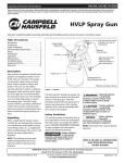
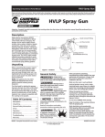
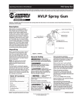
 Operating Instructions and Parts Manual
HV2100, HV2105
Please read and save these instructions. Read carefully before attempting to assemble, install, operate or maintain the product described.
Protect yourself and others by observing all safety information. Failure to comply with instructions could result in personal injury and/or
property damage! Retain instructions for future reference.
HVLP Paint Sprayers
BUILT TO LAST
Thank you for purchasing a Campbell Hausfeld product. If you have any technical
questions about this product, please call 1-800-626-4401.
For Parts and Accessories: 1-800-626-4401
NOTE: If you purchased Model HV2105, please refer to page 8 for additional
instructions on the setup and operation of your product.
REMINDER: Keep your dated proof of purchase for warranty purposes! Attach it to this manual or file it for safekeeping.
© 2002 Campbell Hausfeld/Scott Fetzer
For parts, product & service information
visit www.chpower.com
IN422300AV 11/02
HV2100, HV2105
Operating Instructions and Parts Manual
Table of Contents
Description . . . . . . . . . . . . . . . . . . . . . . . . . . . . . . . . . . . . .
Safety Guidelines . . . . . . . . . . . . . . . . . . . . . . . . . . . . . . . .
General Safety Information . . . . . . . . . . . . . . . . . . . . . . . .
Grounding Instructions . . . . . . . . . . . . . . . . . . . . . . . . .
How Your HVLP System Works . . . . . . . . . . . . . . . . . . . . .
How Your HVLP Spray Gun Works . . . . . . . . . . . . . . . . . .
Pre-Operation . . . . . . . . . . . . . . . . . . . . . . . . . . . . . . . . . . .
Preparing to Use System . . . . . . . . . . . . . . . . . . . . . . . .
Familiarizing Yourself With Spray Gun . . . . . . . . . . . .
Coatings . . . . . . . . . . . . . . . . . . . . . . . . . . . . . . . . . . . . .
Preparing to Spray . . . . . . . . . . . . . . . . . . . . . . . . . . . .
Operation . . . . . . . . . . . . . . . . . . . . . . . . . . . . . . . . . . . . . .
Spray Patterns . . . . . . . . . . . . . . . . . . . . . . . . . . . . . . . .
Using Your Spray Gun . . . . . . . . . . . . . . . . . . . . . . . . . .
Spraying Technique . . . . . . . . . . . . . . . . . . . . . . . . . . . .
Running Multiple Spray Guns with Turbine . . . . . . . .
Using Pressure Pots with Turbine Systems . . . . . . . . . .
Using Optional Accessories with Spray Gun . . . . . . . .
Description
This product is a High Volume Low
Pressure (HVLP) Paint Sprayer, a
durable, self-contained painting system
suited for painting cabinets, furniture,
machinery, equipment, walls, trim, and
many other surfaces. HVLP systems
operate differently than those used with
air compressors because HVLP systems do
not require an air tank to hold
compressed air. HVLP turbines are
portable, can be plugged into standard
outlets and sound similar to shop-vacs.
Safety Guidelines
This manual contains information that
is very important to know and
understand. This information is
provided for SAFETY and to
PREVENT EQUIPMENT PROBLEMS. To
help recognize this information,
observe the following symbols.
Danger indicates
an imminently
hazardous situation
which, if not avoided, will result in
death or serious injury.
!
DANGEr Warning indicates
2
2
2
3
4
4
4
4
4
5
6
6
7
7
7
7
8
8
Additional Instructions for
Model HV2105 . . . . . . . . . . . . . . . . . . . . . . . . . . . . . . . . . . . . . 8
Unpacking . . . . . . . . . . . . . . . . . . . . . . . . . . . . . . . . . . . 8
Attaching Turbine Unit to Cart . . . . . . . . . . . . . . . . . . 8
Converting Spray Gun from Cup Gun to
Production Fluid Feed . . . . . . . . . . . . . . . . . . . . . . . . . . 8
Attaching Air Hose and Fluid Hose . . . . . . . . . . . . . . . 9
Preparing to Spray . . . . . . . . . . . . . . . . . . . . . . . . . . . . 9
Setting Pot Pressure and Priming Spray Gun . . . . . . . 9
Cleaning the System . . . . . . . . . . . . . . . . . . . . . . . . . . 10
Maintenance . . . . . . . . . . . . . . . . . . . . . . . . . . . . . . . . . . . 10
Turbine Maintenace . . . . . . . . . . . . . . . . . . . . . . . . . . 10
Cleaning Spray Gun . . . . . . . . . . . . . . . . . . . . . . . . . . 10
Troubleshooting Chart . . . . . . . . . . . . . . . . . . . . . . . . . . . 12
Turbine Repair Parts . . . . . . . . . . . . . . . . . . . . . . . . . . . . . 13
Parts Diagrams and Parts Lists . . . . . . . . . . . . . . . . . . . . . 14
Warranty . . . . . . . . . . . . . . . . . . . . . . . . . . . . . . . . . . . . . . 20
Caution indicates a
potentially
hazardous situation
which, if not avoided, MAY result in
minor or moderate injury.
!
CAUTION Notice indicates
important
information, that if
not followed, may cause damage to
equipment.
NOTICE
• Paints and solvents containing
HALOGENATED HYDROCARBONS can react
explosively with aluminum. DO NOT USE
HALOGENATED HYDROCARBONS WITH
THIS EQUIPMENT. Consult the paint or
solvent product label or Material Safety
Data Sheets (MSDS) to help determine if
it contains halogenated hydrocarbons.
Unpacking
• Make sure the room is wellventilated.
After unpacking the unit, inspect
carefully for any damage that may
have occurred during transit. Make
sure to tighten fittings, bolts, etc.,
before putting unit into service.
• Avoid all ignition sources, such as static
electricity sparks, open flames, hot
objects, sparks from connecting and
disconnecting power cords, and working
light switches.
Do not operate
! WArNING unit if damaged
during shipping,
handling or use. Damage may result in
bursting and cause injury or property
damage.
General Safety
Information
Read all instructions and
safety precautions before
operating the unit.
! WArNING
•
Risk
of fire or explosion! Solvent
and paint fumes can
explode or ignite, causing severe injury
www.chpower.com
2
• Follow the material and solvent
manufacturers’ safety precautions and
warnings. Do not use liquids with flash
points less than 100 degrees Fahrenheit
(38 degrees Celsius).
• Unit is not intended for spraying
flammable materials other than lacquer.
See Special Note on Lacquers and Other
Oil (Solvent) Based Coatings.
• Do not carry TURBINE while spraying.
MANUAL
! WArNING a potentially
hazardous situation
which, if not avoided, could result in
death or serious injury.
and property damage.
• Keep the turbine at the maximum
distance from the spraying area.
• Static electricity can be produced by
HVLP spraying. Make sure any electrically
conductive object being sprayed is
grounded to prevent static sparking. The
sprayer is grounded through the electric
cord. If an extension cord is necessary, the
cord must be a grounded, 120 volt, three
Operating Instructions and Parts Manual
HV2100, HV2105
HVLP Paint Sprayers
wire type cord.
General Safety
Special note on lacquers and
other oil (solvent) based
coatings
When mixing or thinning:
1. Eliminate potential sources of fire
• Turn off the HVLP sprayer, all other
electrical appliances, spark or flame
sources
• Follow lacquer (or other coating) and
thinner (solvent) manufacturer
directions very carefully
2. Minimize vapors in the spray area.
Eliminate all potential for spilling
lacquer or thinner in the spray area
• Tightly recap all containers
immediately after mixing or thinning
and store away from the spray areas.
• Do not operate the HVLP turbine in
the presence of open containers or
spillage.
• Make sure all vapors have dispersed
prior to turning the HVLP sprayer on.
pressure delivery tube and fittings. The
spray gun does not function when
clogging occurs.
• When not in use, be sure to disconnect
the hose and place the gun on a solid,
level surface or in the turbine gun
storage area to avoid tipping.
Grounding Instructions
This product must be properly
grounded. In the event of an electrical
short circuit, grounding reduces the
risk of electrical shock by providing an
alternate path for the electrical
current.
This product is equipped with a cord
that has a ground wire and an
appropriate ground plug. Plug the unit
into an outlet that is properly installed
Grounded
Outlet
TEST
Grounding Pin
Information
Figure 1 - Grounding
RESET
Grounded Outlet
Box
(Cont.)
! WArNING
• Hazardous vapors: Paints, solvents,
insecticides, and other
materials may be harmful if
inhaled, causing severe
nausea, fainting, or
poisoning.
• Always wear a mask or respirator and
eye protection when painting. Be certain
mask or respirator will provide necessary
protection against inhalation of harmful
vapors.
• NEVER point the spray gun at any part
of the body, or at anyone else.
!
CAUTION
• Tipping the gun may cause the gun to
clog. Dried spray material clogs the
and grounded in
accordance with local codes
and ordinances.
!
DANGEr
of the ground plug can result in the risk of
electrical shock. If repair or replacement
of the plug or cord is necessary, consult an
authorized service provider.
1. For any questions regarding proper
installation of the ground plug,
consult a qualified (licensed or
certified) electrician.
2. Do not modify the plug provided. If
the plug does not fit the outlet,
have the proper outlet installed by
a qualified electrician.
3. This product is for use on a nominal
120-volt circuit and has a grounding
plug that looks like the plug in
Figure 1. Make sure that the
product is connected to an outlet
having the same configuration as
the plug. No adapters should be
used with this product.
4. If an extension cord is required, use
only a three wire extension cord
that has the same configuration as
the unit cord, including the (round)
ground terminal. Make sure that
the extension cord is plugged into a
properly grounded receptacle.
5. When using an extension cord, be
sure it is in good condition and
heavy enough to meet the
specifications in the chart below. If
an extension cord is needed, the
following wire sizes must be used
Improper installation
Extension Cord Requirements
Length of Cord
Gauge
25’ . . . . . . . . . . . . . . . . . . . . . . . . . . . . . . . . . . . . . 16 25-50’ . . . . . . . . . . . . . . . . . . . . . . . . . . . . . . . . . . 14
50-100’ . . . . . . . . . . . . . . . . . . . . . . . . . . . . . . . . . 12
100-150’ . . . . . . . . . . . . . . . . . . . . . . . . . . . . . . . . 10
Table 1 - Appropriate Extension Cord Lengths
www.chpower.com
3
HV2100, HV2105
Operating Instructions and Parts Manual
HVLP Paint Sprayers
(See Table 1).
How Your HVLP
System Works
Your turbine system has three
components: the turbine unit, an air
hose and a spray gun. The turbine unit,
when connected to the correct
electrical power supply and powered
on, provides a continuous source of
clean, warm, dry, High Volume Low
Pressure air. The air hose connects the
turbine unit to the spray gun. Air flows
through the hose to the nozzle of the
specially designed spray gun.
Atomization of the coating is achieved
when the air mixes with the stream of
fluid passing through the tip/nozzle.
This low pressure atomization principle
achieves minimum misting (overspray)
to the spray environment.
The turbine blower has one air hose
outlet on the side of the unit and is
designed to run one spray gun. The
4-stage model has the capability to run
two spray guns at the same time with
an optional “Y” connector. When
using only one spray gun, always be
sure that one outlet is capped.
How Your HVLP
Spray Gun Works
Turbine Spray Guns are bleeder type
spray guns. When the turbine is turned
on, air will constantly flow through the
air cap. This helps makes the
equipment more durable. Air also
flows through the air feed tube in
order to pressurize the cup, and deliver
fluid to the tip/nozzle. When the paint
flow screw is opened and the trigger
pulled back, fluid flows through the
tip/nozzle, mixing with the air flow
delivered from the air cap. The spray
gun projects a fine atomized mist on
your work piece.
Pre-Operation
Preparing to Use Your HVLP
Turbine System
1. Connect the air hose to the turbine.
Pull back the spring loaded quick
disconnect coupler and insert the
male connector on the air hose into
the turbine connector. Release the
ring. Your air hose will be locked
into place. To disconnect, pull back
on the connector to release the air
hose.
!
If you have just CAUTION finished spraying,
the metal coupler at
the turbine end may be hot.
2. Plug the electric cord into a
correctly grounded electrical outlet.
1. Use this position when spraying across from side to side.
2. Use this position when spraying from top to bottom.
3. Use this position for spotting small objects, corners and sharp angles.
Figure 2 - Material flow knob positions and spray patterns
www.chpower.com
4
Operating Instructions and Parts Manual
HV2100, HV2105
HVLP Paint Sprayers
Be sure the electric current is the
correct voltage. If you need to use
an extension cord, be sure it is at
least 12 gauge wire and has a
correctly grounded outlet.
3. Select a safe, well ventilated area
where you will spray your work
piece. Locate your turbine unit
away from the area where you will
be directly spraying. Do not cover
or enclose the turbine. It is
important to draw cool/ambient air
through the unit for optimum
performance. Avoid placing the
turbine in a warm environment or
in direct sunlight.
FAMILIARIZING YOURSELF WITH
YOUR SPRAY GUN
HVLP Spray Gun:
1. Slide the lever to one side, releasing
the cup from the holding pins on
the cup. Reverse the procedure to
install the cup onto the gun body.
Make sure the cup is secure. Be sure
the cup is centered on the gasket
under the top of the cup.
2. Familiarize yourself with the
controls on the spray gun. There
are three main controls: rotating air
cap, material flow knob and air cap
locking ring. Click the rotating air
cap into each position: horizontal,
vertical and 45°. When the air cap is
in the 45° position the pattern is
round. This is useful for spraying
small, narrow pieces of work. Paint
flow will increase when using the
diagonal position. It is usually
necessary to reduce the paint flow
by adjusting the flow knob. (See
Figure 2)
3. Turn the material flow knob
counterclockwise to open or release
more fluid, clockwise to reduce or
close material flow.
Pre-Operation
COATINGS
to adjust the coating properties such as
speeding up or slowing down the
drying time, adding catalysts to
strengthen the molecular bond or
adding flattening agents to lower the
sheen. Manufacturers will often give
some guidelines on how to thin their
product for spray application.
Coating Properties: Coatings are a
blend of resins and additives to create
a product that will provide a protective
and beautifying surface to your work
piece. Different resins have different
properties. It is important to use the
correct coating to achieve a desired
There are many different types of spray
equipment in use. Coating
manufacturers cannot address all of
them. Make sure you know about your spray equipment. Make sure to
use the correct fluid viscosity to
produce the best possible results.
Turbine Performance
Your Choice of Coatings and
Viscosity: Extremely thin, watery or
light bodied fluids such as inks, aniline
dyes and oil stains can generally be
used straight from the can. Most water
based finishing products are also
formulated to be used straight from
the can without thinning with a 3
stage or larger turbine. Most other
coating products will need to be
thinned anywhere from 10% to 50%
depending on the available air
pressure of the turbine model and the
properties of the coating selected (see
(Cont.)
4. Loosen the air cap locking ring one
or two turns. This will feather the
top and bottom of the fan pattern
and slightly reduce the fan pattern
size.
Turbine Size . . . . . . . . . . . . . . . . 4 stage
Unrestricted Pressure . . . . . . . . . 7.0 psi
Coating Types
Light-Heavy
Viscosity Materials
Table 2
result. Manufacturers of coatings can
control the resin solids content,
production viscosity, sheen, color, flowout enhancement and other
properties. Some products offer ways
Nozzle, Needle, and Air Caps
Tip/Needle Size Application
.75 mm (.0295)
HV104520SV
1.0 mm (.039)
HV104521SV
1.5 mm (.059)
HV104522SV
2.0 mm (.079)
A.5220-2
2.5 mm (.098)
A.5221
Air Cap
Inks, dyes, stains, extremely thin viscosity
HV104505AV
fluids, water based finishes
All purpose, thin lacquers, thin enamels,
HV104505AV
water based finishes, automotive, marine,
airplane finish
Catalyzed lacquers, conversion varnish,
HV104505AV,
primers, automotive, marine, airplane, finish
A.5297
varnish, high viscosity industrial coatings,
urethanes, enamel
Thinned latex paint, multi-spec, heavy
A.5297
primers, butyrate, nitrate dope, high visosity
industrial coatings
Thinned latex paint, multi-spec, solvent
A.5297
adhesives, wax based paint strippers
Table 3 - Needle, Nozzle, and Air Cap Combinations
www.chpower.com
5
Operating Instructions and Parts Manual
HV2100, HV2105
HVLP Paint Sprayers
Table 4).
HVLP Turbine Properties: Each
turbine unit offers the finisher a
maximum operating pressure. This
pressure is determined by the size and
output of the unit you have selected.
The maximum available pressure will
have a direct bearing upon the
viscosity of the fluid that you choose to
spray. Atomizing pressure and fluid
viscosity directly relate to the efficiency
of the equipment operation and the
quality of the results that you will
achieve.
The available air volume and pressure
at the air cap will meet the delivery of
fluid coming out of the nozzle to
create a fine mist called atomization.
This mist travels directly to your work
piece where it blends together to form
a connected wet film. Achieving a
smooth, level surface will depend on
the proper relationship between
available atomizing pressure, the
viscosity of the coating being applied
and the properties of the coating.
Using Latex Paint: Although your
turbine spray system is best suited to
spray Class A Finish coatings such as
lacquers, enamels, urethanes,
varnishes, waterbornes etc., you can
spray latex house paint if you follow a
few simple rules:
1. It is necessary to thin some latex
paints. This will vary from as little
as 5% to no more than 20%. This
will depend on the model turbine
you are using and the quality of the
paint used.
2. It is necessary to use a larger nozzle
and needle set in the spray gun (2.0
mm or 2.5 mm).
3. It is recommended that a latex
conditioner, Floetrol, be added to
aid flow-out. If unable to find this
product, locate one that is labeled
“latex enamel” or “HVLP
compatible.” These products are
available at local paint stores.
Pre-Operation
(Cont.)
PREPARING TO SPRAY
After some practice, you should be
ready to spray your coating of choice
on your work piece. (See the
Viscosity
Type of Coating
Amount to Thin/Reduce (Typical)
Lacquers
25-50%
Sanding Sealer
20-30%
Enamels
Stains
20-40%
Use from can
Acrylic Enamel
50-60%
Catalyzed Polyurethane
10-30%
Polyurethanes, Varnishes
20-30%
Waterborne Coatings
0-10%
Latex Paint, Emulsion Paint
10-40%
NOTE: The amount of thinning needed will depend on the model turbine used,
flow out properties of the coating, and the desired appearance of the finished
work piece. It is best to test spraying results prior to thinning.
Table 4 - Types of Coatings, Recommended Amount of Thinning
www.chpower.com
6
Operation section for more
information on spray patterns, spray
gun use, and other usage procedures).
Good quality results with your HVLP
system are a combination of:
- Careful preparation of your
project
- A proper spraying environment
- A basic knowledge of the coatings
you will be using and how these
coatings work with your spray
equipment
- Close adherence to safety
precautions
Operation
SPRAY PATTERNS
Your spray gun offers you many
options. You can adjust (click) the air
cap to three positions. One will
produce a horizontal pattern for
spraying across, another will produce a
vertical pattern for spraying up and
down, and the third will produce a
round pattern to spray small or narrow
pieces. (See Figure 2.)
USING YOUR SPRAY GUN
Your spray gun is certified High
Volume Low Pressure. This means your
spray gun only uses from 3 psi to 10 psi
(depending on your turbine unit) of air
pressure measured at the air cap. All
passages and air ports are much larger
than on a conventional spray gun. If
one of these air passages becomes
blocked, or buildup of material starts
to occur, your spray pattern will
become distorted. Therefore, always
keep your spray gun clean.
Your spray gun comes fitted with a
1mm tip/nozzle and needle inscribed
with the number “2”. This will cover
about 85% of all the materials/coatings
that you will spray. Using this size tip/
nozzle and needle, you can achieve a
1/4" line up to a 10" fan pattern just
by rotating the air cap to the desired
Operating Instructions and Parts Manual
HV2100, HV2105
HVLP Paint Sprayers
fan type (see Spray Gun Diagrams),
opening the material flow knob
counterclockwise and moving the spray
gun closer or further away from your
work piece. A little practice will enable
you to master this technique.
Practice: Practice using your spray
gun by following these steps:
1. Remove the cup from your spray
gun. Fill it halfway with some
water.
2. Attach the cup to the body of the
spray gun.
3. Attach the spray gun to the air
hose.
4. Turn the turbine unit on.
5. You will notice air is now flowing
through the air cap. This is normal
and correct.
6. Position the air cap in the
horizontal position (see Figure 2)
and turn the material flow knob
counter clockwise approximately 1
to 1-1/2 turns.
7. Point the spray gun away from
yourself (and anyone else) and pull
the trigger all the way back. You
should see a “V” shaped mist (or
triangle) called a fan pattern.
clockwise (closing). Move the spray
gun 1-2” closer to the surface.
Operation
(Cont.)
13.Pull the trigger. Notice the pattern
has become smaller. (You can
continue reducing the material
flow and move the spray gun even
closer to the surface and the
pattern will keep getting smaller).
14.Rotate the air cap to a diagonal
position (See Figure 2).
15.Every so often, turn the material
flow knob to a different position.
Also, change the distance of the
spray gun from work surface. Notice
how doing this changes pattern size.
There is one additional control to
know. If you loosen the air cap locking
ring, approximately 1-2 turns, you can
control the fan pattern size and trim or
feather the edge of the fan pattern
itself. This should be considered a
secondary control, the primary fan
pattern size being adjusted between
8. Now, with the trigger depressed,
slowly begin to turn the material
flow knob clockwise (closing).
Notice that the fan pattern is
beginning to get smaller.
! WArNING
Even when the turbine is turned off,
pressure will remain in the spray cup.
When trigger is pulled back, a stream
of fluid will flow. To prevent accidents,
turn material flow knob clockwise until
it is completely closed, locking trigger
in closed position.
Note: It is not necessary to empty and
clean your spray gun when you pause
between applications. Be sure,
however, to clean your spray gun
thoroughly at the end of your work
session.
Clean spray gun thoroughly at end
of work session. Do
not allow coating to dry in spray gun
overnight or at any time when not in
use.
NOTICE
Extra caution should be taken when
spraying coatings that have a catalyst
or hardener added since many of these
coatings have short pot life. These
coatings can harden in your spray gun
quickly, making cleaning difficult or
impossible. Read manufacturer’s
coating instructions to help determine
how quickly a particular coating will
harden in your spray gun.
SPRAYING TECHNIQUE
Practice is the key element in achieving
a proper spray technique. Never try to
rush the spray finishing process. Learn
the properties of the coating you will
be spraying. Build up layers of material
(3-4 applications, or more if needed).
Sand between coats, if needed, and
allow proper drying time between
applications.
9. Turn the material flow knob
counterclockwise and notice the
pattern get larger.
10.Take a large piece of cardboard and
direct the pattern at the surface.
Turn the material flow knob 2 full
turns and hold the spray gun
approximately 6" from the surface.
Remember to keep the distance of the
spray gun the same when moving
across your work (called a “pass”). Do
not rotate or turn your wrist from side
11.Pull the trigger. Observe the outline
and size of the pattern.
12.Turn the material flow knob
fluid flow and distance of the spray
gun from the work piece.
Figure 3 - Proper Spray Technique
www.chpower.com
7
HV2100, HV2105
Operating Instructions and Parts Manual
HVLP Paint Sprayers
to side (See Figure 3). Move the spray
gun across your work from end to end.
Be sure to maintain the same speed of
movement. This will ensure an even
application of coating. Always release
the trigger at the end of a pass.
Continue spraying in the opposite
direction overlapping your previous
coat by 1/3 to 1/2. When finished, you
should have an even wet coat on your
work. If you have dry spots, you have
overlapped too widely.
If you have heavy or wet spots, you
have overlapped too much. When
spraying a large or pre-assembled
piece, start at the top and work down.
Try to spray the hard-to-reach surfaces
first. Keep in mind that a light, wet
film will generally produce better
results than a heavy, wet coat. When
spraying a vertical surface, apply a
thin“tack” coat first, followed by a
normal light wet coat. This technique
will help prevent “runs” and “sags.”
IMPORTANT: If the “Y” connector is
installed and only one spray gun
operated, the 2nd outlet must be
capped or closed so that performance
to the single spray gun will not be
affected.
Operation
(Cont.)
USING PRESSURE POTS WITH
TURBINE SYSTEMS (HV2105)
When using a remote cup or pressure
pot, it is necessary to introduce
compressed air in order to pressurize
the remote pot and move the fluid
from the pot to the tip/nozzle of the
spray gun. In general, 5 pounds of
pressure is sufficient for most average
viscosity fluids in order to deliver the
proper flow of fluid to the tip. Higher
pressure would only be necessary for a
heavier viscosity fluid.
A good test to determine the correct
fluid delivery is as follows:
When using your Spray Gun you
control five variables.
1. Pressurize the pot. DO NOT turn on
the turbine.
1. Fluid flow
2. Pull spray gun trigger until a stream
of fluid flows from the tip/nozzle.
2. Distance of the spray gun from your
work. (4"–8" is average. Closer if
necessary.)
3. Pattern Direction (vertical fan,
horizontal fan and round)
4. Speed of application
5. Fan pattern control (adjust air cap
ring)
3. Adjust the pressure until the fluid
drops off or bends at approximately
2-1/2 inches (6.35 cm). Pot pressure
should be correct at this point.
! WArNING
RUNNING MULTIPLE SPRAY GUNS
WITH A TURBINE
Always depressurize the remote pot
using the safety valve when the
equipment will be idle for a while. This
will prevent excess fluid from
remaining in the fluid hose, and
prevent a possible accident should the
trigger be pulled and paint streams
from the spray gun.
It is possible to run the 4-stage turbine
system with two spray guns at the
same time by installing “Y” Connector
to the turbine outlet port.
Always ensure that the remote cup is
tightly sealed, and all gaskets are in
good shape, to prevent air and fluid
leaks.
NOTE: Items 1, 2, and 4 directly relate
to each other.
www.chpower.com
8
Be sure to flush and clean fluid hose at
the end of a work session.
For smaller jobs, insert a one gallon can
inside the 2.5 gallon pressure pot. This
will keep the inside of the pot clean.
USING OPTIONAL ACCESSORIES
WITH SPRAY GUN
Option 1: In parts diagram on page
14, locate Item No. 13. Most turbine
spray guns are fitted with this blanking
cap. You can remove the cap and install
Item Nos. 14A and 14B. This gives you
the option to attach your air hose onto
this port instead of into the handle. To
install, unscrew blanking cap. Screw in
Item No. 14A and 14B. To use this port,
unscrew the male hose coupler and
screw onto Item No. 14A. Take the
small blanking cap (Item No. 14B) and
screw it onto the threads at the
bottom of the handle. Reverse these
two fittings to use the air hose coupled
to the handle.
Option 2: This will allow you to
control the air flow and create
textured or splatter paint effects. To
install, remove blanking plug (Item No.
13) or Item Nos. 14A and 14B. Screw
Item No. 13A into the spray gun. After
installing the air control/texturing
device, turn the adjusting screw as far
as you can counter clockwise (open).
Always use in the full open position
unless it is necessary to reduce the flow
of air, or to create a textured or
splatter effect.
Additional
Instructions for Model
HV2105
UNPACKING
Remove contents of shipping box and
lay out all of the pieces. You will find
the cart base, handle, 2.643 gallon
(10L) pressure pot (with regulator,
HV2100, HV2105
Operating Instructions and Parts Manual
HVLP Paint Sprayers
gauge, safety valve and connectors
attached), 3/8” black lined fluid hose,
bag of nuts and bolts for assembly, and
instructions.
NOTE: Do not place pressure pot onto
the cart or insert handle into cart base
until the turbine unit is firmly bolted
and secured to the cart. Using the cart
without the turbine installed can result
in the cart tipping over.
AttachING Turbine Unit to Cart
1. Set the turbine unit on the cart
base plate with the turbine air
hose quick disconnect coupler
facing out.
2. Line up the four holes on the
turbine base plate with the four
holes on the cart base plate.
3. Secure turbine unit to cart base
plate with the four hex bolts,
washers and hex nuts (supplied).
Insert bolt through the holes, place
washer over the bolt on the
underside, screw hex nut onto bolt
and tighten. Be sure that hex nut is
tight enough so as not to vibrate
loose.
4. Insert the chrome handle into the
frame tube. Be sure to push handle
all the way down so that the spring
loaded buttons lock into place,
securing the handle firmly.
5. Plug turbine unit into outlet on
side of the Cart.
4. Place the 2.643 gallon (10L)
pressure pot onto the pressure pot
deck. Align the fluid outlet toward
the front of the cart. This will
position air inlet toward the back
of the cart.
Note: Pressure pot support rings can
be adjusted for use with different size
pressure pots.
Convert Spray Gun from Cup
Gun to Production Fluid Feed
1. Remove cup assembly.
a. Disconnect the upper section of
the air feed tube from the non-
Additional
Instructions for
Model HV2105 (Cont.)
return valve, leaving the valve
attached to the lower section of
the tube. This will provide safe
storage while using the spray gun
without the cup in a production
mode.
b. With a wrench, loosen the center
bolt and remove the cup assembly.
Set aside.
c. Remove air feed connector and
upper section of air feed tube
with small wrench.
d. Install the blanking screw
provided (10/32”) to close the hole
where you removed the air feed
connector. Store the air feed
connector with tube attached in
the cup assembly for future use.
Attaching Air Hose and Fluid
Hose
1. Attach turbine air hose to handle
of spray gun with quick disconnect
coupler.
2. Insert the male coupler on the
other end of the air hose into the
quick disconnect coupler on the
turbine unit. 3.
On spray
gun, put a strip of PTFE tape
around the threads on the fluid
connector.
4. Screw one end of the black fluid
hose onto fluid connector. Secure
and tighten.
5. Locate paint outlet on lid of the
2.643 gallon (10L) pressure pot
(marked on the pot). Put a strip of
PTFE tape around the threads of
the Fluid Connector.
6. Take the other end of the black
fluid hose and attach it to the
paint outlet (marked on the pot).
Secure and tighten.
7. Locate the compressor under the
Pressure Pot Deck. Take the air
hose from the compressor and
connect the female quick
disconnect to the male connector
(marked air inlet).
8. Your cart system is now set up for
production spraying.
Preparing to Spray
Note: Never open the pressure pot
without turning off the air compressor
and releasing the air pressure in the
pot with the air pressure release valve.
(Open valve until all pressure is
released. Pressure gauge will read “0
psi” when there is no more pressure in
the pot).
1. Prepare your paint or coating for
spraying. Adjust viscosity as
recommended. See page 6 for
viscosity guidelines.
2. Carefully loosen the four wing nuts
to remove the pot lid. Open the
pressure pot. (Note: You may have
to disconnect the air hose from the
compressor when opening the lid.
Be sure to reconnect air hose when
the lid is closed again). You can
either pour your coating into the
pot, or you can insert a smaller
container inside the pot, making
sure that the material pick-up tube
is inserted into the coating. Place
the lid back on top of the pressure
pot, making sure that it is properly
seated. Bring each wing nut back
into place and secure the lid firmly.
3. Secure each wing nut into place
www.chpower.com
9
HV2100, HV2105
Operating Instructions and Parts Manual
HVLP Paint Sprayers
using a cross pattern, rotating an
even amount of pressure on each
one until each is tight and secure.
preset at the factory and should not
be readjusted.
4. Plug the power cord into a proper
grounded receptacle outlet.
Additional
Instructions for Model
HV2105 (3F485) (Cont.)
If you are using an extension cord, it is
imperative to use at
least a 12 gauge cord to avoid damage
to electrical components.
NOTICE
Setting Pot Pressure and
Priming Spray Gun
5. Turn on the mini-compressor unit.
Locate the on/off switch, which is
mounted on top of the silver box
on the compressor located at the
back of the cart. Move the switch to
the “ON” position. You should hear
the compressor activate.
6. Look at the pressure gauge located
on top of the pressure pot lid. You
will notice the gauge begin to rise.
Attached to the pressure gauge is
the pressure regulator. The pressure
gauge will tell you how much
pressure is in the pressure pot.
Generally you will only need about
5 psi for most light to medium
viscosity fluids. Increasing pressure
should only be necessary for high
viscosity fluids.
7. If the pressure rises above the
desired maximum, you can release
pressure in the pot with the air
release valve and control the
maximum amount of pressure with
the pressure regulator.
8. To decrease pressure, rotate the
knob on the pressure regulator
counterclockwise. To increase
pressure rotate the knob clockwise.
Stop when the desired pressure is
achieved.
9. Your compressor is set to shut off
when the desired pressure is
reached and back on when the
pressure drops down. This has been
Note: The following action should be
done without the turbine running.
10.When your desired pot pressure has
been set, pull the spray gun trigger
back. The first time you are using
the pressure pot each day, or after
the pressure pot has been
depressurized, it will take about a
minute for the material to flow
through the fluid hose to the spray
gun (priming the spray gun).
11.Hold the spray gun safely away
from you. When the material
reaches the tip of the spray gun, a
stream of fluid will flow out.
12.Watch the fluid stream. It should
extend out 2-1/2” (6.35 cm) before
the stream begins to bend. If it
extends out more than this, then
you have too much pressure. If it is
too little, then you need more
pressure. Adjust accordingly.
released. Pressure gauge will read “0
psi” when there is no more pressure in
the pot).
Cleaning the System
1. When you are finished spraying for
the day, it is wise to clean your
spray gun, the pressure pot and the
fluid line. While it is possible to
leave fluid in the pressure pot
between uses, be sure that all
materials are compatible with the
components of the pressure pot to
avoid fluid contamination. Never
leave catalyzed or epoxy materials
in the pot beyond suggested pot
life of the fluid product to avoid set
up and hardening of the coating
and damage to the pot, its
components, fluid lines and the
spray gun.
2. Release all air pressure in the pot.
Locate the air release valve and
turn counterclockwise.
3. You will hear a “hissing” sound.
The pressure in the pot is now
releasing. You will also notice that
pressure gauge will lower to “0
psi”. Once there is no more pressure
in the pot, it is safe to open.
13.Once this is adjusted, locate the
black ring on the pressure regulator
and screw it back into the pressure
regulator knob. This will lock the
regulator settings in place.
4. Follow normal cleaning procedures
of the spray gun as outlined in the
Maintenance section and in the
information supplied with the spray
gun.
14.Turn on the turbine system. You
should now be able to spray
continuous volume from the
pressure pot.
5. Clean pressure pot and fluid lines
with appropriate cleaning materials
for the product being sprayed. Use
caution and follow all safety
guidelines specirfied by the product
manufacturer.
Note: Never open the pressure pot
without turning off the air compressor
and releasing the air pressure in the
pot with the air pressure release valve.
(Open valve until all pressure is
6.. Spray cleaning fluid from the
pressure pot through the fluid line
and the spray gun until you are
satisfied that all paint or coating
material has been flushed through
the system.
Store equipment for future application.
www.chpower.com
10
Operating Instructions and Parts Manual
HV2100, HV2105
HVLP Paint Sprayers
Maintenance
TURBINE MAINTENANCE
The turbine unit needs very little
maintenance. The motor has sealed
bearings that are pre-lubricated. No
service is necessary. Periodically, the
turbine air filters and pre-filters should
be examined. Clean filters are critical
to good performance and equipment
longevity. Your turbine has 2
replaceable filters (see Turbine Repair
Parts on page 13).
- Remove the two hex-head securing
nuts in order to remove the filters
for cleaning or replacement.
- Periodically wash and blow excess
dust and dirt with water and an air
compressor. Dirty filters will reduce
the air being drawn through the
motor. This will cause the unit to run
unusually hot, and it will lower spray
performance and reduce the life of
the motor.
- Clean and/or replace filters and prefilters when you suspect they can no
longer be cleaned.
CLEANING YOUR SPRAY GUN
After spraying, clean your spray gun to
prevent buildup and hardening of
coating inside. Proper cleaning will
help prevent equipment damage and
will increase equipment life.
1.Empty any unused paint from the
paint cup. Wash out any residue with
a cleaner compatible with the
coating, or water if using a water
based material.
2.Fill the cup part way with cleaner.
Spray through the gun to flush out
the material passages.
3.Remove the air cap and clean. Make
sure that the air holes in the horns
of the air cap are clean.
4.Using a brush and solvent, remove
any paint deposits on the outer
surface of the tip/nozzle. If it is
Maintenance
(Cont.)
necessary to remove the tip/nozzle
and needle for cleaning, the
following procedure should be used:
a.Unscrew the material flow knob.
Remove the needle spring, and
then withdraw the needle.
b.Remove the tip.
c. Clean both tip and needle using
cleaner or water and a brush.
d.Reassemble all parts, making sure
that all washers and gaskets are
replaced correctly.
e.Oil the needle spring and put a
spot of oil on the gland seal to
prevent the needle from sticking.
To adjust the gland nut, tighten
until needle sticks, and then
slacken off by about 1/8 turn.
f. Check the cup top gasket and
replace if damaged. Always seat
the cup top gasket flat in the cup
groove. Failure to do this will
allow the cup to drip and impair
the spray pattern due to loss of
pressure.
g.Lubricate all threads to ensure
smooth operation.
Blockages and or leaks may occur if the
gun is left on its side or turned upside
down. Always hang the gun by the
hook when not in use.
www.chpower.com
11
Operating Instructions and Parts Manual
HV2100, HV2105
HVLP Paint Sprayers
Troubleshooting Chart
Symptom
Possible Cause(s)
Corrective Action
1. Cup not pressurizing due to
loose fittings
2. Cup not pressurizing due to
loose cup connection
3. Cup top gasket damaged
4. Blockage in “C” shaped tube
underneath cup top lid
1. Check air feed tube/one way air valve and air feed
connector.
1. Too much distance from spray
gun to work piece
2. Too much spray material
coming out
3. Too much air power behind
pressure stream
4. Tip/needle assembly too large
1. Move spray gun closer to work piece.
Coating on surface of
work piece is not flat and
level after drying (orange
peel effect)
Coating not strained/thinned
properly
Thin coating more.
When spray gun is
connected to turbine and
turbine is on, air
continually flows through
air cap even if trigger is
not pulled
N/A. This is normal and expected.
“Bleeder” type guns are set up
this way to help increase the life
of the turbine motor.
No paint comes out when
trigger is pulled
Excessive overspray
2. Make sure cup is screwed on or clamped on tightly.
3. Check for damage and replace if necessary.
4. Look under cup top lid. Locate “C” shaped tube. Remove
blockage from it.
www.chpower.com
12
2. Decrease the amount of spray material flowing through
spray gun.
3. Reduce air power (use optional air control/texturing
device).
4. Use a smaller tip/needle assembly instead of the current
one you are using.
Operating Instructions and Parts Manual
HV2100, HV2105
For Replacement Parts, Call 1-800-626-4401
Please provide following information:
-Model number
-Serial number (if any)
-Part descriptions and number as shown in parts list
Address parts correspondence to:
Campbell Hausfeld
100 Production Drive
Harrison, OH 45030 U.S.A.
Turbine Repair Parts
2-1/2 Gallon (10L) Cart
and Fluid Feed System
Part No. HV210510AV
Filter Assembly
Part No. CH4098
25’ Air Hose
Part No. HV0126
5’ Whip Hose
Part No. HV0125
Parts Not Pictured:
Female Quick Connect for Air Hose
Part No. HV002200AV
Male Quick Connect for Turbine
Part No. PM068020AV
www.chpower.com
13
HV2100, HV2105
Operating Instructions and Parts Manual
Spray Gun with Quick Release Cup
www.chpower.com
14
HV2100, HV2105
Operating Instructions and Parts Manual
For Replacement Parts, Call 1-800-626-4401
Please provide following information:
-Model number
-Serial number (if any)
-Part descriptions and number as shown in parts list
Address parts correspondence to:
Campbell Hausfeld
100 Production Drive
Harrison, OH 45030 U.S.A.
Parts List for Spray Gun with Quick Release Cup
Ref. No.
Description
Part NumberQty.
1
2
3
4
5
6 ▲
7
8
9
10
11
12
13
13a
14a
14b
15
16
17
18
19
20
21
22
23
24
25
26
27
28
29
30
31
32
33
34
35
Air cap ring
A.5200
Air cap #2
HV104505AV
Air cap #3
A.5297
Air distributor plate (stainless)
HV104511AV
Air distributor spring (stainless)
HV104512AV
Not applicable
Fluid nozzle/jet (stainless) 0.75mm
HV104520SV
Fluid nozzle/jet (stainless) 1.00mm
HV104521SV
Fluid nozzle/jet (stainless) 1.50mm
HV104522SV
Fluid nozzle/jet (stainless) 2.00mm
A.5220-2
Fluid nozzle/jet (stainless) 2.50mm
A.5221
Fluid nozzle gasket
HV104524AV
Air feed connector
A.5211
Not applicable
Trigger bushing (comes with Item No. 11)
HV104521SV
Trigger pivot screw (stainless) (comes with Item No. 10)
HV104521SV
Trigger screw washer
HV104508AV
Air blanking plug
A.5202
Air control texturing valve
A.5257
Upper port insert
HV103901AV
Air blanking plug
HV104001AV
Needle (stainless) 0.75mm
▲
Needle (stainless) 1.00mm
▲
Needle (stainless) 1.50mm
▲
Needle (stainless) 2.00mm
▲
Needle (stainless) 2.50mm
▲
Needle spring (stainless)
HV104513AV
Adjuster insert
HV104503AV
Material flow knob
HV104502AV
Gun casting (handle)
A.5225
Handle tube
A.5226L
Air hose quick release coupler (male)
A.5227
Packing
HV104514AV
Packing nut
HV104515AV
Trigger
HV104507AV
Air feed tube and non return valve
A.5232
Center bolt/pickup tube
A.5274
Yoke
A.5271
Lever
A.5278
Cup top casting
A.5270
90 degree miniature brass block
A.5266
Cup top lock nut
A.5272
Cup top gasket (white poly)
A.5280
Quick release cup
DH077900AV
Quick release cup (PTFE coated)
A.5277
Not applicable
3/8” Fluid connector
A.5254
1
1
1
1
1
1
1
1
1
1
1
1
1
1
1
1
1
1
1
1
1
1
1
1
1
1
1
1
1
1
1
1
1
1
1
1
1
1
1
▲ All fluid/nozzle jets (Item No. 6) include the corresponding needle of the same size (Item No. 15).
www.chpower.com
15
HV2100, HV2105
Operating Instructions and Parts Manual
Cart Assembly
For Model HV2105 only
www.chpower.com
16
HV2100, HV2105
Operating Instructions and Parts Manual
Parts List for Cart Assembly, For Model No. HV2105 Only
Ref. No.
Description
Part NumberQty.
Cart base plate paint blue
Cart axle (zinc plated)
Wheel spacer (6061 alu.)
10” x 1-3/4” wheel
1/2” Axle cap
Frame tube (chrome)
Rubber tip for frame tube
Handle button
1/4” x 20 x 1-1/4” Hex bolt plated .5.
1/4” SAE F/W plated washer
1/4” x 20 Hex nuts plated
110V Mini compressor nut
Pressure regulator
1/8” male NPT x 1/4” male hose barb 90o
Air hose clip (stainless steel)
1/4” Air hose, per foot
1/4” x 1/4” Female swivel barb
Quick connect female with 1/4” male thread
1/4” x 20 x 1/2” Hex bolt plated .5.
Pressure pot deck
6-32 x 1/2” Phill pan M/S plated
6-32 Hex M/S nuts plated
Cable clamps, black
Outlet box (plastic)
Outlet 15 Amp-125 volt
Flexible cord protector
8’ Power cord
Large ring terminal
Support ring for pressure pot
2.5 gallon pressure pot
Handle (chrome)
Handle grip
A.4554
A.4555
A.4556
A.4558
A.4374
A.4551
A.4559
A.4560
A.4364
A.4300
A.4308
A.4198
A.4998
A.4503
A.4033
A.2116
A.2119
A.4026
A.4320
A.4553
A.4318
A.4307
A.4051
A.4557
A.4197
A.4053
A.4028
A.4178
A.4552
A.4113
A.4006
A.4042
1
2
3
4
5
6
7
8
9
10
11
12
13
14
15
16
17
18
19
20
21
22
23
24
25
26
27
28 29
30
31
32
1
1
2
2
2
2
2
2
4
20
20
1
1
1
2
3
1
1
16
1
4
2
2
1
1
1
1
3
2
1
1
2
www.chpower.com
17
HV2100, HV2105
Operating Instructions and Parts Manual
Fluid Tank Assembly
For Model HV2105 only
www.chpower.com
18
HV2100, HV2105
Operating Instructions and Parts Manual
Parts List for Fluid Tank Assembly, For Model No. HV2105 Only
Ref. No.
Description
Part NumberQty.
Fluid tank
Lid assembly
Handle
Gasket
Material pickup tube
Material filter housing
Filter base
Material filter element
Snap ring
T-bolt
Washer
Wing nut
Pressure regulator
Pressure gauge
On/off valve
3-Way block
1/4” x 1/4” Adapter
3-Way block
Adapter
Nut
Steel ball
Needle rod
Spring
Safety valve housing
Adapter
O-ring
Release valve
Material outlet adapter
Adapter
Cotter pin
C-Snap ring
Wrench
A.4901
A.4902
A.4903
A.4904
A.4905
A.4906
A.4907
A.4908
A.4909
A.4910
A.4911
A.4912
A.4913
A.4914
A.4915
A.4916
A.4917
A.4918
A.4919
A.4920
A.4921
A.4922
A.4923
A.4924
A.4925
A.4926
A.4927
A.4928
A.4929
A.4930
A.4931
A.4932
1
2
3
4
5
6
7
8
9
10
11
12
13
14
15
16
17
18
19
20
21
22
23
24
25
26
27
28
29
30
31
32
1
1
1
1
1
1
1
1
1
4
4
4
1
1
1
1
3
1
1
1
1
1
1
1
1
1
1
1
1
4
8
1
www.chpower.com
19
HV2100, HV2105
Operating Instructions and Parts Manual
Limited Warranty
1.Duration: From the date of purchase by the original purchaser as follows: Standard Duty Paint Application Systems and all
Paint Application Accessories - 1 year, Serious Duty Paint Application Systems - 3 years, Extreme Duty Paint Application Systems
- 5 years.
2.Who Gives This Warranty (Warrantor): Campbell Hausfeld/A Scott Fetzer Company, 100 Production Drive, Harrison,
Ohio, 45030, Telephone: 1-800-626-4401.
3.Who Receives This Warranty (Purchaser): The original purchaser (other than for purposes of resale or rental) of the
Campbell Hausfeld Product.
4.What Products Are Covered By This Warranty: All non-compressor driven paint application systems, HVLP spraying
systems, and paint application accessories supplied or manufactured by the Warrantor.
5.What Is Covered Under This Warranty: Defects in material and workmanship which occur within the duration of the
warranty period. Warrantor will also cover normal wear items for a period of thirty days from the date of original purchase
against defects in material and workmanship. These wear items are: HVLP-filters, motor brushes, gun packing, gun canister
seal, gun check valve and gun air flow ring; Airless-inlet valve, outlet valve, gun valve, filters, tips, all seals and o-rings.
6. What Is Not Covered Under This Warranty:
A. Implied warranties, including those of merchantability and FITNESS FOR A PARTICULAR PURPOSE ARE LIMITED FROM THE
DATE OF ORIGINAL PURCHASE AS STATED IN THE DURATION. If product is used for rental purposes, the warranty will
apply for ninety (90) days from the date of original purchase. Some states do not allow limitation on how long an implied
warranty lasts, so the above limitations may not apply to you.
B. ANY INCIDENTAL, INDIRECT, OR CONSEQUENTIAL LOSS, DAMAGE , OR EXPENSE THAT MAY RESULT FROM ANY DEFECT,
FAILURE, OR MALFUNCTION OF THE CAMPBELL HAUSFELD PRODUCT. Some states do not allow the exclusion or
limitation of incidental or consequential damages, so the above limitation or exclusion may not apply to you.
C. Any failure that results from an accident, purchaser’s abuse, neglect or failure to operate products in accordance with
instructions provided in the owner’s manual(s) supplied with product. Accident, purchaser’s abuse, neglect or failure to
operate products in accordance with instructions shall also include the removal or alteration of any safety devices. If such
safety devices are removed or altered, this warranty is void.
D. Normal adjustments which are explained in the owner’s manual(s) provided with the product.
E. Items or services that are normally required to maintain the product: HVLP-filters, motor brushes, gun packing, gun
canister seal, gun check valve and gun air flow ring; Airless-inlet valve, outlet valve, gun valve, filters, tips, all seals and
o-rings., or any other expendable part not specifically listed, will only be covered for thirty days from date of original
purchase.
7. Responsibilities of Warrantor Under This Warranty: Repair or replace, at Warrantor’s option, products or components
which are defective, have malfunctioned and/or failed to conform within duration of the warranty period.
8. Responsibilities of Purchaser Under This Warranty:
A. Provide dated proof of purchase and maintenance records.
B. Deliver or ship the Campbell Hausfeld product or component to the nearest Campbell Hausfeld Authorized Service Center.
Freight costs, if any, must be borne by the purchaser.
C. Use reasonable care in the operation and maintenance of the products as described in the owner’s manual(s).
9. When Warrantor Will Perform Repair or Replacement Under This Warranty: Repair or replacement will be
scheduled and serviced according to the normal work flow at the servicing location, and depending on the availability of
replacement parts.
This Limited Warranty applies in the U.S., Canada and Mexico only and gives you specific legal rights. You may also have other
rights which vary from state to state, or country to country.
www.chpower.com
20