1
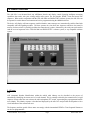
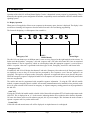
ARi-195e
ANI and Status Desk Top Console
CES WIRELESS TECHNOLOGIES CORP.
925-122 South Semoran Blvd.,
Winter Park, FL 32792
Tel: (407) 679-9440
Fax: (407) 679-8110
e-mail: [email protected]
[email protected]
MAN78 Version
Firmware Version 1.2
A CES PUBLICATION © 1998
Printed in USA
Table of Contents
1.0 INTRODUCTION........................................................................................................................................................................... 4
2.0 PRODUCT OVERVIEW............................................................................................................................................................... 5
2.1 TERMS ........................................................................................................................................................................................... 5
2.2 SIGNALING FORMAT...................................................................................................................................................................... 7
2.3 FRONT PANEL STATUS KEYS ........................................................................................................................................................ 7
2.4 DISPLAY ........................................................................................................................................................................................ 7
2.5 ADDITIONAL FEATURES ................................................................................................................................................................ 7
2.6 PROGRAMMING & INSTALLATION ................................................................................................................................................ 8
3.0 OPERATION................................................................................................................................................................................... 9
3.1 Display Operation................................................................................................................................................................... 9
Audio Alerts ................................................................................................................................................................................. 10
Alert Relay.................................................................................................................................................................................... 10
Operator Key Action.................................................................................................................................................................... 10
LED Operation ............................................................................................................................................................................ 10
Speaker Mute............................................................................................................................................................................... 11
Serial Output................................................................................................................................................................................ 11
Parallel Output............................................................................................................................................................................ 11
Real Time Clock........................................................................................................................................................................... 11
4.0 INSTALLATION.......................................................................................................................................................................... 12
4.1 RADIO APPLICATION/INTERFACE NOTES.................................................................................................................................... 12
4.2 BEFORE INSTALLING ................................................................................................................................................................... 12
4.3 REQUIRED EQUIPMENT FOR INSTALLATION ............................................................................................................................... 12
4.4 WIRE INTERFACE OVERVIEW ...................................................................................................................................................... 12
4.5 RADIO INTERFACE AND SERIAL CABLE ...................................................................................................................................... 12
4.6 PARALLEL/PRINTER INTERFACE ................................................................................................................................................. 13
4.7 ARI-195E ADJUSTMENTS ........................................................................................................................................................... 13
5.0 PROGRAMMING........................................................................................................................................................................ 14
INTERNAL KEYPAD PROGRAMMING.................................................................................................................................................. 14
ALERT ................................................................................................................................................................................................ 15
AUTOCALL ......................................................................................................................................................................................... 16
CLOCK ............................................................................................................................................................................................... 16
DISPLAY............................................................................................................................................................................................. 16
EMERGENCY ...................................................................................................................................................................................... 18
POLARITY .......................................................................................................................................................................................... 18
SERIAL PORT ..................................................................................................................................................................................... 18
SEQUENCE ......................................................................................................................................................................................... 19
6.0 PROGRAMMABLE VALUES AND CUSTOMER RECORD............................................................................................ 20
7.0 TONE SEQUENTIAL INTERNATIONAL TONE SET
......................................................................................................... 22
8.0 SPECIFICATIONS....................................................................................................................................................................... 23
9.0 IN CASE OF DIFFICULTY........................................................................................................................................................ 24
10.0 PARTS LOCATION................................................................................................................................................................... 25
11.0 CIRCUIT DIAGRAM................................................................................................................................................................ 26
11.0 AMENDMENTS ......................................................................................................................................................................... 27
CES SUPPORT 407-679-9440
Page
2
MAN78 CES
© 1998
Warranty
CES Wireless Technologies, (CES), warrants this product to be free from defects in material and workmanship for two years from
date of shipment. If a malfunction occurs, it will be repaired or replaced (at our option) without charge for materials or labor if
returned to the factory. This warranty does not apply to parts damaged due to improper use- including accident, neglect,
unreasonable use, and improper installation - or to unauthorized alterations or modifications of the equipment. It does not extend to
damage incurred by natural causes such as lightening, fire, floods, or other such catastrophes, nor to damage caused by
environmental extremes, such as power surges and or transients. It does not extend to microprocessors if is determined that the
failure of a micro is due to static damage, application of improper voltages to the unit, or other problems not related to circuit
design. In such case or in the case of a desire to update the micro to a different version of software, such request must be specified
in writing, and there will be a charge agreed upon by both parties.
This product is warranted to meet published specifications and to operate as specified only when properly installed in radio
equipment which complies with US FCC specification and the applicable radio manufacturer’s specifications. CES is not
responsible for any operational problems caused by system design, outside interference, or improper installation. Installation and
programming of this CES product must be completed by a qualified two-way radio technician or engineer.
Equipment for repair must be returned to the factory, freight prepaid, only with prior authorization. Please call 407-679-9440 for an
RMA number. A brief letter describing the nature of the defect should be included with the merchandise. Repair by other than CES
will void this warranty. In-warranty merchandise must be shipped, freight prepaid, to CES. CES will return the repaired or replaced
equipment prepaid to purchaser, within the United States. Outside the US freight must be paid by the customer.
This warranty applies to the original purchaser of the equipment only. CES is not liable under this warranty, or any implied
warranty, for loss of use or for other consequential loss or damage experienced by the purchaser. Some states do not permit the
exclusion or limitation of implied warranties or consequential damages. This warranty provides special legal rights, and the
purchaser may have other rights that vary from state to state.
Copyright
The information in this manual, and any software in this product remains the property of CES. Duplication, or disclosure is not
permitted without the prior written consent of CES. CES reserves the right to change products, specifications, and installation data
at any time, without notice.
All information contained in this document is carefully prepared and offered in good faith as a guide in the installation, operation,
use and servicing of our products. Installers must insure that the final installation operates satisfactory, within relevant regulatory
requirements. We accept no responsibility for incorrect installations.
ARIS™ and auto-CALL™ are trademarks of CES
ARi-195e and zone-CALL ™ are trademarks of CES
LTR™ is a registered trademark of E.F. Johnson Company
Smartnet™ is a trademark of Motorola Communications
Windows and Windows ‘95 are registered trademarks of Microsoft Corporation
IBM is a trademark of International Business Machines
A CES PUBLICATION Copyright CES 1998
CES SUPPORT 407-679-9440
Page
3
MAN78 CES
© 1998
1.0 Introduction
We are very pleased that you have selected the CES ARi-195e ANI and Status Display Console. If you
have any questions or concerns, we will guarantee you complete satisfaction through direct assistance from
our factory.
For maximum benefit, please read this manual carefully before commencing programming or installation.
This manual provides complete details on the configuration, programming and installation of the ARi-195e
ANI and Status Display Console. There are many programmable parameters in the ARi-195E. It is easy
to become over zealous by introducing many of these into a system without a concern for what the
customer wants. We ask you to exercise caution, and consult the customer before introducing a level of
functionality that defeats the purpose of the system. As always, each console must be compatible with the
mobile equipment.
This product has been carefully engineered and manufactured to provide reliable service in virtually any
wireless communications system. Occasionally, particular systems may require special functions not
available in standard products. Please call your CES Applications Engineer to discuss special applications
to meet other needs.
Because we are engaged in a program of continual product development, the specifications and descriptions outlined in this manual are subject to change. Please consult the amendment section for changes.
At CES, we strive to bring you products that meet your needs. If you have any comments about our
products, manuals or service please call 407-679-9440, and thank you for your continued support.
CES WIRELESS TECHNOLOGIES CORP.
CES SUPPORT 407-679-9440
Page
4
MAN78 CES
© 1998
2.0 Product Overview
The ARi-195e is an advanced desk top ANI/Status decoder and display console featuring intelligent messaging
capabilities that works with your existing mobile radio system. The unit decodes DTMF, 5-tone and n-tone tone
sequences. When used in conjunction with the CES ARi-2000 easi-DISPATCH™ software system, the ARi-195e can
be operated in a multi-channel environment and can be programmed using the AR
i-2000 software.
The device will display valid tone sequences (mobile identities, status messages etc.) transmitted by mobiles fitted with
compatible ANI and signaling modules. The base operator can view these tone sequences which are also stored in
memory for later retrieval. A parallel port allows the connection of a printer. Alternatively, the serial port can be used to
send the received sequences to the CES ARi-2000 easi-DISPATCH™ software system, or any compatible software
system.
2.1 Terms
ANI
ANI (Automatic Number Identification) within the mobile radio industry can be described as the process of
automatically identifying the current user of a radio channel. This is normally realized by the transmission of a rapid
sequence of tones when the user activates the radio microphone PTT switch, representing the preprogrammed mobile
users identity. This identity sequence is decoded and displayed by the ARi-195e and provides the dispatcher with a
visual indication of the current radio user.
The frequency and time period of these tones can comply with the international DTMF or Tone Sequential formats or
can be user programmable.
CES SUPPORT 407-679-9440
Page
5
MAN78 CES
© 1998
Status
By appending additional digits to the preprogrammed identity sequence, the driver can send messages to the dispatcher,
with each additional digit having a “canned” or pre determined understanding. For example, if using the ARi-100
module as the mobile signaling device, the driver can have three external switchs representing say, “on route”, “lunch”
and “arrived”. By activating any of the switches, the radio will transmit the mobile users identity, together with the
status digit representing the switch activated.
This is then decoded and displayed by the ARi-195e for the dispatcher to view.
Autocall
By installing the CES ARi-100 module in the mobile radio, the mobile user can double click the microphone PTT to
send an autocall sequence (as distinct form a single pressel with transmits an ANI). This is in fact a “status’ as defined
above, with the exception that the “status” transmission” is activated by the “double click” of the microphone PTT.
This message is decoded by the ARi-195e and displayed as an Autocall as opposed to an ANI (because it differs from
the ANI by an extra digit appended to the identity sequence). This “double click” can be interpreted by the dispatcher as
a “request to talk” by the mobile user.
Emergency
A separate emergency input is provided in the CES ARi-100 mobile module. It this input is activated, the
ARi-195e will decode and display it as an emergency transmission from the mobile.
Tone Sequential
An internationally recognized set of tone frequencies and tone periods for the transmission of ANI and Status
information over wireless infrastructures. See page 22 for a complete list. The ARi-195e base display console and the
ARi-100 mobile module allow the user to determine their own set of frequencies. This is termed “user-defined
frequencies” or “n-tone” in this manual and other CES manuals.
DTMF
An internationally accepted set of tone frequencies and tone periods for the transmission of ANI and Status information
over various communications infrastructures. CES recommendstone sequential formats whenever possible.
Precode
These are the digits the ARi-195e will expect to see first in any transmission received from a mobile. Programming
precode digits reduces false decoding. These digits are fixed and common to all units in the fleet. If programmed in the
system and not present when a sequence is received, the ARi-195e ignores the signal received.
For example, if there are 300 vehicles in the fleet, and a 5 digit identity is planned, fix the first two digits to 10
throughout the entire fleet, and the last three digits according to the mobile identity. Program the ARi-195e for a
precode of 10. The ARi-195e will then not decode a sequence unless it commences with 10.
Tone Blanking
When using a precode, the ARi-195e will mute the base radio receiver when it decodes the precode digits. This
prevents dispatch annoyance, particularly when long tone sequences are received. To mute the entire sequence received,
use the optional VAD1 or VAD-8 Audio Delay Board. SeeAudio Delay Technology below.
Tone Period
CES SUPPORT 407-679-9440
Page
6
MAN78 CES
© 1998
This dictates the tone period of each digit in the identity sequence. For tone sequential or user defined sequences this
can be programmed from 20ms to 100ms. For DTMF an interdigit time and digit time of 20ms to 100ms can be
programmed.
Audio Delay Technology
CES has developed voice audio delay technology as an optional item for the ARi-195e. This completely mutes all tone
sequences received to prevent dispatcher annoyance. When the correct sequence is received, decoded and displayed the
radio receiver speaker is unmuted. The Audio Delay Module is normally installed in the base radio.
2.2 Signaling Format
The CES ARi-195e ANI and Status Display Console uses 5-tone sequential, DTMF or n-tone format. This provides
international compatibly for use in a wide range of radio systems, or user defined frequencies.
2.3 Front Panel Status Keys
3 front panel operator keys are provided. These provide “next call”, “cancel alert” and “speaker on/off’ functions. In
addition, a combination of these keys are used to set the time clock. From firmware version 1.2 onward, the mute button
can be enabled or disabled. When disabled, pressing the button has no function except to change the clock.
2.4 Display
The ARi-195e features an 8 digit LED display for visual indication of received sequences. The first digit is used for
sequence type, e.g. “E” for emergency. The next 5 digits are mobile identity. The last two digits are used for status
digits.
In addition three LED’s indicate the current status of the Alert, Speaker, and Calls in memory.
2.5 Additional Features
♦
♦
Aluminum enclosure for rugged reliability
8 digit LED display, Clock Display
♦
Three programmable status decode sequences, e.g. ANI, Autocall, Emergency
♦
Three operator keys labeled “next call”, “cancel alert” and “speaker on/off’
♦
Three LED’s labeled “more calls”, “alert on” and “speaker on”
♦
First in/ First out, or Last in/First out display format programmable
♦
Supports 5-tone sequential, DTMF, and n-tone formats (user programmable)
♦
Parallel and serial ports
♦
Multi channel operation
♦
Alert outputs
♦
Emergency protocol
♦
Speaker mute relay provides tone blanking to prevent user distraction, mute button programmable on or off.
♦
Complete muting of received sequences using the CES universal delay module VAD-1 or VAD-8
♦
Visual LED indicators
♦
Conventional and trunking radio compatible
♦
Real Time Stamping of incoming messages
♦
Reverse polarity protection
CES SUPPORT 407-679-9440
Page
7
MAN78 CES
© 1998
♦
Balanced and unbalanced audio input
♦
Suppress timer to prevent duplicates within a programmable time period
♦
Programmed using internal keypad or serially using ARi-195S software
PTT polarity programmable
External alert relay provide for user application
♦
♦
2.6 Programming & Installation
The ARi-195e is designed to interface to most mobile radio products. In addition to the small physical size, power
consumption is also held at an absolute minimum within the realm of current technology. Flash memory is provided. A
common interface connector is provided for ease in programming and installation. Programming is achieved using an
internal onboard keypad, or alternatively, the ARi-195e can be programmed using the CES
ARi-2000 easi-DISPATCH™ Software System.
The ARi-2000 easi-DISPATCH™ software system provides a dispatcher with a multi channel computer aided
dispatch system. The ARi-195e is connected to each radio channel and in turn interfaced to the PC. A utility
program on the ARi-2000 permits rapid, user-friendly programming by the installing technician to configure the
ARi-195e. Each ARi-195e unit configuration may be saved to an individual file for later retrieval, review, changes,
and reprogramming of the module. Alternatively, the unit can be programmed using the internal on board keypad.
See section 4.0 for complete installation details.
CES SUPPORT 407-679-9440
Page
8
MAN78 CES
© 1998
3.0 OPERATION
Operation of the ARi-195e ANI and Status Display Console is determined in many respects by programming. This is
dictated by the required system configuration. Remember, compatibility must be maintained at all times with the mobile
signaling system !
3.1 Display Operation
When power is first applied or if there are no sequences in the memory queue, the time is displayed. The display is also
used to show incoming valid sequences from the mobile fleet and is also used during programming.
The format for displaying a valid sequence from a mobile is:
E.10123.05
E
Emergency Call
05
10123
Status Digits
Mobile Identity
The ARi-195e can decode up to 99 different status’s which are then displayed on the right hand side of the console. To
further assist the dispatcher, “emergency” calls and “request to talk” calls (also called autoCALL) have an associated
Alpha character, E and A respectively, which are also displayed when the appropriate sequence is received from a
mobile. A separate “alert tone” is generated for the three types of calls, Emergency, AutoCALL and Normal calls.
Emergency Calls
If enabled, the ARi-195e will display the character E and emit a Emergency Alert when received. Emergency sequences
are displayed as soon as they are received and are preempted by new sequences, even if the new sequence is an
emergency. This applies to all queue modes. Emergency sequences are suppressed and are never placed in the queue.
While the emergency sequence is displayed all other received sequences are sent out the parallel and serial port but alert
tones are not generated.
The mobile unit must be programmed with compatible sequence information. If using the CES ARi-100 mobile
module, a separate emergency input is available. An externally mounted button can be installed in close proximity to the
driver for quick activation in the event of an emergency. A separate emergency sending protocol can be programmed in
the ARi-100.
AutoCALL
If using the CES ARi-100 mobile module, a double click of the mobile microphone PTT will send a unique status to the
ARi-195E. This is displayed as an “A” on the console, indicating that the driver wished to talk to the base dispatcher.
Of course this feature can be used for whatever purpose, this is just an example. This eliminates the need to mount a
separate ‘request to talk’ key on the mobile radio.
Normal Calls
Valid ANI calls and normal status calls will be displayed. An alpha character is not displayed.
CES SUPPORT 407-679-9440
Page
9
MAN78 CES
© 1998
Display Format
The received mobile identity sequences can be displayed in one of two programmable methods:
When programmed for ‘FIFO’ (first in first out) the oldest sequence is displayed. When the “next call” button is
pressed, the oldest sequence is removed and the next oldest is displayed. In this mode the next call button is used to see
received sequences from the oldest to the newest. If no more calls are in the queue and the next call button is pressed,
the time is displayed. If the queue is full and a new call is received, the currently displayed (and oldest) call is deleted,
the next oldest call is displayed, and the call just decoded is placed at the end of the queue. All calls received are sent to
the parallel and serial port.
When programmed for ‘LIFO’ (last in first out) the most recently received sequence will be displayed. If a new
sequence is received, the previous one will be moved down in the queue and the new one will be displayed. The next
call button is used to view received sequences from the newest to the oldest. If the queue is full, a new sequence will not
be queued. All calls received, regardless of the queue condition, are sent to the parallel and serial port.
An external LED is on to indicate when the queue is not empty.
Display Suppress Timer
To further assist the base dispatcher and to prevent the decode and display of sequences received within a short time
period, the ARi-195e has a “suppress timer” feature.
This sets a time period that begins when a sequence is received, and it disables any other receptions of that exact
sequence until the timer expires. The ARi-195e maintains 20 suppress timers / sequences. If all timers / sequences are
used and another sequence is received, no suppress action will occur for it.
Audio Alerts
Alert tone sequences can be generated for three events, normal call, autocall and emergency tone sequence receptions.
Each of these events has assigned unique alert tones. Call is a 1khz tone with a 240ms on and off period. Autocall is a
400hz tone with a 240ms on and off time. Emergency is an alternating 1khz and 400hz tones at 120ms on and 30ms off
times. Each of the three events can generate a certain number of beeps or continue until the cancel alert button is
pressed, the PTT input becomes active or any button is pressed. The tone being generated relates to the last sequence ID
received, if another call is received before the previous alert is canceled, the old alert tone will be replaced with the new.
If the FIFO buffer is full or the call is suppressed, no tone will be generated.
Alert Relay
In addition to generating an alert tone, the alert relay can be activated with reception of a valid sequence. The relay can
be activated with the alert tone or until the cancel alert button, PTT in is activated or any button is pressed. When set to
“continuous”, the relay is not toggled with alert beeps but becomes active when the call is received and deactivated
when PTT in or cancel alert or any other button is pressed.
When alert tones are actually being generated, the “alert” LED is on and the speaker enable output is active.
Operator Key Action
Three dispatcher keys are provide.
•
•
•
Next Call - displays the next call if additional calls are in the memory queue
Cancel Alert - cancels the alert tone when a valid sequence is received
Speaker on / off - turns the radio speaker on and off
LED Operation
Three LEDS provide operational information to the dispatcher.
•
•
More Calls - if illuminated indicates that there are more calls in the memory queue
Alert On - provides visual indication that a call has been received
CES SUPPORT 407-679-9440
Page
10
MAN78 CES
© 1998
•
Speaker on / off - is illuminated when the radio speaker in enabled
Speaker Mute
The speaker mute relay is used to mute the speaker when a sequence is being received. The relay will only activate if
precode digits are programmed. Once a valid sequence of precode digits has been received the relay will turn on until
the remainder of the sequence is received.
The relay can also be controlled by the speaker on / off button. This button is a toggle, if the speaker mute relay is off
and the button is pressed, the relay is turned on and vice versa.
Muting of sequences and use of the speaker on / off button should work together as follows: if the relay is off (muted)
because of the button and a sequence is received, nothing should happen to the relay. If the relay is on (unmuted) and a
sequence is received, the relay should turn off (mute) for the duration of the sequence.
When the relay is on, the speaker on LED should be lit. Also at power up the relay should be turned on (unmuted).
Variation: From firmware version 1.2 onward, the mute button can be enabled or disabled. When disabled,
pressing the button has no function except to change the clock.
Serial Output
The RS232 port is designed to allow connection of the ARi-195e to a serial printer or a computer. The computer
connection can operate in a polled environment to support multiple channel operation when using a dispatch software
system.
Parallel Output
The parallel port is designed to connect to a printer. It requires no setup parameters. Each received sequence is sent as
one line of text as follows:
•
•
•
•
•
•
Sequence type; “Call:”, “autoCall:” or “Emergency:”
Received mobile identity (ID)
If status digits were received they are displayed preceded by a dash
Two spaces,
Date
Time
• Each line would appear as: “Call: 12345-67 6/26/96 14:29:34”.
• Information is always sent out the parallel port unless the printer indicates an error.
Real Time Clock
An internal clock is included to time stamp received sequences when printed. The clock is set by using the next call,
cancel alert and speaker on / off buttons as follows:
•
•
•
•
To increase the hours, press and holdcancel alert, momentarily pressing next call increments hours
To decrease the hours, press and holdnext call, momentarily pressing cancel alert decreases hours
To increase the minutes, press and hold cancel alert, momentarily pressing speaker on / off increments
minutes
To decrease the minutes, press and hold speaker on / off first, then momentarily pressing cancel alert decreases
minutes
Time can also be set using programming parameters. Time is displayed when no sequences are in the queue and at
power up. It is sent to the printer as part of the received sequence string. Time is always in the 24 hour format.
CES SUPPORT 407-679-9440
Page
11
MAN78 CES
© 1998
4.0 Installation
Installation and programming of this CES product must be completed by a qualified two-way radio technician or
engineer. CES is not responsible for any operational problems caused by system design, outside interference, or
improper installation. Observe normal static prevention practices.
4.1 Radio Application/Interface Notes
Application Notes for selected radio models may be obtained by contacting your CES sales representative. If not
available, CES, at a nominal charge will prepare an application note for you. Please contact CES at 407-679-9440 for
further information.
4.2 Before Installing
The ARi-195e may be interfaced to almost any mobile radio. The ARi-195e should be programmed prior to field
installation.
4.3 Required Equipment for Installation
•
•
•
•
•
Communications service monitor or deviation meter with oscilloscope
Temperature-controlled soldering iron (fine tip, if surface mount components are used in radio)
Oscilloscope
Volt-ohm-meter
Alignment tool
4.4 Wire Interface Overview
Please read through the following descriptions to decide on the level of functionality required before undertaking the
actual installation. If you need help please call CES at 407-679-9440.
4.5 Radio Interface and Serial Cable
Radio Interface / Serial Connector Cable (DB25 male)
Pin
Function
Wire Color
Direction
Signal
1
Red
Power
2
3
4
5
6
7
8
9
10
11
12
13
Black
Blue
Dark Brown
Dark Green
LightGreen
White/Green
White/Blue
Violet
Yellow
Orange
Light Brown
White
Ground
Ground
PTT in
Speaker enable
Alert tone
Input
Output
Output
Z = 100k, -35 to 35v
Open collector, no pull up
Z = 67k, cap coupled
TXS
RXS
Output
Output
RS232
RS232
Output
Output
Output
Relay contacts
Relay contacts
Relay contacts
14
15
16
17
Gray
White/Red
Alert relay, common
Speaker mute, normally open
Speaker mute, normally
closed
Power
Receive audio unbalanced
Received audio balanced
Received audio balanced
Output
Input
Input
Input
8 to 35v
Z = 67k or 20k, cap coupled
Z = 600 ohm, transformer coupled
Z = 600 ohm, transformer coupled
CES SUPPORT 407-679-9440
8 to 35v operational, 1 amp fused,
reverse polarity protected
Page
12
MAN78 CES
© 1998
18
19
20
21
22
23
24
25
Delay Mute
Delay SCLK
Delay Data
Ground
Ground
Alert relay, normally open
Alert relay, normally closed
Speaker mute, common
Output
Output
Output
Open collector, no pull up
Open collector, no pull up
Open collector, no pull up
Output
Output
Output
Relay contacts
Relay contacts
Relay contacts
4.6 Parallel/Printer Interface
Pin
1
2
3
4
5
6
7
8
9
10
11
12
13
14
15
16
17
18
19
20
21
22
23
24
25
Function
Strobe
D0
D1
D2
D3
D4
D5
D6
D7
Acknowledge
Busy
Selected
Error
Init
Selected in
Ground
Ground
Ground
Ground
Ground
Ground
Ground
Ground
Direction
Output
Output
Output
Output
Output
Output
Output
Output
Output
Input
Input
Input
Input
Output
Output
Signal
TTL open collector with 27 ohm series resistor and 10k pullup
TTL with 27 ohm series resistor
TTL with 27 ohm series resistor
TTL with 27 ohm series resistor
TTL with 27 ohm series resistor
TTL with 27 ohm series resistor
TTL with 27 ohm series resistor
TTL with 27 ohm series resistor
TTL with 27 ohm series resistor
TTL
TTL
TTL
TTL
TTL open collector with 10k pullup
TTL open collector with 10k pullup
4.7 ARi-195e Adjustments
After programming the ARi-195e and connecting the radio interface harness to the radio transceiver, attach the terminal
to the interface harness. Observe normal static prevention practices.
•
•
•
Apply power to the radio and turn the power switch on.
Set the service monitor to receive on the transmitter frequency. If the service monitor does not incorporate an
oscilloscope, connect an external oscilloscope to the demodulation output.
Using a service monitor generate a 1000 Hz signal deviated at 4.0 KHz and adjust R8 to obtain 100mvp-p at
TP1.
CES SUPPORT 407-679-9440
Page
13
MAN78 CES
© 1998
5.0 Programming
Programming the unit is accomplished using
• The internal keypad or
• Serially using the ARi-2000 easi-DISPATCH software system
Internal Keypad Programming
To access the internal keypad, remove the front cover. Programming is accomplished by activating the keypad keys and
listening for the program alert tone. A chirp will be generated with each press of a key. Programming proceeds as
follows:
•
•
•
•
•
•
•
•
Expose the keypad by removing the right side panel and slide the keypad out from under the main PCB
Enter the programming mode by pressing the star key
• The ‘done’ tone will be generated and a P is displayed.
Enter the item number to program.
Press pound
• If item number is valid accept tone will be generated, and the current value displayed
• If item number is invalid, error tone will be generated
Enter the new number
• The current value is erased and the digit is displayed
• If more than 5 digits are entered, error tone will be generated
Press pound
• If data was in range, “done” tone will be generated andP will flash 5 times
• If an error occurred, error tone will be generated
Item number and data as entered remain on the display until another key is pressed or device “program mode”
time-out timer occurs
To abort an entry at any time press star
• Error tone will be generated
Programming parameters, programming:
00#
Enter this item to exit program mode. Command is executed as soon as the item number is entered, no data is
required. When executed, the done tone will be generated. Mode can also be exited by removing power or no key
activity for 2 minutes. Any exit of program mode will cause the unit to reset after the done tone is complete.
99#
Enter this item to program all locations to factory defaults. Command is executed as soon as the item number is
entered, no data is required.
Note:
The * is used to abort or reset an entry
The # is used to confirm an entry
CES SUPPORT 407-679-9440
Page
14
MAN78 CES
© 1998
Alert
Alert tone sequences can be generated for three events: normal call, autocall and emergency tone sequence receptions.
Each of these events has assigned unique alert tones. Call is a 1khz tone with a 240ms on and off period. Autocall is a
400hz tone with a 240ms on and off time. Emergency is an alternating 1khz and 400hz tones at 120ms on and 30ms off
times. Each of the three events can generate a certain number of beeps or continue until the cancel alert button is
pressed, the PTT input becomes active or any button is pressed. The tone being generated relates to the last sequence ID
received, if another call is received before the previous alert is canceled, the old alert tone will be replaced with the new.
If the FIFO buffer is full or the call is suppressed, no tone will be generated.
In addition to generating an alert tone, the alert relay can be activated with reception of an event. The relay can be
activated with the alert tone or until the cancel alert button, PTT in is activated or any button is pressed. When set to
‘on till acknowledged’, the relay is not toggled with alert beeps but becomes active when the call is received and
deactivated when PTT in or cancel alert or any other button is pressed.
When alert tones are actually being generated, the alert LED is on and thespeaker enable output is active.
Programming parameters, alert:
Alert, call, enable: Enables alert tone generation when a call sequence is received.
Alert, call, duration: Indicates the duration of the alert tone.
Alert, call, relay action: Enables the activation of the alert relay with the reception of a call sequence. The relay can be
turned off when the beeps time out, when the cancel alert button is pressed or when the PTT input becomes active.
Turning alert, call, enable ‘off’ and alert, call, relay action to ‘on with beeps’ is invalid since no beeps would be
generated. In this case the relay would never be activated.
Alert, autocall, enable: Enables alert tone generation when an Autocall sequence is received.
Alert, autocall, duration: Indicates the duration of the alert tone.
Alert, autocall, relay action: Enables the activation of the alert relay with the reception of an autocall sequence. See
alert, call, relay action.
Alert, emergency, enable: Enables alert tone generation when an emergency sequence is received.
Alert, emergency, duration: Indicates the duration of the alert tone.
Alert, emergency, relay action: Enables the activation of the alert relay with the reception of an emergency sequence.
See alert, call, relay action.
Item
1
2
3
Description
Alert, call, enable
Alert, call, duration
Alert, call, relay action
Range
0,1
0 - 255
0-2
4
5
6
Alert, autocall, enable
Alert, autocall, duration
Alert, autocall, relay action
0,1
0 - 255
0-2
7
8
9
Alert, emergency, enable
Alert, emergency, duration
Alert, emergency, relay action
0,1
0 - 255
0-2
CES SUPPORT 407-679-9440
Representation
0 = off, 1 = on
beeps, 0 = continuous
0 = none, 1 = on with beeps,
2 = on till acknowledged
0 = off, 1 = on
beeps, 0 = continuous
0 = none, 1 = on with beeps,
2 = on till acknowledged
0 = off, 1 = on
beeps, 0 = continuous
0 = none, 1 = on with beeps,
2 = on till acknowledged
Page
15
Default
1
0
1
1
0
1
1
0
1
MAN78 CES
© 1998
Autocall
The autocall sequence is a received tone sequence that has status digit(s) appended to the identity that match the
ARi-195e programmed autocall status digit(s). See sequence.
Programming parameters, autocall:
Autocall, status digit 1: Sets the first status digit for the autocall sequence. If programmed to ‘not applicable’ the
autocall feature is shut off.
Autocall, status digit 2: Sets the second status digit for the autocall sequence. If programmed to ‘not applicable’
only status digit 1 must match to receive anautocall sequence.
Item
10
11
Description
Autocall, status digit 1
Autocall, status digit 2
Size
Byte
Byte
Range
0 - 16
0 - 16
Representation
16 = not applicable
16 = not applicable
Default
16
16
Clock
An internal clock is included to time stamp received sequences when printed. The clock is set by using the next call,
cancel alert and speaker on / off buttons as follows:
•
•
•
•
To increase the hours, press and holdcancel alert, momentarily pressing next call increments hours
To decrease the hours, press and holdnext call, momentarily pressing cancel alert decreases hours
To increase the minutes, press and hold cancel alert, momentarily pressing speaker on / off increments
minutes
To decrease the minutes, press and hold speaker on / off first, then momentarily pressing cancel alert decreases
minutes
Time can also be set using programming parameters.
Time is displayed when no sequences are in the queue and at power up. It is sent to the printer as part of the
received sequence string. Time is always in the 24 hour format.
Programming parameters, clock:
Clock, year: Sets the year in the clock. Clock, month: Sets the month.
Clock, day: Sets the day. Clock, hours: Sets the hour.
Clock, minutes: Sets the minutes. Clock, seconds: Sets the seconds.
Item
12
13
14
15
16
17
Description
Clock, year
Clock, month
Clock, day
Clock, hours
Clock, minutes
Clock, seconds
Range
0 - 99
1 - 12
1 - 31
0 - 23
0 - 59
0 - 59
Representation
Default
Display
When no sequences are in the queue and when power is first applied the time is displayed. The display is also used
to show received sequences and in the programming mode.
The format for displaying a sequence is:
•
•
First digit is sequence type, blank for call, ‘A’ for autocall and ‘E’ for emergency followed by decimal point
Next digits are ID digits followed by decimal point
CES SUPPORT 407-679-9440
Page
16
MAN78 CES
© 1998
•
Last one or two digits are status
The receive queue stores sequences and displays them according to the next call button operation. The
programming item display, call queue size defines the number of received sequences that can be stored. If set to
one then each call is displayed as it is received and the next call button causes the clock to display.
When the programming item display, call queue type is set to ‘FIFO’ (first in first out) each sequence is placed in
the FIFO but only the oldest sequence is displayed. When the next call button is pressed, the oldest sequence is
removed and the next oldest is displayed. In this mode the next call button is used to see received sequences from
the oldest to the newest. If no more calls are in the queue and the next call button is pressed, the time is displayed.
If the queue is full and a sequence is received, it will not be placed in the queue and so can never be displayed.
When the programming item display, call queue type is set to ‘LIFO’ (last in first out) then the most recent
sequence will be displayed. If a new sequence is received the previous one will be moved down in the queue and the
new one will be displayed when the next call button is pressed. Therefore the next call button is used to view
received sequences from the newest to the oldest. If the queue is full and a sequence is received, the oldest sequence
will be lost.
An external LED is on to indicate when the queue is not empty.
The programming item display, suppress timer sets a time period that begins when a sequence is received, it
disables any other receptions of that exact sequence until the timer expires. The ARI-190 maintains 20 suppress
timers / sequences. If all timers / sequences are used and another sequence is received, no suppress action will occur
for it.
Programming parameters, display:
Display, call queue size: Sets the size of the call queue.
Display, call queue type: Sets the type of call queue. It can be FIFO (first in first out) or LIFO (last in first out).
Display, suppress timer: Sets the duration of the suppress timers. Twenty timers / sequence memory locations are
provided for.
Item
18
19
20
Description
Display, call queue size
Display, call queue type
Display, suppress timer
CES SUPPORT 407-679-9440
Range
1 - 20
0,1
0 - 15
Page
17
Representation
Number of calls
0 = FIFO, 1 = LIFO
min, 0 = off
Default
20
0
0
MAN78 CES
© 1998
Emergency
The emergency sequence is a received tone sequence that has status digit(s) that match the programmed emergency
status digit(s). See sequence.
Programming parameters, emergency:
Emergency, status digit 1: Sets the first status digit for the emergency sequence. If programmed to ‘not applicable’
the feature is shut off.
Emergency, status digit 2: Sets the second status digit for the emergency sequence. If programmed to ‘not
applicable’ only status digit 1 must match to receive an emergency sequence
Item
21
22
Description
Emergency, status digit 1
Emergency, status digit 2
Range
0 - 16
0 - 16
Representation
16 = not applicable
16 = not applicable
Default
16
16
Polarity
Sets the active state of the input or output.
Programming parameters, polarity:
Polarity, PTT input: Indicates the active level of the PTT input.
Polarity, speaker enable output: Sets the active level of the speaker enable output which is activated when alert
tones are generated.
Item
23
24
Description
Polarity, PTT input
Polarity, speaker enable output
Range
0,1
0,1
Representation
0 = active lo, 1 = active hi
0 = active lo, 1 = active hi
Default
0
0
Item
25
Description
RS232 port, baud rate
Range
0-4
Default
4
26
RS232 port, arbitration
0,1
27
28
RS232 port, send time and date
RS232 port, polling address
0,1
0 - 99
Representation
0 = 300, 1 = 1200, 2 = 2400, 3
= 4800, 4 = 9600
0 = send immediately, 1 = wait
for poll
0 = no, 1 = yes
Serial Port
0
1
1
The RS232 port is designed to allow connection to a serial printer or a computer. The computer connection can
operate in a polled environment.
If the arbitration type is ‘send immediately’ then data sent out the RS232 port is in the same format as the parallel
port. The only difference being that sending of the date and time can be turned off. Data is sent as soon as it is
received. No handshake formats are supported so in this arbitration mode the serial receive line is ignored. All data
is sent even if it is not displayed because the FIFO was full unless the sequence was suppressed.
CES SUPPORT 407-679-9440
Page
18
MAN78 CES
© 1998
Sequence
Received sequences are processed as follows:
1) The first tone in the sequence must be about the length programmed insequence, first tone time.
2) The remainder of the tones in the sequence must be about the length programmed in the sequence, remainder tone
time.
3) Intertone times must be about the time programmed in sequence, intertone time. This does not apply to N tone
sequences.
4) The first digits must match the precode digits.
5) The number of digits after the precode digits must be at least the number programmed in sequence, number of ID
digits but not more than two plus this number
6) The sequence is considered emergency if the status digits match as programmed in emergency, status digit 1 and 2.
The reception is considered a match if one status digit is programmed and it matches but two were sent.
7) The sequence is considered autocall if the status digits match as programmed in autocall, status digit 1 and 2. The
reception is considered a match if one status digit is programmed and it matches but two were sent.
8) If the sequence is not autocall or emergency, it is considered a normal call.
Sequences can be DTMF or N tone with programmable frequencies per digit. The tone timings, precode digit(s) and
number of ID digits can be programmed. Precode digits are recommended because they add to falsing protection and
provide the ability to activate the speaker mute relay.
Programming parameters, sequence:
Sequence, type: Sets the tone set to receive, DTMF or N tone.
Sequence, first tone time: Indicates the expected length of the first tone to be received.
Sequence, remainder tone time: Indicates the expected length of all tones following the first tone.
Sequence, intertone time: Defines the expected length of the space between received tones.
Sequence, precode digit 1: Defines the first precode digit. A precode digit is a fixed digit that is always located in the
same place in the sequence.
Sequence, precode digit 2: Defines the second precode digit. The first digit must be programmed to use the second.
Sequence, precode digit 3: Defines the third precode digit. The first and second digits must be programmed to use the
third.
Sequence, number of ID digits: Defines the number of ID digits expected. If more are received, these will be considered
status digits. If fewer are received, the sequence will be rejected.
Sequence, N tone frq 0 - F: Sets the frequencies of the N tone set. Digit E is fixed as the repeat digit.
(see next page for entire list of programmable values including “sequence” values)
CES SUPPORT 407-679-9440
Page
19
MAN78 CES
© 1998
6.0 Programmable Values and Customer Record
Item
*
00
Description
Enter Programming mode
Program, exit program mode
Range
Representation
1
2
3
Alert, call, enable
Alert, call, duration
Alert, call, relay action
0,1
0 - 255
0-2
1
0
1
4
5
6
Alert, autocall, enable
Alert, autocall, duration
Alert, autocall, relay action
0,1
0 - 255
0-2
7
8
9
Alert, emergency, enable
Alert, emergency, duration
Alert, emergency, relay action
0,1
0 - 255
0-2
0 = off, 1 = on
beeps, 0 = continuous
0 = none, 1 = on with beeps,
2 = on till acknowledged
0 = off, 1 = on
beeps, 0 = continuous
0 = none, 1 = on with beeps,
2 = on till acknowledged
0 = off, 1 = on
beeps, 0 = continuous
0 = none, 1 = on with beeps,
2 = on till acknowledged
10
11
Autocall, status digit 1
Autocall, status digit 2
0 - 16
0 - 16
16 = not applicable
16 = not applicable
16
16
12
13
14
15
16
17
Clock, year
Clock, month
Clock, day
Clock, hours
Clock, minutes
Clock, seconds
0 - 99
1 - 12
1 - 31
0 - 23
0 - 59
0 - 59
18
19
20
Display, call queue size
Display, call queue type
Display, suppress timer
1 - 20
0,1
0 - 15
Number of calls
0 = FIFO, 1 = LIFO
min, 0 = off
20
1
0
21
22
Emergency, status digit 1
Emergency, status digit 2
0 - 16
0 - 16
16 = not applicable
16 = not applicable
16
16
23
24
Polarity, PTT input
Polarity, speaker enable o/p
0,1
0,1
0 = active lo, 1 = active hi
0 = active lo, 1 = active hi
0
0
25
RS232 port, baud rate
0-4
2
26
RS232 port, arbitration
0,1
27
28
RS232 port, send time, date
RS232 port, polling address
0,1
0 - 99
0 = 300, 1 = 1200, 2 = 2400,
3 = 4800, 4 = 9600
0 = send immediately,
1 = wait for poll
0 = no, 1 = yes
CES SUPPORT 407-679-9440
Page
20
Default
Cust.
1
0
1
1
0
1
0
1
1
MAN78 CES
© 1998
Item
29
30
31
32
Description
Sequence, type
Sequence, first tone time
Sequence, remainder tone time
Sequence, intertone time
Range
0,1
20-100
20-100
20-100
Representation
0 = DTMF, 1 = N tone
1 ms
1 ms
1 ms
33
34
35
36
Sequence, precode digit 1
Sequence, precode digit 2
Sequence, precode digit 3
Sequence, number of ID digits
0 - 16
0 - 16
0 - 16
1-5
16 = not applicable
16 = not applicable
16 = not applicable
37
38
39
40
41
42
43
44
45
46
47
48
49
50
51
625 - 3000
625 - 3000
625 - 3000
625 - 3000
625 - 3000
625 - 3000
625 - 3000
625 - 3000
625 - 3000
625 - 3000
625 - 3000
625 - 3000
625 - 3000
625 - 3000
625 - 3000
Hz
Hz
Hz
Hz
Hz
Hz
Hz
Hz
Hz
Hz
Hz
Hz
Hz
Hz
Hz
1981
1124
1197
1275
1358
1446
1540
1640
1747
1860
2400
930
2247
991
2110
52
Sequence, N tone freq 0
Sequence, N tone freq 1
Sequence, N tone freq 2
Sequence, N tone freq 3
Sequence, N tone freq 4
Sequence, N tone freq 5
Sequence, N tone freq 6
Sequence, N tone freq 7
Sequence, N tone freq 8
Sequence, N tone freq 9
Sequence, N tone freq A
Sequence, N tone freq B
Sequence, N tone freq C
Sequence, N tone freq D
Sequence, N tone freq E, repeat
digit
Sequence, N tone freq F
625 - 3000 Hz
1055
60
Speaker Mute Button
0,1
99
Program, factory defaults
CES SUPPORT 407-679-9440
0 = off, 1 = on
Page
21
Default
1
33
33
40
Cust.
16
16
16
5
1
MAN78 CES
© 1998
7.0 Tone Sequential International Tone Set
DIGIT
EEA
ZVEI 1
ZVEI 2
PZVEI
CCIR
ZVEI3
EIA
DZVEI
0
1981
2400
2400
2400
1981
2400
600
2200
1
1124
1060
1060
1060
1124
1060
741
970
2
1197
1160
1160
1160
1197
1160
882
1060
3
1275
1270
1270
1270
1275
1270
1023
1160
4
1358
1400
1400
1400
1358
1400
1164
1270
5
1446
1530
1530
1530
1446
1530
1305
1400
6
1540
1670
1670
1670
1540
1670
1446
1530
7
1640
1830
1830
1830
1640
1830
1587
1670
8
1747
2000
2000
2000
1747
2000
1728
1830
9
1860
2200
2200
2200
1860
2200
1869
2000
A
1055
2800
885
970
2400
885
2151
825
B
930
810
825
810
930
810
2433
740
C
2400
970
740
2800
2247
2800
2010
2600
D
991
885
680
885
991
680
2292
885
E
2110
2600
970
2600
2110
970
459
2400
F
2247
680
2600
680
1055
2600
1091
680
CES SUPPORT 407-679-9440
Page
22
MAN78 CES
© 1998
8.0 Specifications
Mechanical
Physical size (less cable harness)
Ambient operating temperature range
Weight
Electrical
Power Requirements
Operating Current @ 12 Volts DC (typical)
Display Digits
Signaling Format
Sequence Length
Tone Input Level
Tone Input Impedance
Minimum Tone Time
Maximum Tone Length
Interdigit tone
Tone Input Level
Input Impedance
Dynamic Range
Display suppress timer
Bandwidth
Decode reliability (non-predictive decoder)
Alert Tone level
Alert Tone out
Speaker mute out
Open collector outputs (programmable logic)
PTT Output
Speaker Enable Output
Real Time Clock
8.75" x 6.0" x 2.0" inches
0 to + 70 deg. C
Less than 2lbs.
6 to 35 VDC (-ve common)
280 mA
8
User Programmable: DTMF, n-tone, 5-tone
10 digits (including 3 precode digits not displayed)
1 to 5V P-P
100Kê/600ê balanced
20 ms
100 ms
20~100 ms (DTMF)
Adjustable
2Kê /67Kê unbalanced, 600ê balanced
>25 dB
1~15 minutes or OFF
ñ20 Hz
99.90% for 3dB s/n @ 40ms CCIR
99.90% for 4dB s/n @ 20ms CCIR
0~5V-pp
Relay contacts
Relay contacts
Active high or low
Active high or low
24 hour format
Interface
Serial I/O
Std: RS-232, Word Length: 8 bits, Stop Bits: 1
Baud Rate 300, 1200, 2400, 4800, 9600
STD Centronics Connector
DB-25 with cable
Parallel Printer I/O
Radio Interface
CES SUPPORT 407-679-9440
Page
23
MAN78 CES
© 1998
9.0 In Case Of Difficulty
(1) Ensure that the power and ground connections are properly connected.
(2) Ensure that the ‘audio input’ is connected and at a satisfactory level.
(3) Verify balanced or unbalance audio connection
(4) Verify correct programming of the ARi-195e, and check that the mobile is programmed with compatible
information, e.g. if the ARi-195e is programmed for 40ms CCIR tones, make sure that the mobile module is as
well.
(5) Verify that the precode sequence programmed in the ARi-195e is also used in the mobile module.
(6) Verify that the lead-in-delay programmed in the mobile module is sufficient, particularly when using CTCSS or
Repeaters in the system. If the lead-in delay is inadequate only a fraction of the first tone in a sequence
transmitted by the mobile will be received by the ARi-195e. This will prevent the ARi-195e from recognizing
it as a valid sequence.
(7) If using a remote base station, line signaling “filters” may preclude the use of certain tone frequencies. Please
verify that the selected tone frequencies programmed in the ARi-195e and the mobile signaling module do not
fall within the remote base “filter” frequencies.
If you need to call CES for HELP !
Call 407-679-9440, and ask for product support.
Product support will ask you to verify the programmed parameters, and fax to CES for analysis. To do this complete
the customer chart on page 27 and 28 (we suggest you copy these pages before completing).
Before calling please have information available on:
•
•
•
•
the type of radio transceivers in use
the type of mobile signaling modules
the information programmed into the mobile modules
the configuration of the radio system, CTCSS, Repeaters, Remote controls, line filters etc..
CES SUPPORT 407-679-9440
Page
24
MAN78 CES
© 1998
10.0 Parts Location
J1
GND
J2
JP1
J3
JP2
R3
F1
T1
KP1
RL1
R8
RL2
TP1
U3
U1
Y1
U4
J4
U12
U5
U2
U6
JP3
U7
U8
U11
U9
U10
Y2
U14
U17
U13
U18
U15
U16
CES Wirel ess Tech nologies
06000815 Rev 1.0 (C) 1 997
A R i -195e Board Layout
Figure 1
CES SUPPORT 407-679-9440
Page
25
MAN78 CES
© 1998
11.0 Circuit Diagram
CES SUPPORT 407-679-9440
Page
26
MAN78 CES
© 1998
11.0 Amendments
November 17, 1998
Firmware V1.2 From firmware version 1.2 onward, the mute button can be enabled or disabled. When disabled,
pressing the button has no function except to change the clock. See programmable parameter item number 60.
CES SUPPORT 407-679-9440
Page
27
MAN78 CES
© 1998
[FROM THIS POINT TO THE END OF THE RS232 PORT SECTION IS NOT IMPLEMENTED AT THIS
TIME] If the arbitration type is ‘wait for poll’ the unit saves up received sequences until polled, then it sends one
line. The format of data in this mode is quite different to support polling.
Programming parameters, RS232:
RS232 port, baud rate: Sets the baud rate of the RS232 port. The other serial parameters are fixed at no parity, 8
data bits and 1 stop bit.
[NOT IMPLEMENTED AT THIS TIME] RS232 port, arbitration: Sets the arbitration type for the RS232 port.
If set to ‘send immediately’ received sequences are sent as soon as received. If set to ‘wait for poll’ they are stored
in a queue and sent when polled. Queue size is≥ 10 received sequences so polling must proceed quickly.
RS232 port, send time and date: Applies to the ‘send immediately’ mode only. If set to yes, received sequences
sent out the RS232 port will be tagged with date and time.
RS232 port, polling address: Sets the address to respond to when being polled. [NOT IMPLEMENTED AT THIS
TIME]
Packet Structure
The structure of each packet is as follows: the first character is always STX ($02), the unit address in ASCII
numeric digits is next, followed by the packet type, then any data, then the ETX ($03) character, then a check sum
which is the sum of the previous bytes in the packet excluding the STX character, sent as 3 ASCII numeric digits,
then the EOT character ($04).
Basic rules for packets are: all characters except STX, ETX and EOT are printable ASCII characters, no spaces
exist and packets from the ARI-190 have lower case text, packets to it have upper case. The check sum data is sent
as an ASCII number, always 3 digits long. Unit address is always 2 digits.
A summary of the polling packets follows.
PC Command
POLL (P)
ALERT_RELAY ®
REQ_PGM_PARM (A)
PGM_PARM (G)
Response
queue_item (i) or queue_empty (e)
alert_relay ®
req_pgm_parm (a) or pgm_err (m)
pgm_parm (g) or pgm_err (m)
POLL
The poll packet is as follows:
<STX><unit address>P<ETX><check sum><EOT>
Where:
<STX>
<unit address>
<ETX>
<check sum>
<EOT>
is one byte of type 02 hex
is the address of the ARI-190 unit to be polled, in ASCII
is one byte of type 03 hex
is the 8 bit sum of all the previous characters excluding STX
is one byte of type 04 hex
When received the ARI-190 will immediately respond with a received sequence or the no poll packet. A received
sequence packet is formatted as follows:
CES SUPPORT 407-679-9440
Page
28
MAN78 CES
© 1998
<STX><unit address>i<received sequence><ETX><check sum><EOT>
Where:
<received sequence>
is the received sequence exactly as received excluding precode digits
The poll response, no data packet is:
<STX><unit address>e<ETX><check sum><EOT>
ALERT_RELAY
The computer connected to the ARI-190 can also control the alert relay, it is controlled with the following packet.
<STX><unit address>R<state><ETX><check sum><EOT>
Where:
<state>
is the state to put the relay in, “O” foron or “F” for off
The ARI-190 will respond to the alert relay command immediately as follows:
<STX><unit address>r<state><ETX><check sum><EOT>
Where:
<state>
is the state the relay is in, “o” for on or “f” for off
REQ_PGM_PARM
It is possible to read and change programming parameters through the serial port. The following packet is used to
read a program parameter.
<STX><unit address>A<item number><ETX><check sum><EOT>
Where:
<item number >
is the number of the program item to return, always 2 digits
The ARI-190 will respond to the request program parameters command immediately as follows:
<STX><unit address>a<item number>-<value><ETX><check sum><EOT>
Where:
<item number>
is the item number of the program data returned, always 2 digits
<value>
is the program value, it is always 5 digits between 00000 and 65535
PGM_PARM
The program parameters command is shown below:
<STX><unit address>G<item number>-<value><ETX><check sum><EOT>
Where:
<item number>
<value>
is the number of the item to program, always 2 digits
is the program value which will always 5 digits between 00000 and 65535
The ARI-190 will respond to the program parameters command as shown:
<STX><unit address>g<value><ETX><check sum><EOT>
Where:
<item number>
<value>
CES SUPPORT 407-679-9440
is the program item number programmed, always 2 digits
is the program value, it is always 5 digits between 00000 and 65535
Page
29
MAN78 CES
© 1998
The programming item and value are range checked by the ARI-190 before being written. If one of these is in error,
the value is not written and the unit will respond with:
<STX><unit address>m<ETX><check sum><EOT>
CES SUPPORT 407-679-9440
Page
30
MAN78 CES
© 1998