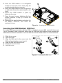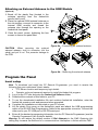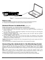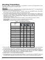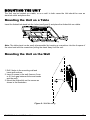
1
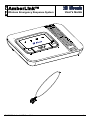
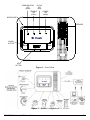
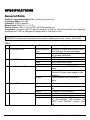
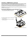
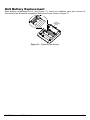
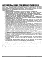
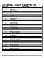
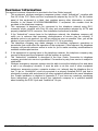
USER GUIDE A m b e r L i n k W i re l e s s E m e rg e n c y R e s p o n s e S y s t e m www.visonic.com AmberLink™ Wireless Emergency Response System User's Guide Mode el Canc D-303166 AmberLink™ User Guide 1 WARRANTY Visonic Limited (the “Manufacturer") warrants this product only (the "Product") to the original purchaser only (the “Purchaser”) against defective workmanship and materials under normal use of the Product for a period of twelve (12) months from the date of shipment by the Manufacturer. This Warranty is absolutely conditional upon the Product having been properly installed, maintained and operated under conditions of normal use in accordance with the Manufacturers recommended installation and operation instructions. Products which have become defective for any other reason, according to the Manufacturers discretion, such as improper installation, failure to follow recommended installation and operational instructions, neglect, willful damage, misuse or vandalism, accidental damage, alteration or tampering, or repair by anyone other than the manufacturer, are not covered by this Warranty. The Manufacturer does not represent that this Product may not be compromised and/or circumvented or that the Product will prevent any death and/or personal injury and/or damage to property resulting from burglary, robbery, fire or otherwise, or that the Product will in all cases provide adequate warning or protection. The Product, properly installed and maintained, only reduces the risk of such events without warning and it is not a guarantee or insurance that such events will not occur. THIS WARRANTY IS EXCLUSIVE AND EXPRESSLY IN LIEU OF ALL OTHER WARRANTIES, OBLIGATIONS OR LIABILITIES, WHETHER WRITTEN, ORAL, EXPRESS OR IMPLIED, INCLUDING ANY WARRANTY OF MERCHANTABILITY OR FITNESS FOR A PARTICULAR PURPOSE, OR OTHERWISE. IN NO CASE SHALL THE MANUFACTURER BE LIABLE TO ANYONE FOR ANY CONSEQUENTIAL OR INCIDENTAL DAMAGES FOR BREACH OF THIS WARRANTY OR ANY OTHER WARRANTIES WHATSOEVER, AS AFORESAID. THE MANUFACTURER SHALL IN NO EVENT BE LIABLE FOR ANY SPECIAL, INDIRECT, INCIDENTAL, CONSEQUENTIAL OR PUNITIVE DAMAGES OR FOR LOSS, DAMAGE, OR EXPENSE, INCLUDING LOSS OF USE, PROFITS, REVENUE, OR GOODWILL, DIRECTLY OR INDIRECTLY ARISING FROM PURCHASER’S USE OR INABILITY TO USE THE PRODUCT, OR FOR LOSS OR DESTRUCTION OF OTHER PROPERTY OR FROM ANY OTHER CAUSE, EVEN IF MANUFACTURER HAS BEEN ADVISED OF THE POSSIBILITY OF SUCH DAMAGE. THE MANUFACTURER SHALL HAVE NO LIABILITY FOR ANY DEATH, PERSONAL AND/OR BODILY INJURY AND/OR DAMAGE TO PROPERTY OR OTHER LOSS WHETHER DIRECT, INDIRECT, INCIDENTAL, CONSEQUENTIAL OR OTHERWISE, BASED ON A CLAIM THAT THE PRODUCT FAILED TO FUNCTION. 2 However, if the Manufacturer is held liable, whether directly or indirectly, for any loss or damage arising under this limited warranty, THE MANUFACTURER'S MAXIMUM LIABILITY (IF ANY) SHALL NOT IN ANY CASE EXCEED THE PURCHASE PRICE OF THE PRODUCT, which shall be fixed as liquidated damages and not as a penalty, and shall be the complete and exclusive remedy against the Manufacturer. When accepting the delivery of the Product, the Purchaser agrees to the said conditions of sale and warranty and he recognizes having been informed of. Some jurisdictions do not allow the exclusion or limitation of incidental or consequential damages, so these limitations may not apply under certain circumstances. The Manufacturer shall be under no liability whatsoever arising out of the corruption and/or malfunctioning of any telecommunication or electronic equipment or any programs. The Manufacturers obligations under this Warranty are limited solely to repair and/or replace at the Manufacturer’s discretion any Product or part thereof that may prove defective. Any repair and/or replacement shall not extend the original Warranty period. The Manufacturer shall not be responsible for dismantling and/or reinstallation costs. To exercise this Warranty the Product must be returned to the Manufacturer freight prepaid and insured. All freight and insurance costs are the responsibility of the Purchaser and are not included in this Warranty. This warranty shall not be modified, varied or extended, and the Manufacturer does not authorize any person to act on its behalf in the modification, variation or extension of this warranty. This warranty shall apply to the Product only. All products, accessories or attachments of others used in conjunction with the Product, including batteries, shall be covered solely by their own warranty, if any. The Manufacturer shall not be liable for any damage or loss whatsoever, whether directly, indirectly, incidentally, consequentially or otherwise, caused by the malfunction of the Product due to products, accessories, or attachments of others, including batteries, used in conjunction with the Products. This Warranty is exclusive to the original Purchaser and is not assignable. This Warranty is in addition to and does not affect your legal rights. Any provision in this warranty which is contrary to the Law in the state or country were the Product is supplied shall not apply. Warning: The user must follow the Manufacturer’s installation and operational instructions including testing the Product and its whole system at least once a week and to take all necessary precautions for his/her safety and the protection of his/her property. 1/08 D-303166 AmberLink™ User Guide Table of Contents WIRELESS EMERGENCY RESPONSE SYSTEM .............................................. 4 SPECIFICATIONS ............................................................................................... 6 General Data ........................................................................................................................... 6 Physical Properties ................................................................................................................. 7 SYSTEM SETUP ................................................................................................. 7 Select Unit Location ................................................................................................................ 7 Connect the Unit to your Telephone Line ............................................................................... 7 Installing a GSM Module (optional) ......................................................................................... 9 Program the Panel ................................................................................................................ 11 Connect Power to AmberLink (see Fig. 3b) .......................................................................... 12 Connecting the AmberLink to the Monitoring Center ............................................................ 12 Enrolling Transmitters ........................................................................................................... 13 Deleting Wireless Transmitters from the System Memory.................................................... 14 Wireless Devices Test........................................................................................................... 14 Reset to Factory Default ....................................................................................................... 14 MOUNTING THE UNIT ...................................................................................... 15 Mounting the Unit on a Table (Fig. 4) ................................................................................... 15 Mounting the Unit on the Wall ............................................................................................... 15 Using your AmberLink ..................................................................................... 16 Using your Pendant Transmitter ........................................................................................... 16 Calling for Emergency Assistance ........................................................................................ 16 Trouble .................................................................................................................................. 17 Remote control by telephone ................................................................................................ 17 MAINTAINING YOUR SYSTEM ........................................................................ 18 Pendant transmitter Test ....................................................................................................... 18 When a Pendant's Battery is Low ......................................................................................... 18 When a Smoke Detector's Battery is Low ............................................................................. 18 Unit Battery Replacement .....................................................................................................19 APPENDIX A: HOME FIRE ESCAPE PLANNING ............................................ 20 APPENDIX B: SIA EVENT CODES .................................................................. 21 APPENDIX C: CONTACT ID EVENT CODES .................................................. 21 APPENDIX D: COMPLIANCE and STATEMENTS .......................................... 23 Compliance ........................................................................................................................... 23 Statement .............................................................................................................................. 23 Statement .............................................................................................................................. 23 APPENDIX E: CUSTOMER PREMISES EQUIPMENT AND WIRING .............. 24 Customer Information ............................................................................................................ 25 D-303166 AmberLink™ User Guide 3 WIRELESS EMERGENCY RESPONSE SYSTEM Congratulations on your purchase of the wireless AmberLink™ Personal Emergency Response system. This home health care signaling system was designed to support people in their home environment. In the event of an emergency, help can be summoned at the press of a button and that same message can be sent to private numbers that you have selected for notification. In the event of fire, the system can be programmed to automatically call the monitoring station or to private phones. Local and Remote Programming may be performed over telephone and GSM connections. The Unit's LEDs show the system status. The Unit's rechargeable backup battery provides backup operation. When AC power is restored, the backup battery is automatically recharged. What's Included Before you begin to set up your system, make sure you have all the necessary components. AmberLink Unit Transformer Input 120VAC 60 Hz / Output 9VAC 0.1A Pendant transmitters supplied with necklace Additional Accessories (Optional) USB Programming Cable or RS-232 Dual Programming Cable and Adaptor Supervised wireless smoke detector (MCT-426) Waterproof arm/disarm security activation pendant transmitter (MCT-201 WP) Fully supervised indoor, PowerCode, flood detector (MCT-550) Wristband supplied for (MCT-212) Pet-Immune PowerCode wireless PIR motion detector (NEXT K9-85) Supervised PowerCode magnetic contact transmitter (MCT-302) Microprocessor controlled wireless repeater (MCX600PERS) Supervised wireless emergency button (MCT-220) The system unit is shown in Figure 1. Note: All of the listed transmitters have a PERS suffix. In addition, the "txid" code of each transmitter is printed on the packaging. Note: PowerCode refers to Visonic's proprietary communications protocol which makes use of unique ID codes. 4 AmberLink MCT-212 MCT-211 MCT-550 (Flood Detector) MCT-426 MCT-442 MCT-201 WP RS-232 Dual Programming Cable NEXT K9-85 MCT-302 MCT-220 D-303166 AmberLink™ User Guide COMMUNICATION LED (Green) STATUS LED (Red) TROUBLE LED (Yellow) POWER LED (Green) MICROPHONE SPEAKER CANCEL BUTTON Cancel Mode HELP BUTTON Figure 1 – Front View Figure 2 – System Configuration D-303166 AmberLink™ User Guide 5 SPECIFICATIONS General Data Pendant Transmitter Battery Life: 6 years (for typical use) Frequency (MHz): 315, 868. Indicators: 4 LED indicators. Battery Pack: NI-MH 7.2 V, 1.3 Ah Electric Power: 9VAC/0.1A (via 120VAC/60Hz transformer). Compliance: Complies with FCC part 68 and part 15, and UL 1637 Home Health Care Signaling Equipment. MCT-426 is designed to comply with UL 268 and UL 985. The system shall be installed in accordance with Chapter 2 of the National Fire Alarm Code, ANSI/NFPA 72 (National Fire Protection Association, Batterymarch Park, Quincy, MA 02269). LEDs: Indicator 1 RF Indication LED 2 Trouble LED 3 Communication LED Behavior Significance Lights steadily for Received RF signal with strong or good 3 sec. RSSI from any enrolled transmitter. Blinks Received RF signal with poor RSSI from any enrolled transmitter. No light No RF signal received. Lights steadily Indicates system trouble. Blinks When GSM RSSI is poor. No light No trouble. Light steadily Communication via PSTN/GSM is online. Blinks Phone line failure or is disconnected (Trouble LED also lights steadily in this condition). No light Communication via PSTN/GSM is offline. 4 Power LED 5 Backlight LEDs 6 Lights steadily AC power is connected. Blinks AC power is connected but battery is low. AC power is not connected. When the conditions below do not exist. When there is AC failure. When red indication LED blinks. The left backlight LED between the "HELP" and "CANCEL" buttons turns OFF. No light Lights steadily Blinks No light D-303166 AmberLink™ User Guide Special Functions: - Calling for help by using an emergency pendant transmitter - Speakerphone (hands-free) when communicating with Monitoring Center or when answering an incoming call by pressing the pendant - The system supports up to 28 users (pendant transmitters and smoke detectors). - Computer control and data download/upload - Remote control by telephone - Remote diagnostic and event log using PC software Physical Properties Operating Temperature: 32F to 104F (0C to 40C) Storage Temperature: -4F to 140F (-20C to 60C) Size: 9-13/16 x 7-1/4 x 2-5/16 in. (248 x 185 x 55 mm). Weight: 3 lb (1.35 kg) Color: Off-white Note: The product supports all standard monitoring center receivers. SYSTEM SETUP To set up your system, follow the steps below. Select Unit Location If possible, select a central location in your home for the Unit. This location should be in the area where you spend most of your time. The location should also enable an optimal signal reception for pendants and smoke detectors. The Unit can be placed on a table, desk, or counter. It also can be mounted on a wall. Make sure that the location you have selected is near an electrical outlet and a phone jack. Connect the Unit to your Telephone Line The AmberLink communicates with your Monitoring Center through your telephone line. 1. Locate the phone jack on your wall where you want to connect your AmberLink. If a phone is already plugged into that jack, unplug it and connect it to the "PHONE" connector on the back of the AmberLink. Your telephone will still function normally. 2. Connect the wide end (RJ-45) of the phone cord to the "Wall Jack" on your AmberLink. Plug the narrow end (RJ-11) of that phone cord into the phone jack on your wall. The AmberLink is now connected to your telephone line. Note: Be aware of other phone line services such as DSL. If DSL service is present on the phone line, you must install a filter. See Figures 3a and 3b for proper installation. D-303166 AmberLink™ User Guide 7 POWER CORD SAFETY CATCH TURN THE SAFETY CATCH SCREW IN THE DIRECTION SHOWN Figure 3a Battery Pack Lift plastic cover and insert computer cable 120 VAC 120 mA AC 12 VAC 1 A Figure 3b – Installation: Power, Telephone and Tel. line battery Connection Note: It is recommended that the AC power input, the Remote Programmer computer connection, and the telephone be interconnected within the same room. 8 D-303166 AmberLink™ User Guide Installing a GSM Module (optional) As an option, an internal GSM 350 module enables the AmberLink system to operate over a GSM cellular network. AmberLink connects over GSM to the Central Monitoring Station (CMS), therefore allowing you to send reports to the CMS and SMS messages to other private phone users. The GSM modem auto detection feature enables automatic enrollment of the GSM modem into the AmberLink panel memory. GSM modem auto detection is activated after reset (device power-up). CAUTION: Make sure that the AmberLink panel is powered OFF and disconnected from the mains power before opening the panel. Inserting the GSM Module into the AmberLink Panel 1 1. Open the battery enclosure on the back cover, disconnect the battery and remove it. Figure 4a – Removing the battery 2. Loosen and remove the four screws which secure the panel. 3. Remove the back panel cover and place it aside temporarily. 2 2 3 2 2 Figure 4b – Removing the back panel cover D-303166 AmberLink™ User Guide 9 4. Insert the GSM module to its designated location on the front cover. First, plug the module pins into the pin connector. 5. Lower the GSM module so that the grooves on both sides fit onto the rails situated on the cover. 6. Secure the GSM module in place by tightening its screw. 7. Close the panel covers, tightening the four screws (removed in step 2) to secure the panel shut. 8. Reconnect the panel’s battery and return it to the battery enclosure, and close the enclosure’s cover. 6 5 4 Figure 4c – Inserting the GSM module Inserting the GSM Module’s SIM Card To enable GSM communication with the CMS, a standard universal SIM card with Voice and Text in “Activated” state is required. Make sure the SIM card has sufficient voice minutes and SMS allowance before installation. Insert the SIM card into the GSM module as described below. 1. Slide the top cover. 2. Open the cover. 3. Align the SIM card to the cover (note the SIM card’s orientation as you insert it. 4. Slide the SIM card into the cover. 5. Rotate the cover to close. 6. Lock the cover. 3 1 2 4 5 6 Figure 5 – Inserting the SIM card 10 D-303166 AmberLink™ User Guide Attaching an External Antenna to the GSM Module (Optional) 1. Break off the plastic flap (located in the antenna opening) from the AmberLink panel’s back cover. 2. Place the optional GSM external antenna on the site surface, connect its connector to the internal GSM module and thread the antenna wire through the opening on the AmberLink front panel. 3. Close the panel covers, tightening the four screws to secure the panel shut. 3 1 2 Figure 6a – Connecting an external antenna CAUTION: When removing the optional external antenna, hold its connector (not the cable) and pull it out. This prevents damage to the PCB. Figure 6b – Removing the external antenna Program the Panel Local setup Note: To download and install the PC Remote Programmer, you need to receive the following from your authorized Visonic dealer: FTP Server location and temporary login details Operator code and password required to install the AmberLink program. 1. Log in to the FTP site and enter the AmberLink Software folder. 2. Download the contents of this folder to your PC. 3. To run the downloaded installation file and continue AmberLink installation, enter the AmberLink operator code and password when prompted. 4. Complete the installation as instructed on your PC screen. 5. Lift the plastic Prog cover on the AmberLink panel and attach the USB programming cable or the RS-232 Dual Programming Cable to the appropriate connector. Connect the other end to your PC USB port or RS-232 serial port. 6. Enter all the desired programming information into the PC Remote Programmer (see the Remote Programmer User Guide for details). Warning: Do not reduce the default number of Dial Attempts to the CMS. Reducing this setting may increase the likelihood of a communications interruption or failure with the CMS. D-303166 AmberLink™ User Guide 11 Figure 7 – Connecting the RS-232/USB programming cable Remote setup 1. Enter all the desired programming information into the PC Remote Programmer. 2. Connect to the remote panel via a dial-up modem attached to the PC. Connect Power to AmberLink (see Fig. 3b) During normal operation, your AmberLink runs on electrical power. 1. Insert the plug on the power cord into the "AC" connector on the AmberLink. 2. Insert the safety catch tab horizontally into the hole to the right of the power cord plug, as shown in Figure 3a. 3. Turn the safety catch screw, observing the polarity of the arrow in Figure 3a, until facing the other hole. Then secure the screw. 4. Connect the AC/AC adapter into a nearby electrical outlet. DO NOT USE AN OUTLET CONTROLLED BY A WALL SWITCH. 5. Turn the ON/OFF switch to ON. The unit sends the Power On notification to the Central Station and a “Happy Tune” plays (when you turn the switch off, the unit sends a Power Off notification and you hear a “Sad Tune”). Caution: When the plug is removed the unit is disconnected from the mains supply and will run on the battery pack. When electrical power is supplied the green light on the front panel illuminates. Connecting the AmberLink to the Monitoring Center After you complete the steps above your AmberLink will automatically call your Central Station provided that your unit was programmed to report to Central Station (and not to private telephones). Once this feature has been tested, the operator must disconnect by pressing DTMF '99'. Note: Certain remote areas of your residence may lie outside the reception range of the AmberLink, resulting in the unit not being able to receive transmissions directly. In this case, a Repeater (MCX-600PERS) can be used to increase the AmberLink reception range. For further details, please contact the company from where the products were purchased. 12 D-303166 AmberLink™ User Guide Enrolling Transmitters By using a remote / local PC programmer, it is possible to enroll up to 28 transmitters in the AmberLink and to program the panel as well. Without PC: Up to 15 wireless devices / transmitters can be enrolled locally without a PC. The AmberLink will recognize the device type according to it's ID: 1. Press and hold for 6 seconds both the "CANCEL" button and the MODE button. All 4 LEDs should flash to indicate that the system is in programming mode. 2. To select the desired transmitter location (zone) number, click the MODE button (displays the next menu) or the "HELP" button (displays the previous menu) repeatedly until the desired transmitter location number is displayed (see Table below). Each press advances to the next location (zone) number (1 - 15). The LEDs lights combination indicates the Location / zone number, as shown in Table 1: Flashing light = Free location into which a transmitter can be enrolled. Steady light = Occupied location with an enrolled transmitter. Table 1 - Zone Number Indication LED ZONE No. 1 ON – – – 2 – ON – – 3 ON ON – – 4 – – ON – 5 ON – ON – 6 – ON ON – 7 ON ON ON – 8 – – – ON – ON 9 ON – 10 – ON – ON 11 ON ON – ON 12 – – ON ON 13 ON – ON ON 14 – ON ON ON 15 ON ON ON ON 16 (Global Zones clear) – – – – 3. When the LEDs of the desired location flash, activate the desired transmitter. A success beep should be heard and the proper LEDs combination (see Table 1) should stop flashing and light constantly. 4. To verify that the specific transmitter was properly enrolled, reactivate the transmitter once again and verify that all 4 LEDs flash once (in a sequential manner) and then the LEDs combination corresponding to the transmitter location return to light constantly as before. 5. Perform steps 3 - 5 for all other desired transmitters. 6. Exit from programming mode by pressing and holding for 6 seconds both the "CANCEL" button and the MODE button (automatic exit by time out will occur if no action is performed during 4 minutes). D-303166 AmberLink™ User Guide 13 Deleting Wireless Transmitters from the System Memory Using PC: By using a remote or local PC programmer, it is possible to delete enrolled wireless transmitters. Without PC: Locally (without PC), wireless transmitters can be deleted from the AmberLink memory, as follows: 1. Press and hold both the "CANCEL" button and the right MODE button for 6 seconds. All 4 LEDs should flash to indicate that the system is in programming mode. 2. To select the desired transmitter to be deleted, click the right MODE button repeatedly until the desired transmitter location number is displayed (see Table 1). Each press advances to the next location (zone) number (1 - 15). 3. To delete a selected transmitter, press and hold the "CANCEL" button for 3 seconds. As a result, the LEDs combination of the respective deleted location (see Table 1) will flash indicating the location is now free. 4. To delete all the transmitters in the AmberLink memory, press and hold the "CANCEL" button for 6 sec until ALL LEDs light approx. 2 sec then only the LED of zone 1 blinks and the system is ready for enrolling. Wireless Devices Test 1. Press and hold both the "CANCEL" button and the right MODE button for 6 seconds. All 4 LEDs should flash to indicate that the system is in programming mode/Test mode. 2. Activate the transmitter you wish to test and listen to the system response. If the signal level received by the system is "Strong" or "Good", the system will respond with a success beep and RF red LED will light up during transmission. If the signal level is "Poor" the system will respond with 2 sec. long beep and the RF green LED blinks. During the TEST mode, the system will not dial to the Central Station. 3. Exit the test by pressing and holding both the "CANCEL" button and the right MODE button for 6 seconds (automatic exit by timeout will occur if no action is performed during 4 minutes). Reset to Factory Default If you need to return to the preset factory default configuration, you can reset the panel to this configuration. 1. Press and hold both the "CANCEL" button and the right MODE button for 6 seconds. All 4 LEDs should flash to indicate that the system is in programming mode/Test mode. 2. Press the “CANCEL”, “HELP”, and “MODE” buttons simultaneously for an additional 8 seconds. At this point, the panel is reset to the factory default configuration. 14 D-303166 AmberLink™ User Guide MOUNTING THE UNIT The Unit can be located on a table, or on a wall. In both cases the Unit should be near an electrical outlet and phone line. Mounting the Unit on a Table Insert the AmberLink stand into the holes (see figure 8) and place the AmberLink on a table. Figure 8 – Table Stand Mounting Note: The table stand can be easily disassembled by inserting a screwdriver into the rib space of the stand and with the screwdriver pulling the stand away from the unit. Mounting the Unit on the Wall 1. Drill 2 holes in the mounting wall and insert wall anchors. 2. Insert 2 screws in the wall (leave a 5 mm or 0.2 inch gap between the screw heads and the wall). 3. Mount the AmberLink on the screws as shown in the illustration. Figure 9 - Wall Mounting D-303166 AmberLink™ User Guide 15 Using your AmberLink Your AmberLink is the communication center of your system. When your pendant transmitter or optional fall-detector/smoke detector signals the AmberLink, the AmberLink contacts your Monitoring Center or private phones to report the emergency event. Your AmberLink includes the following buttons. HELP – When pressed, an emergency alarm is reported to the Monitoring Center or to private phones. CANCEL – This button should be pressed to: - Stop dialing - Confirm a reminder - Reset the inactivity timer Using your Pendant Transmitter The pendant transmitter can be used to initiate an emergency call and also to answer incoming calls. Pendant Activation - Your pendant transmitter lets you signal to the AmberLink from anywhere in your home when you need emergency assistance. You should wear your pendant transmitter whenever you are at home even in the shower or bath. Your pendant transmitter is waterproof. Your pendant transmitter can be activated by simply pushing its red button. Once pushed, a signal is sent from the pendant transmitter to the AmberLink, the red LED on the pendant transmitter illuminates and a success beep is heard. The AmberLink then calls the Monitoring Center or a private phone. If your phone is ringing, pressing the pendant's red button once will answer the incoming call. You can then talk over the unit's speakerphone. To end the speakerphone call and hang up, simply press the pendant button again. Neckband - You can wear the pendant transmitter using the neckband. Slip the tab on the neckband into the slot on the pendant transmitter and fasten the tab. Optional Wristband - Your pendant transmitter can also be used with an optional wristband. To make the pendant transmitter wristband smaller, slide the pendant transmitter towards the buckle. To make the wristband larger, slide the pendant transmitter away from the buckle. Calling for Emergency Assistance If you need emergency assistance, press the button on your pendant transmitter or press the HELP button on your AmberLink. After you press the "HELP" button, you will hear a confirmation sound. The AmberLink calls your Monitoring Center or a private phone and sends an emergency alarm. When your Monitoring Center representative or the person on the private phone answers, you can hear them talking to you through the AmberLink. If you have a phone connected to the AmberLink and want to use the phone to talk with the representative, let the representative know and the Monitoring Center will return your call. 16 D-303166 AmberLink™ User Guide Trouble Trouble conditions are indicated when the Trouble LED lights steadily and beeps occur. The condition is immediately reported to the Monitoring Center. Yellow LED On Blinks Definition Low battery, AC failure, Line failure, Detector tamper, Inactivity GSM trouble (network failure, SIM card problem) Remote control by telephone Both the central station and any person to whom the AmberLink unit is dialing can perform a number of actions using the AmberLink unit, as follows: Pressed button 1 3 4 7 5 8 99 Performs Half duplex: speaker ON, microphone OFF Half duplex: microphone ON, speaker OFF Increase speaker volume (up to 4 levels) Decrease speaker volume (up to 4 levels) High ambient microphone level Low ambient microphone level Disconnect the call D-303166 AmberLink™ User Guide 17 MAINTAINING YOUR SYSTEM The transmitter may get dirty as it’s touched with your fingers. Clean it only with a soft cloth or sponge moistened lightly with a mixture of water and mild detergent, and wipe it dry immediately. The use of abrasives of any kind is strictly forbidden. Also, never use solvents such as kerosene, acetone or thinner. Note: The AmberLink system must be checked by a qualified technician at least once every three years. Pendant transmitter Test To test your pendant(s) regularly, your installer must enable this feature during configuration. At the scheduled time, the pendant’s LED blinks to instruct the user to press the Transmit button to confirm the test. LED indicator Transmit Button Loop Velcro strap Figure 10 – MCT-212 Pendant When a Pendant's Battery is Low When the MCT-212 pendant transmitter's battery is low, its LED flashes rapidly several times per second during transmission. When a Smoke Detector's Battery is Low When a smoke detector's battery voltage is low, the smoke detector alerts you by beeping every 35 seconds until replacement of the detector's battery. The smoke detector's batteries should last from 5 to 8 years, depending on the battery type. To replace the batteries, refer to the instructions provided with the smoke detector. 18 D-303166 AmberLink™ User Guide Unit Battery Replacement Open battery compartment cover (see Figure 11). Insert one 8-battery pack and connect its connector to the AmberLink receptacle. Route the wire as shown in Figure 11. Battery Compartment Cover Figure 11 – Replacing the Battery D-303166 AmberLink™ User Guide 19 APPENDIX A: HOME FIRE ESCAPE PLANNING The onset of a fire can often spread rapidly throughout your home, leaving you with little time to escape safely. Getting out of the house depends, largely, on advance warning from smoke detectors together with an advance planning strategy – namely, a home fire escape plan familiar to all members of your family and which has previously been put into practice. Perform the following steps: Make preparations with members of your family to conduct an evacuation plan. Draw a floor plan of your home, displaying two possible exit areas of each room, including windows. Don’t forget to mark the location of every installed smoke detector. Test all smoke detectors periodically (this must be performed in a qualified testing laboratory), to ensure their serviceability. Replace batteries as required. Make sure that everyone understands the escape plan and is able to recognize the sound emitted from the smoke alarm. Verify that the escape routes are clear and that doors and windows can be opened easily. If windows or doors in your home have security bars, make sure that the bars have quick-release mechanisms on the inside, which, in the event of an emergency, can be opened immediately. Quick release mechanisms do not compromise your security, but increase the likelihood of safely escaping a home fire. Practice the escape plan at least twice a year. It is important that all members of the family participate, especially children and grandparents. Allow children to master the fire escape planning procedure before holding a fire drill at night while they are asleep. The objective here is to perform a fire drill, and not to frighten the children, so informing the children of the fire drill before they go to bed can be as effective as a surprise drill. If children or others do not awaken promptly to the sound of the smoke alarm, or if there are infants or family members with mobility disabilities, make sure that someone is assigned to assist them in the fire drill and in the event of a real-life emergency. Agree on an outside meeting place where everyone can meet once safely out of the house premises. Remember to get out of the house first, and then to call for help. Never go back inside the house until authorized by the fire department. Ensure that all members of the family memorize the emergency phone number of the fire department. This will allow a member of the household to call for help from a cellular phone or from a neighbor’s home. Be fully prepared for a real fire: when a smoke alarm sounds, get out of the house immediately and do not return to the house until authorized to do so by the fire department! If you live in an apartment building, make sure that you are familiar with the building evacuation plan. In the event of a fire, use the stairs, never the elevator. Inform guests or visitors to your home about your family’s fire escape plan. When visiting other homes, ask the occupants about their escape plan, if they have one. If they do not, point out the importance of such a plan and offer to help them prepare one. This is particularly important when children attend “sleepovers” at friends' homes. Warning Owners Instructions Notice: Smoke detectors shall not be removed by anyone except by occupants. 20 D-303166 AmberLink™ User Guide APPENDIX B: CONTACT ID EVENT CODES EVENT CODE EVENT DESCRIPTION 000 COMMUNICATION LOSS 101 EMERGENCY 105 MISSED REMINDER 110 FIRE 121 DURESS 137 TAMPER - CONTROL PANEL 151 GAS ALARM 152 EXTREME FREEZING CONDITIONS 153 FREEZING (0° C/32°F) 154 FLOOD ALARM 158 HOT TEMPERATURE 159 COLD TEMPERATURE 301 RESTORE AC POWER 302 LOW BATTERY – CONTROL PANEL 308 SYSTEM SHUTDOWN 311 BATTERY DISCONNECTED 344 RF RECEIVER JAMMING 350 COMMUNICATION RESTORE 351 TELEPHONE LINE TROUBLE 373 FIRE DETECTOR TROUBLE 380 GAS TROUBLE 380 PROBE TROUBLE 381 LOSS OF SUPERVISION 383 TAMPER - SENSOR 384 LOW BATTERY – TRANSMITTER 393 FIRE DETECTOR NEEDS CLEANING 401 SYSTEM ARMED – AWAY 441 SYSTEM ARMED – HOME 459 RECENT CLOSE EVENT 602 PERIODIC TEST REPORT 612 PENDANT TEST UNSUCCESSFUL 641 SENIOR WATCH TROUBLE 654 SYSTEM INACTIVE D-303166 AmberLink™ User Guide 21 APPENDIX C: SIA EVENT CODES EVENT CODE ZONE # QA 35 EMERGENCY ALARM (CONSOLE) RP 35 PERIODIC TEST NA 35 INACTIVITY ALARM AT 35 A/C LOSS AR 35 A/C LOSS RESTORE YT 35 LOW BATTERY TO CONSOLE YR 35 RESTORAL TO LOW BATTERY TO CONSOLE YM 35 SYSTEM BATTERY MISSING YS 35 SYSTEM SHUTDOWN (POWER OFF THE UNIT) RR 35 POWER UP (POWER ON THE UNIT) MI 35 MISSED REMINDER L_ 90 LISTEN IN (OPEN TWO WAY VOICE SESSION) AB 35 ALARM CANCELLED (RESET BUTTON ON CONSOLE PUSHED) XX 22 EVENT DESCRIPTION PENDANT TEST FAILURE XT LOW BATTERY TO TRANSMITTER XR RESTORAL TO LOW BATTERY TO TRANSMITTER XS TRANSMITTER LOST SUPERVISION XJ RESTORAL TO TRANSMITTER LOST SUPERVISION TA TAMPER ALARM TR TAMPER RESTORE MA MEDICAL ALARM (NECK PENDANT AND WATCH) MT MEDICAL TRANSMITTER LOW BATTERY MR RESTORAL TO MEDICAL TRANSMITTER LOW BATTERY GA GAS ALARM GT GAS SENSOR LOW BATTERY GR RESTORAL TO GAS SENSOR LOW BATTERY GS GAS SENSOR LOST SUPERVISION GJ RESTORAL TO GAS SENSOR LOST SUPERVISION FA FIRE ALARM FH FIRE ALARM RESTORE FT FIRE SENSOR LOW BATTERY FR RESTORAL TO FIRE SENSOR LOW BATTERY FS FIRE SENSOR LOST SUPERVISION FJ RESTORAL TO FIRE SENSOR LOST SUPERVISION WA FLOOD ALARM WT FLOOD ALARM SENSOR LOW BATTERY WT FLOOD ALARM SENSOR LOW BATTERY WR RESTORAL TO FLOOD ALARM SENSOR LOW BATTERY WS FLOOD ALARM SENSOR LOST SUPERVISION WJ RESTORAL TO FLOOD ALARM SENSOR LOST SUPERVISION D-303166 AmberLink™ User Guide APPENDIX D: COMPLIANCE and STATEMENTS Compliance § 15.19(a)(3) AmberLink This device complies with Part 15 of the FCC Rules. Operation is subject to the following two conditions: (1) This device may not cause harmful interference, and (2) this device must accept any interference received, § 15.21 Statement Changes or modifications to this equipment not expressly approved by the party responsible for compliance could void the user’s authority to operate the equipment. 5. For a Class B digital device the instructions furnished the user shall include the following or similar statement, placed in a prominent location in the text of the user or instruction manual: § 15.105 Statement NOTE: This equipment has been tested and found to comply with the limits for a Class B digital device, pursuant to part 15 of the FCC Rules. These limits are designed to provide reasonable protection against harmful interference in a residential installation. This equipment generates, uses and can radiate radio frequency energy and, if not installed and used in accordance with the instructions, may cause harmful interference to radio communications. However, there is no guarantee that interference will not occur in a particular installation. If this equipment does cause harmful interference to radio or television reception, which can be determined by turning the equipment off and on, the user is encouraged to try to correct the interference by one or more of the following measures: -Reorient or relocate the receiving antenna. -Increase the separation between the equipment and receiver. -Connect the equipment into an outlet on a circuit different from that to which the receiver is connected. -Consult the dealer or an experienced radio/TV technician for help. Due to FCC requirements in the U.S.A. and IC in Canada, transmission power is limited. This limited power output should provide a maximum operating range of 400 feet in "open space". This range may be reduced further when operating within buildings, or around other obstructions to R.F. signals. Other operating frequencies as approved for use in other parts of the world have a higher allowed transmission power which can result in greater range. This equipment should be installed in accordance with Chapter 2 of the National Fire Alarm Code, ANSI/NFPA 72. D-303166 AmberLink™ User Guide 23 APPENDIX E: CUSTOMER PREMISES EQUIPMENT AND WIRING The REN is used to determine the number of devices that may be connected to a telephone line. Excessive RENs on a telephone line may result in the devices not ringing in response to an incoming call. In most but not all areas, the sum of RENs should not exceed five. To be certain of the number of devices that may be connected to a line, as determined by the total RENs, contact the local telephone company. The REN of an alarm system is part of the product identifier that has the format US: VSOAL01BANBERGSLA. 1 2 DSL FILTER RJ-31X CORD TO LINE JACK For locations with DSL service 3 RJ-31X JACK 8 7 6 4 TEL LINES 5 Note: For whole house line seizure with DSL service present on the phone line, you must install a filter. It is suggested to use the DSL alarm filter model Z-A431PJ31X manufactured by Excelsus Technologies, or equivalent. This filter simply plugs into the RJ-31X jack and allows alarm reporting without breaking the internet connection. 24 D-303166 AmberLink™ User Guide Customer Information The required customer information is provided in the User Guide (manual). 1. This equipment, wireless emergency response system, model “AmberLink”, complies with Part 68 of the FCC Rules and the requirements adopted by the ACTA. On the bottom panel of this equipment is a label, that contains among other information, a product identifier in the format US:VSOAL00BAMBERNA. If requested, this number must be provided to the telephone company. 2. This equipment is designed to be connected to the telephone network using RJ11 connector which complies with Part 68 rules and requirements adopted by ACTA and properly installed RJ31X connector. See Installation Instructions for details. 3. If the “AmberLink” causes harm to the telephone network, the telephone company will notify you in advance that temporary discontinuance of service may be required. If advance notice is not practical, you will be notified as soon as possible. Also, you will be advised of your right to file a compliant with the FCC if it is necessary. 4. The telephone company may make changes in its facilities, equipment, operations or procedures that could affect the operation of the equipment. If this happens, the telephone company will provide advance notice in order for you to make necessary modifications to maintain uninterrupted service. 5. If the equipment is causing harm to the telephone network, the telephone company may request to disconnect the equipment until the problem is resolved. 6. The “AmberLink” installation is described in the User Guide. Connection to telephone company provided coin service is prohibited. Connection to party lines service is subject to state tariffs. 7. Wireless emergency response system must be able to seize the telephone line and place a call in an emergency situation. It must be able to do this even if other equipment (telephone, answering system, computer modem, etc.) already has the telephone line in use. To do so, “AmberLink” must be connected to a properly installed RJ31X jack that is electrically in series with and ahead of all other equipment attached to the same telephone line. Proper installation is depicted in Appendix E. If you have any questions concerning these instructions, you should consult your telephone company or a qualified installer about installing the RJ31X jack and “AmberLink” for you. D-303166 AmberLink™ User Guide 25 26 D-303166 AmberLink™ User Guide D-303166 AmberLink™ User Guide 27 W.E.E.E. Product Recycling Declaration For information regarding the recycling of this product you must contact the company from which you orignially purchased it. If you are discarding this product and not returning it for repair then you must ensure that it is discarded as specified by your supplier. This product is not to be thrown away with everyday waste. Directive 2002/96/EC Waste Electrical and Electronic Equipment. E-MAIL: [email protected] INTERNET: www.visonic.com VISONIC LTD. 2013 D-303166 AmberLink™ USER GUIDE 28 Rev 5, 07/13 D-303166 AmberLink™ User Guide Contact Visonic for further information: Email: [email protected] Tel: +972 3 6456789 USER GUIDE © 2013 Visonic Ltd. All rights reserved. AmberLink English User Guide D-303166