1
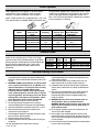
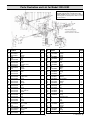
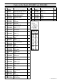
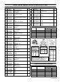
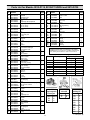
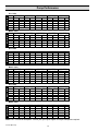
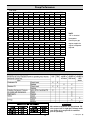
Drive Options
Order appropriate Shaft Adapter Kit for drive option
requirements. Refer to adjoining chart for proper
selection. For proper installation, refer to Page 5.
9910-D250 are supplied with a splined thru shaft. These
models can be adapted for belt and pulley drive with the
use of a split taper bushing (Hypro part number 31150011). Use of this bushing allows a Browning Q2 sheave
to be mounted on the bushing.
NOTE: Model 9910-D135 is supplied with a 1-3/8" male
PTO splined shaft as standard. Models 9910-D160 and
Pump
Model
9910-D70
9910-D115
9910-D135
9910-D160
9910-D250
1-3/8" Male
1" Solid Shaft
Splined PTO
w/Keyway
Shaft
9910-KIT1710
9910-KIT1711
9910-KIT1710
9910-KIT1711
Std. 1-3/8"
male-splined shaft
N/A
Std. thru shaft
N/A
Std. thru shaft
N/A
1-3/8" Female
Splined PTO
Coupler
9910-KIT1708
9910-KIT1708
Control Units
Control units are available for easy flow and pressure
control of your spraying system. These units include
a pressure relief valve to control pressure, an oil-filled
pressure gauge to monitor pressure, and multiple outlet
shut-off valves to control boom flow. Refer to the
adjoining chart to select the proper control unit for
your pump.
Control
Unit Model
3300-0082
3300-0087
3300-0088
N/A
N/A
N/A
Max
GPM
66
42.5
42.5
General Safety Information
1. Use of a pressure relief device on the discharge side of pump
is required to prevent damage from pressure build up if the
discharge is closed or blocked while the power source is still
running.
2. WARNING: DO NOT pump flammable or explosive fluids
such as gasoline, fuel oil, kerosene, etc. DO NOT use in
explosive atmospheres. The pump should be used only
with liquids that are compatible with the pump
component materials. DO NOT pump asphalt, asphalt
sealer, roofing compounds, concrete sealers or any twostep curing products. Personal injury may result, and the
warranty will be void. If there are any questions, call the
Hypro Applications toll-free number: 800-445-8360.
3. Do not operate pump above recommended rpm.
4. Do not pump at pressures higher than the maximum
recommended pressures for the pump (see Specifications).
5. Operate pump between temperature range of 45˚ to 140˚ F.
6. Make certain that the power source conforms to the
requirements of your equipment.
7. Provide adequate protection in guarding around the moving
parts, such as the shaft and pulleys.
8. Disconnect power before servicing.
9. Release all pressure within the system before servicing any
component.
10. Drain all liquids from the system before servicing.
L-1381 (Rev. B)
2
Hydraulic
Motor Mounting
Flange Kits
9910-HYD2495
9910-HYD2495
N/A
9910-HYD1570
9910-HYD1570
Max
PSI
290
290
290
Type
D250
D70, D115, D135, D160
D70, D115, D135, D160
11. Secure the discharge lines before starting the pump. An
unsecured discharge line may whip, causing personal injury
and/or property damage.
12. Check hoses for weak or worn condition before each use.
Make certain that all connections are tight and secure.
13. Periodically inspect the pump and the system components.
Perform routine maintenance as required (see Maintenance
section).
14. When wiring an electrically-driven pump, follow all electrical
and safety codes, as well as the most recent National
Electrical Code (NEC) and the Occupational Safety and
Health Act (OSHA).
15. WARNING: Because of the risk of electrical shock, all
wiring should be done by a qualified electrician.
WARNING: DO NOT handle a pump or pump motor with
wet hands, when standing on a wet or damp surface, or
while standing in water.
16. Do not operate a gasoline engine in an enclosed area. Be
sure the area is well ventilated.
17. Use only pipe, hose and fittings rated for maximum rated
pressure of pump or pressure at which pressure relief valve is
set at. Check with local supplier for proper pressure rating. Do
not use used pipe!
18. Do not use these pumps for pumping water or other liquids for
human or animal consumption.