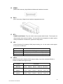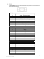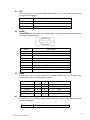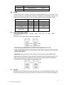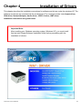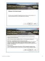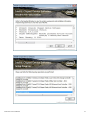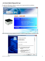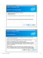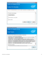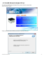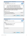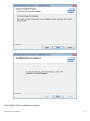
1
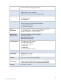
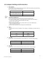
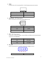
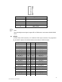
ACS-2695A Box PC User Manual Socket G2, 3rd Generation Intel Core i7/i5/i3 BOX PC Release Date Revision Aug. 2014 ® 2014 Aplex Technology, Inc. V1.01 All Rights Reserved. Published in Taiwan Aplex Technology, Inc. 15F-1, No.186, Jian Yi Road, Zhonghe District, New Taipei City 235, Taiwan Tel: 886-2-82262881 Fax: 886-2-82262883 E-mail: [email protected] URL: www.aplex.com.tw 1 ACS-2695A User Manual Warning!_____________________________ This equipment generates, uses and can radiate radio frequency energy and if not installed and used in accordance with the instructions manual, it may cause interference to radio communications. It has been tested and found to comply with the limits for a Class A computing device pursuant to FCC Rules, which are designed to provide reasonable protection against such interference when operated in a commercial environment. Operation of this equipment in a residential area is likely to cause interference in which case the user at his own expense will be required to take whatever measures may be required to correct the interference. Electric Shock Hazard – Do not operate the machine with its back cover removed. There are dangerous high voltages inside. Disclaimer This information in this document is subject to change without notice. In no event shall Aplex Technology Inc. be liable for damages of any kind, whether incidental or consequential, arising from either the use or misuse of information in this document or in any related materials. 2 ACS-2695A User Manual Packing List Accessories (as ticked) included in this package are: □ Adaptor □ Driver & manual CD disc □ Other.___________________(please specify) Safety Precautions Follow the messages below to avoid your systems from damage: ◆ Avoid your system from static electricity on all occasions. ◆ Prevent electric shock. Don‘t touch any components of this card when the card is power-on. Always disconnect power when the system is not in use. ◆ Disconnect power when you change any hardware devices. For instance, when you connect a jumper or install any cards, a surge of power may damage the electronic components or the whole system. 3 ACS-2695A User Manual Table of Contents___________________ Warning!……….…………………………………………………………….……..….2 Disclaimer…….…………………………………………………….…………………2 Packing List.......................................................................................................3 Safety Precautions............................................................................................3 Chapter 1 Getting Started 1.1 Specifications………………………...……….………….……...…..6 1.2 Dimensions……………………...…...……………….…………......7 1.3 Brief Description of ACS-2695A……………………………………8 1.4 Installation of HDD......................................................................9 1.5 Installation of PCI Add-on..........................................................10 Chapter 2 Hardware Installation 2.1 Mainboard Specifications……………………………….…………11 2.2 Jumpers Setting and Connectors……………………...…………16 Chapter 3 __ BIOS Setup 3.1 Operations after POST Screen.................................................30 3.2 BIOS SETUP UTILITY...............................................................30 3.3 Main Settings............................................................................31 3.4 Advanced Settings....................................................................32 3.5 Chipset Settings........................................................................38 3.6 Boot Settings.............................................................................43 3.7 Security Settings.......................................................................45 3.8 Save & Exit Settings..................................................................46 Chapter 4 _ Installation of Drivers 4.1 Intel Chipset Driver.……………………………..….………………47 4.2 Intel VGA Chipset Driver..…....…......…………………..…….......53 4.3 Intel Network Adapter Driver……………....................................57 4.4 Realtek Audio Driver Installation……………...………………..…60 4.5 Intel(R) USB 3.0 Driver Installation…………..............................62 4.6 Intel(R) AMT Installation……………………................................65 4 ACS-2695A User Manual Figures Figure 1.1: Dimensions of the ACS-2695A………….………………...7 Figure 1.2: Left-front View of ACS-2695A..……………………….......8 Figure 1.3: Right-front View of ACS-2695A……….………..……........8 Figure 2.1: Mainboard Dimensions………………...…………………11 Figure 2.2: Jumpers and Connectors Location-TOP……..…...……12 Figure 2.4: Jumpers and Connectors Location- Bottom……………13 5 ACS-2695A User Manual Chapter 1 Getting Started 1.1 Specifications Specs System ACS-2695A CPU System Chipset System Memory External I/O Port OS Support Expansion I/O By a new daughter board Wi-Fi CD/DVD-R Device Optional Fan Expansion Slots Storage Power Power Input Support Socket G2, 3rd Generation Intel Core i7/i5/i3 Intel HM77 PCH 2 x 204 Pin DDR3 SO-DIMM, default 4GB (one slot), up to 16GB 1066/1333MHz 2 x DB9 RS-232 (COM1.2) 1 x DVI-I 1 x HDMI 2 x RJ45 GbE LAN 4 x USB 2.0 1 x Mic-in, Line-Out 1 x DC Power 3 Pin terminal block connector 1 x 2 pin power switch connector 2X LED indication Windows XP embedded, Windows embedded standard 7, Windows 7 Pro for embedded By TB-523 1X Power button switch 1X CF Slot by USB 1X COM RS-422/485 (COM3, default:RS-485) 1X COM RS-232 (COM4) 1X10 pins terminal block for 1 Ground/VCC/ 4 in & out DIDO 2 optional Antenna holes at front side (conserved) Optional Two 40X40mm System Fan space, rear and front (080401030540) 1 x PCIe x16 and 1 x PCI slot By TB-526P1E161 2x 2.5" SATA HDD DC 9~32V Power Consumption Max:29.75W Mechanical Specifications Construction / Color Dimensions(WxHxD) Net Weight Environmental Operating Temperature Storage Temperature Storage Humidity Vibration Shock Drop Certificate Steel and Aluminum Heatsink 211.2(W)x203.5(H)x177(D) mm 5.5KG 0~50 °C -20~60 °C 10%~90%@ 40℃, non-condensing 5G, 5-500MHz, 3 Axes(with CF or SSD) 0.5G 5-500MHz, 3 Axes(with HDD) 50G Half sine (11 msec. duration)/operation with SSD 92cm (1 Corner, 3 Edge, 6 Surface) CE / FCC Class A 6 ACS-2695A User Manual 1.2 Dimensions Figure 1.1: Dimensions of the ACS-2695A 7 ACS-2695A User Manual 1.3 Brief Description of the ACS-2695A The ACS-2695A is a fan-less high-efficiency thermal solution Box PC, powered by Socket G2, 3rd Generation Intel Core i7/i5/i3 processor and supporting 4 x USB 2.0 ports, 2 x COM Ports, 1 x DVI-I, support 2 x SATA HDD space, 1 x external CF slot, 9~32V wide-ranging power input etc. It is ideal for Industrial Automation, Factory Automation, Machine Vision, Process Control, Data Terminal, TI, Surveillance, etc. and running factory operations from small visual interface and maintenance applications to large control process applications. The ACS-2695A works very well along with any of our Display series and it absolutely can provide an easy way to perform control and field maintenance. Figure 1.2: Left-front View of ACS-2695A Figure 1.3: Right-front View of ACS-2695A 8 ACS-2695A User Manual 1.4 Installation of HDD Step 1 There is one screw which connects to the chassis. Pull out the chassis towards the I/O side after unscrewing as shown in the picture ACS-2695A Step 2 There are 2 screws to deal with when enclosing or removing the HDD bracket as shown in the picture ACS-2695A Loosen screw and draw the HDD bracket out as shown in the picture ACS-2695A Step 3 Tighten the 1 screw as shown in the picture. That’s how it should look after it has been installed. 9 ACS-2695A User Manual 1.5 Installation of PCI Add-on Step 1 There is one screw which connects to the chassis. Pull out the chassis towards the I/O side after unscrewing as shown in the picture ACS-2695A Step 2 Now slide the add on into the PCI slot, making sure the golden part faces the slot. When the part that is interfaced together come into the right contact, slightly push the add on into the rail of the slot. After sliding the add on into the PCI expansion slot, get the one screw as circled tightened to finish the connection. ** Half Expansion-card limit to be not more than 175mm length Step 3 Tighten the 1 screw as shown in the picture. That’s how it should look after it has been installed. 10 ACS-2695A User Manual Chapter 2 Hardware Installation 2.1Mainboard Specifications Figure 2.1: Mainboard Dimensions 11 ACS-2695A User Manual Figure 2.2: Jumpers and Connectors Location-TOP 12 ACS-2695A User Manual Figure 2.3: Jumpers and Connectors Location- Bottom 13 ACS-2695A User Manual Specifications Specifications Board Size 170mm x 170mm CPU Support Support Socket G2, 2nd/3rd Gen Intel Core i3/i5/i7 Processors Chipset Intel HM77 (ASB-M8771HB) Memory Support 2 x SO-DIMM (204pins), up to 16GB DDRIII 1066/1333/1600MHz FSB Graphics Intel HD Graphics 4000 Super I/O Winbond W83627UHG BIOS AMIBIOS 16M Storage 1 x SATA2.0 Connector 1 x SATA2.0 Connector 2 x SATA3.0 Connector 1 x MSATA Connector Ethernet 2 x PCIe GbE LAN by Intel 82574L USB 4 x USB 2.0 stack ports for external 3 x USB 2.0 box Pin header for MIO1 4 x USB 2.0 box Pin header for MIO2 1 x USB 2.0 internal for mini PCIe Serial Digital I/O (SATA3) (SATA4 option) (SATA1/SATA2) (option) 1 x RS232/422/485 port, DB9 connector for external (COM1) pin 9 w/5V/12V/Ring select 1 x RS232 port, DB9 connector for external (COM2) pin 9 w/5V/12V/Ring select 1 x RS232 header for internal (COM5) 1 x RS232 header for internal (COM6), pin 9 w/5V/12V select I/O Card TB-522 (option): 1 x 422/485 select header for internal MIO1 (COM3) 1 x RS232 header for internal MIO1 (COM4) I/O Card TB-523 (option): 1 x 422/485 select header for internal MIO1 (COM3) 1 x RS232/422/485 select header for internal MIO1 (COM4) 8-bit digital I/O by Pin header by MIO2 4-bit digital Input 4-bit digital Output 14 ACS-2695A User Manual Battery Support CR2477 Li battery by 2-pin header Support CR2032 Li battery (BAT2,option) Audio Support Audio via Realtek ALC662 HD audio codec Support Line-out, MIC by JACK1 Support Line-in, Line-out, MIC by 2x6-pin header Keyboard /Mouse PS2 K/B and Mouse by MIO2 1 x PS/2 keyboard 1 x PS/2 mouse Expansion 1 x PCI-express x16 extend by 4x30 pin socket 2 x PCI-express x1 extend by 4x10 pin socket 1 x mini-PCI-express slot 1 x CRT 2x5 Pin Header Power Management 1 x 3-pin power input connector (Wide range DC+9V~32V) 1 x ATX Power Input (2x2Pin and 3Pin, option) DC5V/12V output by 1x4 pin Connectors Switches and LED Indicators Power on/off switch by TB-522 or TB-523 Reset switch by MIO2 Power LED status by MIO2 HDD LED status by MIO2 External I/O port 2 x COM Ports (COM1/COM2) 4 x USB 2.0 Ports (stack) 2 x RJ45 GbE LAN Ports 1 x DVI-I Port 1 x HDMI Port 1 x Audio Ports (Mic, Line out) Watchdog Timer Software programmable 1–255 second by Super I/O Temperature Operating: -20℃ to 70℃ Storage: -40℃ to 85℃ Humidity 10% - 90%, non-condensing, operating Power Consumption 12V/3.80A (Intel i5-2430M 2.4GHz Processor with 4GB DDR3) 19V/2.0A (Intel i5-2540 2.6GHz Processor with 8GB DDR3) 19V/2.2A(Intel i7-2620 2.7GHz Processor with 8GB DDR3) EMI/EMS Meet CE/FCC class A 15 ACS-2695A User Manual 2.2 Jumpers Setting and Connectors 1. RTC1/SRTC1: (2.0mm Pitch 1X2 Pin Header)CMOS clear jumper, CMOS clear operation will permanently reset old BIOS settings to factory defaults. RTC1/SRTC1 CMOS Open or (RTC1Pin1-SRTC1 Pin close) NORMAL (Default) Close 1-2 Clear CMOS Procedures of CMOS clear: a) Turn off the system and unplug the power cord from the power outlet. b) To clear the CMOS settings, use the jumper cap to close pins1 and 2 for about 3 seconds then reinstall the jumper clip back to pins open. c) Power on the system again. d) When entering the POST screen, press the <DEL> key to enter CMOS Setup Utility to load optimal defaults. e) After the above operations, save changes and exit BIOS Setup. 2. BAT1 : (1.25mm Pitch 1X2 box Pin Header) 3.0V Li battery is embedded to provide power for CMOS. Pin# Signal Name Pin1 VBAT Pin2 Ground 3. PS_SEL: (2.0mm Pitch 1X3 Pin Header),DC in Power and ATX 12V_IN Power jumper setting. PS_SEL Mode Close 1-2 DC in Power (Default) Close 2-3 ATX 12V_IN Power 4. PS_ON: (2.0mm Pitch 1X2 Pin Header),ATX Power and Auto Power on jumper setting. PS_ON Mode Close 1-2 Auto Power on (Default) Open 1-2 ATX Power 16 ACS-2695A User Manual 5. DCIN: (5.08mm Pitch 1x3 Pin Connector),DC9V ~ DC32V System power input connector。 Pin# Power Input Pin1 DC+9V~32V Pin2 Ground Pin3 PG 6. ATX12V_IN (ATX Power option): (2x2 Pin Connector), DC12V System power input connector. 7. ATX Pin# Power input Pin1 Ground Pin2 Ground Pin3 DC+12V Pin4 DC+12V (ATX Power option): (2.0mm Pitch 1X3 box Pin Header), connect PSON and 5VSB and Ground signal,support ATX Power model. Reserved. Pin# Signal Name Pin1 ATX PSON Pin2 ATX Ground Pin3 ATX 5VSB 8. DC_OUT: (2x2 Pin Connector),DC12V and DC5V System power output connector. Pin# Power output 17 ACS-2695A User Manual Pin1 DC+12V Pin2 Ground Pin3 Ground Pin4 DC+5V 9. U1: (Socket G2), installing the 2nd GEN intel Core i3/i5/i7CPU Socket. 10. CPU_FAN1/SYS_FAN1: (2.54mm Pitch 1x3 Pin Header),Fan connector, cooling fans can be connected directly for use. You may set the rotation condition of cooling fan in menu of BIOS CMOS Setup. Pin# Signal Name 1 Ground 2 VCC 3 Rotation detection Note: Output power of cooling fan must be limited under 5W. 11. A-DDR3/B-DDR3: (SO-DIMM 204Pin socket), DDRIII memory socket, the socket is located at the top of the board and supports 204Pin 1.5V DDRIII 1066/1333/1600MHz FSB SO-DIMM memory module up to 16GB. 12. VGA1: (CRT 2.0mm Pitch 2X5 Pin Header), Video Graphic Array Port, Provide 2x5Pin cable to VGA Port. Signal Name Pin# Pin# Signal Name CRT_RED 1 2 Ground CRT_GREEN 3 4 Ground CRT_BLUE 5 6 Ground CRT_H_SYNC 7 8 CRT_DDCDATA CRT_V_SYNC 9 10 CRT_DDCCLK 13. INVT1: (2.0mm Pitch 1x6 box Pin Header), Backlight control connector for LVDS1. 18 ACS-2695A User Manual Pin# Signal Name 1 +DC12V 2 +DC12V 3 Ground 4 Ground 5 BKLT_EN 6 BKLT_CTRL Note: Pin6 is backlight control signal, support DC or PWM mode, mode select at BIOS CMOS menu. 14. LVDS1: (1.25mm Pitch 2x20 Connector), For 18/24-bit LVDS output connector, Fully supported by Intel HM77 chipset, the interface features dual channel 18/24-bit output. Signal Name Pin# Pin# Signal Name VDD5 2 1 VDD5 Ground 4 3 Ground VDD33 6 5 VDD33 LB_D0_N 8 7 LA_D0_N LB_D0_P 10 9 LA_D0_P Ground 12 11 Ground LB_D1_N 14 13 LA_D1_N LB_D1_P 16 15 LA_D1_P Ground 18 17 Ground LB_D2_N 20 19 LA_D2_N LB_D2_P 22 21 LA_D2_P Ground 24 23 Ground LB_CLK_N 26 25 LA_CLK_N LB_CLK_P 28 27 LA_CLK_P Ground 30 29 Ground 32 31 LVDS_DOC_CLK Ground 34 33 Ground LB_D3_N 36 35 LA_D3_N LB_D3_P 38 37 LA_D3_P NC 40 39 NC LVLVDS_DDC_DATA 19 ACS-2695A User Manual 15. HDMI1: (HDMI 19P Connector), High Definition Multimedia Interface connector. 16. DVI-I: (DVI-I Connector), Digital Visual Interface-Integrated connector. 17. BT1: POWER on/off Button, They are used to connect power switch button. The two pins are disconnected under normal condition. You may short them temporarily to realize system startup & shutdown or awaken the system from sleep state. 18. JP1: (2.0mm Pitch 2x3 Pin Header),COM1 jumper setting, pin 1~6 are used to select signal out of pin 9 of COM1 port. JP1 Pin# Function Close 1-2 COM1 Pin9 RI (Ring Indicator) (default) Close 3-4 COM1 Pin9 = +5V (option) Close 5-6 COM1 Pin9 = +12V (option) 19. JP1A: (2.0mm Pitch 2x8 Pin Header),COM1 jumper setting, it provides selectable RS232 or RS422 or RS485 serial signal output. Function JP1A Pin# RS232 (Default) Close: Pin1-3, Pin2-4, Pin7-9, Pin8-10, Pin13-14 RS422 (option) Close: Pin3-5, Pin4-6, Pin9-11, Pin10-12, Pin17-18 RS485 (option) Close: Pin3-5, Pin4-6, Pin9-11, Pin10-12, Pin15-16 20 ACS-2695A User Manual 20. COM1: (Type DB9),Rear serial port, standard DB9 Male serial port is provided to make a direct connection to serial devices. RS232 (Default): Pin# Signal Name 1 DCD# (Data Carrier Detect) 2 RXD (Received Data) 3 TXD (Transmit Data) 4 DTR (Data Terminal Ready) 5 Ground 6 DSR (Data Set Ready) 7 RTS (Request To Send) 8 CTS (Clear To Send) 9 JP1 select Setting (RI/5V/12V) RS422 (option): Pin# Signal Name 1 422_R+ 2 422_R- 3 422_T- 4 422_T+ 5 Ground 6 NC 7 NC 8 NC 9 NC RS485 (option): Pin# Signal Name 1 NC 2 NC 3 485- 4 485+ 5 Ground 6 NC 7 NC 8 NC 9 NC 21 ACS-2695A User Manual 21. JP2: (2.0mm Pitch 2x3 Pin Header),COM2 jumper setting, pin 1~6 are used to select signal out of pin 9 of COM2 port. JP2 Pin# Function Close 1-2 COM2 Pin9 RI (Ring Indicator) (default) Close 3-4 COM2 Pin9=+5V (option) Close 5-6 COM2 Pin9=+12V (option) 22. COM2: (Type DB9),Rear serial port, standard DB9 Male serial port is provided to make a direct connection to serial devices. Pin# Signal Name 1 DCD# (Data Carrier Detect) 2 RXD (Received Data) 3 TXD (Transmit Data) 4 DTR (Data Terminal Ready) 5 Ground 6 DSR (Data Set Ready) 7 RTS (Request To Send) 8 CTS (Clear To Send) 9 JP2 select Setting (RI/5V/12V) 23. COM5: (2.0mm Pitch 2X5 Pin Header),COM5 Port, standard RS232 ports are provided. They can be used directly via COM cable connection. Signal Name Pin# Pin# Signal Name DCD 1 2 RXD TXD 3 4 DTR Ground 5 6 DSR RTS 7 8 CTS RI 9 10 NC 24. JP3: (2.0mm Pitch 1x3 Pin Header) COM6 setting jumper, pin 1~6 are used to select signal out of pin 9 of COM6 port. JP3 Pin# Function 22 ACS-2695A User Manual Close 1-2 COM6 Pin9 RI (Ring Indicator) (default) Close 3-4 COM6 Pin9=+5V (option) Close 5-6 COM6 Pin9=+12V (option) 25. COM6: (2.0mm Pitch 2x5 Pin Header), COM6 Port, standard RS232 ports are provided. They can be used directly via COM cable connection. COM6 port is controlled by pins No.1~6 of JP3,select output Signal 5V or 12v, For details, please refer to description of JP3. Signal Name Pin# Pin# Signal Name DCD 1 2 RXD TXD 3 4 DTR Ground 5 6 DSR RTS 7 8 CTS JP3 select Setting (RI/5V/12V) 9 10 NC 26. USB_LAN1/USB_LAN2: USB4/USB5/USB12/USB13 : (Double connector, it stack USB type A), Rear USB provides up to 4 USB2.0 ports, speed up to 480Mb/s. Each USB Type A Receptacle (2 Ports) Current limited value is 1.5A. If the external USB device current exceeds 1.5A, please separate connectors into different Receptacle. LAN1/LAN2: (RJ45 Connector), Rear LAN port, Two standard 10/100/1000M RJ-45 Ethernet ports are provided. Used Intel 82574L chipset, LINK LED (green) and ACTIVE LED (yellow) respectively located at the left-hand and right-hand side of the Ethernet port indicate the activity and transmission state of LAN. 27. JACK1: (Diameter 3.5mm Double stack Jack), HD Audio port, An onboard Realtek ALC662 codec is used to provide high quality audio I/O ports. Line Out can be connected to a headphone 23 ACS-2695A User Manual or amplifier, MIC is the port for microphone input audio. 28. AUDIO1: (2.0mm Pitch 2X6 Pin Header), Front Audio, An onboard Realtek ALC662 codec is used to provide high-quality audio I/O ports. Line Out can be connected to a headphone or amplifier. Line In is used for the connection of external audio source via a Line in cable. MIC is the port for microphone input audio. Signal Name Pin# Pin# Signal Name SPK_OUTL_P 1 2 SPK_OUTR_P SPK_OUTL_N 3 4 SPK_OUTR_N FRONT_JD 5 6 LINE1_JD LINE_IN_L 7 8 LINE-IN-R MIC2_IN_L 9 10 MIC2-IN-R Ground_AUD 11 12 MIC2_JD 29. LED3: LED STATUS. Green LED for Motherboard Standby Power Good status, Yellow LED for HDD status. 30. LED1: LED STATUS. Green LED for Motherboard Power status. 31. LED2: LED STATUS. Green LED for Motherboard Standby Power Good status. 32. LED4: LED STATUS. Green LED for Motherboard Power status. 33. PCIE_16X (option): (4x30 Pin), Riser Card expansion connector. Can expand support one PCIeX16 or two PCIeX8 Signal. ASB-M8771T:PCIE_16X connector in the top. ASB-M8771B:PCIE_16X connector in the Bottom. 34. PCIE1X (option): (4x10 Pin),Riser Card expansion connector.Can expand support two PCIe Signal. ASB-M8771T:PCIE1X connector in the top. ASB-M8771B:PCIE1X connector in the Bottom. 24 ACS-2695A User Manual MODEL PC1E16X / PCIE1X ASB-M8771T Top ASB-M8771B Bottom 35. M-PCIE1: (Socket 52Pin),mini PCIe socket, it is located at the top, it supports mini PCIe devices with USB2.0,SIM,SMBUS and PCIe signal. MPCIe card size is 30x30mm or 30 x 50.95mm. 36. H2/H1(option): MPCIE1 SCREW HOLES, H1 for mini PCIE card (30mmx30mm) assemble. H2 for mini PCIE card (30mmx50.95mm) assemble. 37. BUZZER1: Onboard buzzer. 38. MIO1: (DF13-40P Connector),For expand output connector, It provides two RS232 ports or one RS485 port, three USB ports, one power led, one power button, via a dedicated cable connected to TB-522 R1.1 MIO1or TB-523 R1.1 MIO1. Function Signal Name Pin# Pin# Signal Name 485+ / 422TX+ 2 1 422RX+ 485- / 422TX- 4 3 422RX- 3P3V_S0 6 5 Ground WAN_LED- 8 7 NC 5V_S5 10 9 5V_S5 RXD4 12 11 DCD4- DTR4- 14 13 TXD4 DSR4- 16 15 Ground CTS4- 18 17 RTS4- 5V_S5 20 19 RI4- 5V_USB1011 22 21 5V_S5 USB10_N 24 23 USB9_N USB10_P 26 25 USB9_P Ground 28 27 Ground Ground 30 29 Ground Power LED PWR_LED+ 32 31 5V_USB1011 PWR_LED- 34 33 USB11_N Power Button MIO_PSON 36 35 USB11_P Ground 38 37 Ground AUTO_PSON- 40 39 NC COM3 RS422 or RS485 COM4 USB10 Power Auto on Function COM3 COM4 USB9 USB11 25 ACS-2695A User Manual 39. MIO2: (DF13-40P Connector),Front panel connector. Function Signal Name Pin# Pin# Signal Name Function H_LED+ P_LED+ PWR-LED 2 1 HDD_LED P_LED- Ground 4 3 USB01_OC- PSON+ MIO_PSON- 6 5 USB23_OC- PSON- Ground 8 7 RESET- RESET BUZZER- 10 9 BUZZER+ BUZZER GPIO_OUT1 PCH_GPIO68 12 11 PCH_GPIO12 GPIO_IN1 GPIO_OUT2 PCH_GPIO69 14 13 PCH_GPIO15 GPIO_IN2 GPIO_OUT3 PCH_GPIO70 16 15 PCH_GPIO58 GPIO_IN3 GPIO_OUT4 PCH_GPIO71 18 17 PCH_GPIO75 GPIO_IN4 5V_S5_USB 20 19 Ground PS2_MSDATA 22 21 PS2_KBDATA PS2_MSCLK 24 23 PS2_KBCLK 5V_S5_USB 26 25 5V_S5_USB USB3_N 28 27 USB2_N USB3_P 30 29 USB2_P Ground 32 31 Ground 5V_S5_USB 34 33 5V_S5_USB USB1_N 36 35 USB0_N USB1_P 38 37 USB0_P Ground 40 39 Ground BUZZER- PS2_Mouse USB3 USB1 PS2_K/B USB2 USB0 Pin1- Ground: HDD LED, They are used to connect hard disk activity LED. The LED blinks when the hard disk is reading or writing data. Pin2- Pin4: POWER LED, They are used to connect power LED. When the system is powered on or under S0/S1 state, the LED is normally on, when the system is under S4/S5 state, the LED is off. Pin3: Pin5: USB01 OC-, “USB01_OC-“ Signal. USB23 OC-,“USB23_OC-“ Signal. Pin7- Ground: RESET Button, They are used to connect reset button. The two pins are disconnected under normal condition. You may short them temporarily to realize system reset. Pin6- Pin8: POWER on/off Button, They are used to connect power switch button. The two pins are disconnected under normal condition. You may short them temporarily to realize system startup & shutdown or awaken the system from sleep state. Pin9- Pin10: BUZZER, They are used to connect an external buzzer. 26 ACS-2695A User Manual Pin11~Pin18: GPIO IN/GPIO OUT, General-purpose input/output port, it provides a group of self-programming interfaces to customers for flexible use. Pin19~Pin24: PS2 KB/MS, PS/2 keyboard and mouse port, the port can be connected to PS/2 keyboard and mouse via a dedicated cable for direct used. Pin25~40: USB0/USB1/USB2/USB3, Front USB connector, it provides 4 USB ports via a dedicated USB cable, speed up to 480Mb/s. Note: When connecting LEDs and buzzer and GPIO and USB, pay special attention to the signal polarity. Make sure that the connector pins have a one-to-one correspondence with chassis wiring, or it may cause boot up failure. 40. SATA_P1/SATA_P3: (2.5mm Pitch 1x2 box Pin Header), Two onboard 5V output connectors are reserved to provide power for SATA devices. Pin# Signal Name 1 +DC5V 2 Ground Note: Output current of the connector must not be above 1A. 41. SATA_P2/SATA_P4: (2.5mm Pitch 1x4 box Pin Header), Two onboard 5V and 12V output connectors are reserved to provide power for SATA devices. SATA_P2 (2Pin or 4Pin) Pin# Signal Name 1 +DC5V 2 Ground 3 Ground (NC) 4 +DC12V (NC) SATA_P4 (option): Pin# Signal Name 1 +DC5V (NC) 2 Ground (NC) 3 Ground (NC) 4 +DC12V (NC) Note: Output current of the connector must not be above 1A. 27 ACS-2695A User Manual 42. SATA1/SATA2/SATA3/SATA4: (SATA 7P), SATA Connectors, Four SATA connectors are provided,SATA3 and SATA4 transfer speed up to 3.0Gb/s, SATA1 and SATA2 transfer speed up to 6.0Gb/s. RAID controller supporting RAID 0/1/5/10. Position Function Color SATA1 SATA3.0 White or Blue SATA2 SATA3.0 White or Blue SATA3 SATA2.0 black SATA4 SATA2.0 black(NC) 43. N/A 44. N/A 45. M_SATA1 (option): (50.95mmx30mm Socket 52Pin), mSATA socket, it is located at the top, it supports mini PCI-e devices with LPC bus, B2 mSATA bus for flash disk signal. 46. H3/H4 (option): M_SATA1 SCREW HOLES. H3 and H4 for mini MSATA card (50.95mmx30mm Socket 52 Pin) assemble. 47. HS1/HS2/HS3/HS4(CPU SCREW HOLES): CPU FAN SCREW HOLES, Four screw holes for fixed CPU Cooler assemble. 48. H5/H6: U4 SCREW HOLES. 49. TB-526P1: TB-526P1 connect to ASB-M8771B PCIE1X connector, PCIE1X is located at the Bottom, It provides one PCI slot. 28 ACS-2695A User Manual 29 ACS-2695A User Manual Chapter 3 BIOS Setup 3.1 Operations after POST Screen After CMOS discharge or BIOS flashing operation,.Press [Delete] key to enter CMOS Setup. Version 2.15.1227. Copyright (C) 2012 American Megatrends, Inc. ( L8771V07 ) Press 〈DEL〉or〈F2〉to enter setup CMOS Checksum fail。Press <DEL> to enter setup。 A3 After optimizing and exiting CMOS Setup, the POST screen displayed for the first time is as follows and includes basic information on BIOS, CPU, memory, and storage devices. 3.2 BIOS Setup Utility Press [Delete] key to enter BIOS Setup utility during POST, and then a main menu containing system summary information will appear. 30 ACS-2695A User Manual Aptio Setup Utility – Copyright (C) 2012 American Megatrends, Inc. Main Advanced Chipset System Language Boot Security [English] Save & Exit Choose the system Default language System Date [Tue 01/01/2009] System Time [00:00:08] Access Level Administrator →←: Select Screen BIOS Information Project Version L8771V07 X64 Build Date and Time 04/03/2013 01:51:14 ↑↓ Enter: : Select Item Select +/- : Charge Opt. Processor Information F1 : General Help Processor Code Name Brand String Ivy Bridge Intel(R) core(TM)I3-311 F2: Previous Values Frequency 2400 MHz F4:Save and Exit Number of Processors 2Core(S) / 4Thread(S) ESC Total Memory 2048 MB (DDR3) Memory Frequency 1067 Mhz F3:Optimized Defaults Exit PCH information PCH Code Name Panther Point Stepping 04/C1 Version 2.15.1227. Copyright (C) 2012 American Megatrends , Inc. 3.3 Main Settings System Time: Set the system time, the time format is: Hour : 0 to 23 Minute : 0 to 59 Second : 0 to 59 System Date: Set the system date, the date format is: Day: Note that the ‘Day’ automatically changes when you set the date. Month: 01 to 12 Date: 01 to 31 Year: 1998 to 2099 31 ACS-2695A User Manual 3.4 Advanced Settings Aptio Setup Utility – Copyright (C) 2012 American Megatrends, Inc. Main Advanced Chipset Boot Security Save & Exit PCI,PCI-X and PCI ►PCI Subsystem Settings Express Setting. ►ACPI Settings ►CPU Configuration ►SATA Configuration ►Thermal Configuration ►Intel(R) Rapid Start Technology ►PCH-FW Configuration ►Intel(R) Anti-Theft Technology Configuration ►AMT Configuration →←: Select Screen ►USB Configuration ↑↓ ►Super IO Configuration Enter: ► Hardware Monitor +/- : Charge Opt. ►Platform Misc Configuration F1 : General Help ►Intel(R) Smart Connect Technology F2: Previous Values ►Serial Port Console Redirection F3:Optimized Defaults ►Intel RC Drivers Version Detail F4:Save and Exit ►CPU PPM Configuration ESC : Select Item Select Exit Version 2.15.1227. Copyright (C) 2012 American Megatrends , Inc. 3.4.1 PCI Subsystem Settings PCI Bus Driver Versio V2.05.02 PCI 64bit Resources Handling: Above 4G Decoding [Disabled] [Enabled] PCI Common Settings: PCI Latency Timer: [32 PCI Bus Clocks] [64 PCI Bus Clocks] [96 PCI Bus Clocks] [128 PCI Bus Clocks] [160 PCI Bus Clocks] [192 PCI Bus Clocks] [224 PCI Bus Clocks] [248 PCI Bus Clocks] VGA Palette snoop: 32 ACS-2695A User Manual [Disabled] [Enabled] PERR# Generation: [Disabled] [Enabled] SERR# Generation: [Disabled] [Enabled] PCI Express Device Settings: 3.4.2 ACPI Settings Enable ACPI Auto Configuration: [Disabled] [Enabled] Enable Hibernation: [Enabled] [Disabled] ACPI Sleep State: [Both S1 and S3 avai…] [Suspend Disabled] [S1 only (CPU Stop clock)] [S3 only (Suspend to RAM ] Lock Legacy Resources: [Disabled] [Enabled] S3 Video Repost: [Disabled] [Enabled] 3.4.3 CPU Configuration Socket 0 CPU Information: Intel(R) Core(TM) i3-3110M CPU @2.40GHz CPU Signature 306a9 Microcode Patch 13 Max CPU Speed 2400 MHz Min CPU Speed 1200Mhz CPU Speed 2400 MHz Processor Cores 2 Intel HT Technology Supported Intel VT-x Technology Supported Intel SMX Technology Not Supported 64-bit Supported 33 ACS-2695A User Manual Hyper-threaading [Enabled] [Disabled] Active Processor Cores [All] [1] Limit CPUID Maximum: [Disabled] [Enabled] Execute Disable Bit: [Enabled] [Disabled] Intel Virtualization Technology [Enabled] [Disabled] Hardware Prefetcher [Enabled] [Disabled] Adjacent Cache Line Prefetch [Enabled] [Disabled] 3.4.4 SATA Configuration SATA Controller(S): [Enabled] [Disabled] SATA Mode Selection: [IDE] [AHCI] [RAID] SATA Test Mode: [Disabled] [Enabled] ISRT Support [Enabled] [Disabled] 34 ACS-2695A User Manual IDE legacy / Native Mode Selection [Native] [Legacy] Serial ATA Port 0 Software Preserve Empty Unknown Serial ATA Port 1 Software Preserve Empty Unknown Serial ATA Port 2 Software Preserve Empty Unknown Serial ATA Port 3 Software Preserve Empty Unknown Serial ATA Port 4 Software Preserve Empty Unknown Serial ATA Port 5 Software Preserve Empty Unknown 3.4.5 Thermal Configuration Platform Thermal Configuration 3.4.6 Intel(R) Rapid Start Technology Intel(R) Rapid Start Technology [Disabled] 3.4.7 PCH-FW Configuration ME FW Version ME Firmware Mode ME Firmware Type ME Firmware SKU MDES BIOS Status Code N/A N/A Full Sku Firmware N/A [Disabled] [Enabled] Firmware Update Configuration 3.4.8 Intel(R) Anti-Theft Technology Configuration 3.4.9 AMT Configuration 3.4.10 USB Configuration USB Configuration USB Devices: 35 ACS-2695A User Manual 1 keyboard, 2 Hubs Legacy USB Support: [Enabled] [Disabled] EHCI Hand-off: [Disabled] [Enabled] Port 60/64 Emulation [Enabled] [Disabled] USB hardware delays and time-outs: USB transfer time-out: [20 sec] [10 sec] [5 sec] [1 sec] Device reset time-out: [20 sec] [10 sec] [30 sec] [40 sec] Device power-up delay [Auto] [Manual] 3.4.11 Super IO Configuration Super IO Configuration Serial Port 1 Configuration Serial Port 2 Configuration Serial Port 3 Configuration Serial Port 4 Configuration Serial Port 5 Configuration Serial Port 6 Configuration 3.4.12 Hardware Monitor PC Health Status System temperature +43 C temperature C System Fan Speed N/A CPU Fan Speed VCORE : : : CPU +60 : 6490 RPM : +0.816V 36 ACS-2695A User Manual +12V +3.3V +1.5V AVCC : +12.160 V : +3.296 V : +1.520 V : +5.158 V 3.4.13 Platform Misc Configuration 3.4.14 Intel(R) Smart Connect Technology 3.4.15 Serial Port Console Redirection 3.4.16 Intel RC Drivers Version Detail 3.4.17 CPU PPM Configuration CPU PPM Configuration EIST [Enabled] [Disabled] CPU C3 Report [Enabled] [Disabled] CPU C6 report [Enabled] [Disabled] CPU C7 report [Enabled] [Disabled] Long duration power limit Long duration maintained Short duration power limit 0 0 0 ACPI T State [Disabled] [Enabled] 37 ACS-2695A User Manual 3.5 Chipset Settings Aptio Setup Utility – Copyright (C) 2012 American Megatrends, Inc. Main Advanced Chipset Boot Security Save & Exit System Agent (SA) ►System Agent (SA) Configuration Parameters ►PCH-IO Configuration →←: Select Screen ↑↓ Enter: : Select Item Select +/- : Charge Opt. F1 : General Help F2: Previous Values F3:Optimized Defaults F4:Save and Exit ESC Exit Version 2.15.1227. Copyright (C) 2012 American Megatrends , Inc. 3.5.1 ► System Agent (SA) Configuration ►PCH-IO Configuration System Agent (SA) Configuration System Agent Bridge Name System Agent RC Version VT-d Capability ►Graphics Configuration IGFX VBIOS Version IGFX Frequency IvyBridge 1.6.0.0 Unsupported 2158 350 MHz Primary Display [Auto] [IGFX] [PEG] [PCI] Internal Graphics [Auto] [Disabled] 38 ACS-2695A User Manual [Enabled] GTT Size [2MB] [1MB] Aperture Size [256MB] [128MB] [512MB] DVMT Pre-allocated [64MB] [32MB] [96MB] [128MB] [160MB] [192MB] [224MB] [256MB] [288MB] [320MB] [352MB] [384MB] [416MB] [448MB] [480MB] [512MB] [1024MB] Dvmt Total Gfx Mem [256MB] [128MB] [MAX] GFX Low Power Mode [Enabled] [Disabled] Primary IGFX Boot Display [VBIOS Default] [VGA] [DVI] [LVDS] LCD Panel Type [1280 X 1024 24bit 2ch] [640 X 480 18bit 1ch] [800 X 480 18bit 1ch] [800 X 600 18bit 1ch] 39 ACS-2695A User Manual [800 X 600 24bit 1ch] [1024 X 768 18bit 1ch] [1024 X 768 24bit 1ch] [1280 X 800 18bit 1ch] [1366 X 768 18bit 1ch] [1440 X 900 24bit 2ch] [1600 X 900 24bit 2ch] [1600 X 1200 24bit 2ch] [1680 X 1050 24bit 2ch] [16800 X 1050 24bit 2ch] [1920 X 1080 24bit 2ch] [2048 X 1536 24bit 2ch] Panel Scaling [Auto ] [Off ] [Force Scaling ] Backlight Control [DC ] [PWM] Backlight Logic [Positive ] [Negaive] Backlight Control Control Level [Level 8 ] [Level 0 ] [Level 1 ] [Level 2 ] [Level 3 ] [Level 4 ] [Level 5 ] [Level 6 ] [Level 7 ] [Level 9 ] [Level 10 ] [Level 11 ] [Level 12 ] [Level 13] [Level 14 ] [Level 15] ►DMI Configuration ►NB PCIe Configuration 40 ACS-2695A User Manual PEG0 PEG0 – Gen X [Not Present] [Auto] [Gen1] [Gen2] [Gen3] PEG ASPM [Auto] [Disabled] [Auto] [ASPM LOs] [ASPM L1] [ASPM LOsL1] De-emphasis Control [-3.5 dB] [-6 dB] ►Memory Configuration Memory RC Version 1.6.6.0 Memory Frequency 1067 Mhz Total Memory 2048 MB (DDR3) DIMM#0 2048 MB (DDR3) DIMM#2 Not Present CAS Latency (tCL) 7 Minimum delay time CAS to RAS (tRPmin) 7 Row Precharge (tRPmin) 7 Active to Precharge (tRPmin) 20 ►GT-Power Management Control GT Info RC6 (Render Standby) GT2 (0X116) [Enabled] [Disabled] GT overClocking Support [Disabled] [Enabled] ►PCH-IO Configuration Intel PCH RC Version Intel PCH SKU Name Intel PCH Rev ID 1.6.6.0 QM77 04/C1 PCH LAN Controller [Disabled] 41 ACS-2695A User Manual [Enabled] Wark on LAN [Enabled] [Disabled] Board Capability [SUS_PWR_DN_ACK] [Deepsx] SLP_S4 Assertion Width [4-5 Seconds] [1-2 Seconds] [2-3 Seconds] [3-4 Seconds] Restore AC Power Loss [Power off] Set NAND Management Override [Enabled] [Disabled] ►PCI Express Configuration PCI Express Clock Gating [Enabled] [Disabled] DMI Link ASPM Control [LOSL1] [LOS] [Disabled] DMI Link Extended Synch Control [Disabled] [Enabled] Subtractive Decode [Disabled] [Enabled] ►PCI Express Root Port 1 ►PCI Express Root Port 2 ►PCI Express Root Port 3 ►PCI Express Root Port 4 ►PCI Express Root Port 5 ►PCI Express Root Port 6 ►PCI Express Root Port 7 ►PCI Express Root Port 8 ►USB Configuration ►PCH Azalia Configuration ►BIOS Security Configuration 42 ACS-2695A User Manual 3.6 Boot Settings Aptio Setup Utility – Copyright (C) 2012 American Megatrends, Inc. Main Advanced Chipset Boot Security Boot Configuration Save & Exit Number of seconds to Setup Prompt Timeout 1 Wait for setup Bootup Numlock State [On] Activation key. 65535(0xFFFF)means Quiet Boot [Disabled] Fast Boot [Disabled] CSM16 Module Version 07.69 Gatea20 Active [Upon Request] Option ROM Messages [Force BIOS] →←: Select Screen INT19 Trap Response [Immediate] ↑↓ Indef inite waiting. Enter: Boot Option Prioritles : Select Item Select +/- : Charge Opt. F1 : General Help ►CSM parameters F2: Previous Values F3:Optimized Defaults F4:Save and Exit ESC Exit Version 2.15.1227. Copyright (C) 2012 American Megatrends , Inc. Setup Prompt Timeout [1] Bootup Numlock State [On] [off] Quiet Boot [Disabled] [Enabled] Fast Boot [Disabled] [Enabled] CSM16 Module Verison Gatea20 Active 07.69 [Upon Request] [Always] 43 ACS-2695A User Manual Option ROM Messages [Force BIOS] [Keep Current] Interrupt 19 Capture [Immediate] [Postponed] Boot Option Priorities ►CSM parameters 44 ACS-2695A User Manual 3.7 Security Settings Aptio Setup Utility – Copyright (C) 2012 American Megatrends, Inc. Main Advanced Chipset Boot Security Password Description Save & Exit Set Administrator Password If ONLY the Administrator’s password is set, Then this only limits access to Setup and is Only asked for when entering Setup. If ONLY the User’s password is set, then this Is a power on password and must be entered to Is a power on password and must be entered to Boot or enter Setup. In Setup the User will →←: Select Screen Have Administrator rights. Minimum Length 3 ↑↓ Maximum Length 20 Enter: : Select Item Select +/- : Charge Opt. Administrator Password F1 : General Help User Password F2: Previous Values F3:Optimized Defaults F4:Save and Exit ESC Exit Version 2.15.1227. Copyright (C) 2012 American Megatrends , Inc. 3.7.1 Administrator Password 3.7.2 User Password Type the password with up to 20 characters and then press Enter key. This will clear all previously typed CMOS passwords. You will be requested to confirm the password. Type the password again and press Enter key. You may press Esc key to abandon password entry operation. To clear the password, just press Enter key when password input window pops up. A confirmation message will be shown on the screen as to whether the password will be disabled. You will have direct access to BIOS setup without typing any password after system reboot once the password is disabled. Once the password feature is used, you will be requested to type the password each time you enter BIOS setup. This will prevent unauthorized persons from changing your system configurations. Also, the feature is capable of requesting users to enter the password prior to system boot to control unauthorized access to your computer. Users may enable the feature in Security Option of Advanced BIOS Features. If Security Option is set to System, you will be requested to enter the password before system boot and when entering BIOS setup; if Security Option is set to Setup, you will be requested for password for entering BIOS setup. 45 ACS-2695A User Manual 3.8 Save & Exit Settings Aptio Setup Utility – Copyright (C) 2012 American Megatrends, Inc. Main Advanced Chipset Boot Security Save & Exit Save Changes and Exit Exit system setup after Discard Changes and Exit Saving the changes. Save Changes and Reset Discard Changes and Reset Save Options Save Changes Discard Changes Restore Defaults Save →←: Select Screen user Defaults Restore ↑↓ user Defaults Enter: : Select Item Select +/- : Charge Opt. Boot Override F1 : General Help F2: Previous Values Launch EFI Shell from filesystem device F3:Optimized Defaults F4:Save and Exit ESC Exit Version 2.15.1227. Copyright (C) 2012 American Megatrends , Inc. Save Changes and Exit Save & Exit Setup save Configuration and exit ? [Yes] [No] Discard Changes and Ext Exit Without Saving Quit without saving? [Yes] 46 ACS-2695A User Manual [No] Save Changes and Reset Save & reset Save Configuration and reset? [Yes] [No] Discard Changes and Reset Reset Without Saving Reset without saving? [Yes] [No] Save Changes Save Setup Values Save configuration? [Yes] [No] Discard Changes Load Previous Values Load Previous Values? [Yes] [No] Restore Defaults Load Optimized Defaults Load optimized Defaults? [Yes] [No] Save user Defaults Save Values as User Defaults Save configuration? [Yes] [No] Restore user Defaults Restore User Defaults Restore User Defaults? [Yes] [No] Launch EFI Shell from filesystem device WARNING Not Found [ok] 47 ACS-2695A User Manual Chapter 4 Installation of Drivers This chapter describes the installation procedures for software and drivers under the windows XP. The software and drivers are included with the motherboard. The contents include Intel chipset driver, VGA driver, Network Adapter, Audio driver, .USB 3.0 driver, AMT driver. Installation instructions are given below. Important Note: After installing your Windows operating system (Windows XP), you must install first the Intel Chipset Software Installation Utility before proceeding with the installation of drivers. ACS-2695A User Manual 48 4.1 Intel Chipset Driver To install the Intel chipset driver, please follow the steps below. Step 1: Select Chipset from the list Follow the step-by-step installation process to install the driver. ACS-2695A User Manual 49 ACS-2695A User Manual 50 ACS-2695A User Manual 51 ACS-2695A User Manual 52 4.2 Intel VGA Chipset Driver To install the VGA drivers, follow the steps below to proceed with the installation. 1. Click Intel VGA Chipset Driver. Follow the step-by-step installation process to install the Graphics Media Accelerator driver. ACS-2695A User Manual 53 ACS-2695A User Manual 54 ACS-2695A User Manual 55 Click FINISH; A Driver Installation Complete. ACS-2695A User Manual 56 4.3 Intel(R) Network Adapter Driver To install the Intel(R) Network Adapter Driver, please follow the steps below. Select LAN from the list Follow the step-by-step installation process to install the LAN driver. ACS-2695A User Manual 57 ACS-2695A User Manual 58 Click FINISH; A Driver Installation Complete. ACS-2695A User Manual 59 4.4 Realtek Audio Driver Installation To install the Realtek High Definition (HD) Audio driver, please follow the steps below. Select Audio from the list Follow the step-by-step installation process to install the Realtek HD Audio driver. ACS-2695A User Manual 60 Click FINISH; A Driver Installation Complete. ACS-2695A User Manual 61 4.5 Intel(R) USB 3.0 Driver Installation To install the Intel(R) USB 3.0 Driver Service, please follow the steps below. ACS-2695A User Manual 62 ACS-2695A User Manual 63 ACS-2695A User Manual 64 4.6 Intel(R) AMT Installation To install the Intel(R) AMT Service, please follow the steps below. Select AMT Service. ACS-2695A User Manual 65 ACS-2695A User Manual 66 Click FINISH; A Driver Installation Complete. ACS-2695A User Manual 67