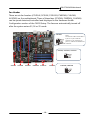
1
User’s Manual Sapphire Pure Black X58 PB-CI7S41X58 Intel X58/LGA1366 Series Mainboard TRADEMARK All products and company names are trademarks or registered trademarks of their respective holders. These specifications are subject to change without notice. Manual Revision 1.0 October 28, 2010 PB-CI7S41X58 Mainboard Federal Communications Commission (FCC) Statement This device has been tested and found to comply with the limits for a Class B digital device, pursuant to Part 15 of FCC Rules. These limits are designed to provide reasonable protection against harmful interference in a residential installation. This equipment generates, uses and can radiate radio frequency energy and, if not installed and used in accordance with instructions contained in this manual, may cause harmful interference to radio and television communications. However, there is no guarantee that interference will not occur in a particular installation. If this product does cause harmful interference to radio or television reception, which can be determined by turning the equipment off and on, the user is encouraged to try to correct the interference by one or more of the following measures: Reorient or relocate the receiving antenna. Increase the separation between the equipment and receiver. Connect the product into an outlet on a circuit different from that to which the receiver is connected. Consult the dealer or an experienced radio/TV technician for help. Note1: Connecting this device to peripheral devices that do not comply with Class B requirements, or using an unshielded peripheral data cable, could also result in harmful interference to radio or television reception Note2: The user is cautioned that any changes or modifications not expressly approved by the party responsible for compliance could void the user’s authority to operate this product. Note3: To ensure that the use of this product does not contribute to interference, it is necessary to use shielded I/O cables CE: Radiation of EN 55022 & Immunity of EN 55024 Waste Electrical and Electronic Equipment (WEEE) Statement To protect the global environment, this product must be sent to separate collection facilities for recovery and recycling. DISPOSAL Do not dispose of this product as unsorted municipal waste. Collect such waste separately for special treatment. ~i~ PB-CI7S41X58 Mainboard Table of Contents Chapter 1 Introduction ......................................................................... 1 1-1 Mainboard Specifications ........................................................................... 1 1-2 Package Contents ..................................................................................... 3 1-3 Mainboard Layout ...................................................................................... 4 I/O Back Panel .......................................................................................... 6 Chapter 2 Installation ........................................................................... 8 2-1 Before You Begin ....................................................................................... 8 2-2 Installing the I/O Shield .............................................................................. 8 2-3 Securing to the Chasis............................................................................... 8 2-4 Installing the CPU and Fan Heatsink .......................................................... 9 2-5 Installing System Memory ........................................................................ 10 Memory configurations: ........................................................................... 10 Memory Installation: .................................................................................11 2-6 Installing Expansion Cards ....................................................................... 12 PCI-E Slots ............................................................................................. 12 PCI Slot .................................................................................................. 13 2-7 Connecting Cables .................................................................................. 13 Connecting Power Supply Cables ............................................................ 13 Connecting IDE Cables ........................................................................... 14 Connecting Serial ATA (SATA) Cables ...................................................... 14 Connecting to the Internal Headers and Connectors ................................. 15 2-8 Diagnostics LED ...................................................................................... 19 2-9 LED Status Indicators .............................................................................. 19 2-10 Onboard Buttons ................................................................................... 20 Clear CMOS Button................................................................................. 20 Reset and Power Button .......................................................................... 20 2-11 Dual BIOS Switched Jumper .................................................................. 21 Chapter 3 Configuring the BIOS ........................................................ 22 ~ ii ~ PB-CI7S41X58 Mainboard 3-1 Enter BIOS Setup .................................................................................... 22 3-2 Main Menu .............................................................................................. 23 3-3 Performance Menu .................................................................................. 24 CPU Configuration .................................................................................. 26 Memory Timing Configuration .................................................................. 28 Voltage Configuration .............................................................................. 30 3-4 Advanced Menu....................................................................................... 32 IDE Configuration .................................................................................... 33 Hardware Health Configuration ................................................................ 34 USB Configuration .................................................................................. 35 ACPI Configuration.................................................................................. 36 Intel VT-d Configuration ........................................................................... 37 PCI Express Configuration....................................................................... 37 Onboard Device Configuration ................................................................. 39 3-5 PCIPnP Menu ......................................................................................... 40 3-6 Boot Menu............................................................................................... 41 Boot Settings Configuration ..................................................................... 41 3-7 Security Menu ......................................................................................... 43 3-8 Exit Menu ................................................................................................ 44 Chapter 4 Driver Installation .............................................................. 45 Chapter 5 AMI POST Code ................................................................. 47 ~ iii ~ PB-CI7S41X58 Mainboard Chapter 1 Introduction 1-1Mainboard Specifications CPU Supports Intel® Core i7 series processor in the LGA1366 package Chipset Intel® X58 and ICH10R chipset System Memory Six 240-pin DDR3 SDRAM DIMM sockets Supports 1.5v DDR3-1066/1333+ DIMMs with triple channel architecture Supports x16 and x8 DIMMs, non-ECC, unbuffered DIMMs Supports up to 24GB system memory USB Ports Ten USB 2.0 ports (eight at rear panel, two onboard by header), supporting transfer speeds up to 480Mbps Two USB 3.0 ports (at rear panel) backwardly compatible with USB 2.0 supporting transfer speeds up to 4.8Gbps Supports wake-up from S1 and S3 modes SATA Ports Six SATA2 ports including one eSATA port, with 3Gb/s data transfer rate, supporting RAID 0, RAID 1, RAID 10 and RAID 5 from Intel® ICH10R. Two SATA3 ports with6Gb/s data transfer rate, supporting RAID 0 and RAID 1 from Marvell® 88SE9128. Onboard LAN One Gigabit Ethernet from Marvell 88E8057 Gigabit controller Bluetooth Atheros AR3011 is a highly integrated, all-CMOS, single chip with Bluetooth® 2.1 + EDR supported ~1~ PB-CI7S41X58 Mainboard Onboard IEEE1394a (Firewire) Two IEEE1394a ports (one at rear panel, one onboard by header) with 400 Mbps transfer rate Onboard Audio Supports 8-channel High-Definition audio Supports rear panel SPDIF, Coaxial output Supports Jack-detection function Expansion Slots Four PCI-Express x16 connectors Supports ATI® CrossFireXTM Technology One PCI slot BIOS 8Mb SPI Flash with AMI based BIOS Supports ACPI (Advanced Configuration and Power Interface) Supports dual BIOS, switched by on board jumpers Form Factor ATX form factor of 305mm x 245 mm Operating systems: Support Windows XP, Windows Vista and Windows 7 (32 and 64 bit) ~2~ PB-CI7S41X58 Mainboard 1-2Package Contents Your Sapphire Pure Black X58 mainboard comes with the following accessories. 1. Mainboard 2. Quick Installation Guide 3. Driver CD 4. I/O Shield 5. SATA Data Cable *6 6. IDE Cable ~3~ PB-CI7S41X58 Mainboard 1-3Mainboard Layout The following figure shows the location of components on the mainboard. Page 5 for the Key ~4~ See PB-CI7S41X58 Mainboard Item Component description 1 CPU Socket 1366 2 Intel X58 Chipset 3 Intel ICH10R Chipset 4 DDR3 DIMM Slots 1-6 5 24-Pin ATX Power Connector 6 8-pin ATX_12V Power Connector 7 PCI-E x16 Slots1-4 8 PCI Slot 9 IDE Connector 10 SATA3 Connectors *2 11 SATA2 Connectors *5 12 Front Panel Header 13 USB Header 14 IEEE1394a Header 15 Power Button 16 Reset Button 17 Clear CMOS Button 18 PC Speaker 19 Debug LED Display 20 Mainboard Battery 21 Front Panel Audio Header 22 S/PDIF Header 23 CPU Fan Header 24 3-pin Fan Header *5 25 Back Panel Connectors (see next page for detail) ~5~ PB-CI7S41X58 Mainboard I/O Back Panel The I/O back panel for this mainboard is shown below. When installing the mainboard into the computer case, use the bundled I/O shield to protect this back panel. 1. PS/2 Keyboard/Mouse Port This connector is used for a keyboard or mouse. You can plug a PS/2 keyboard or mouse directly into this connector. 2. Coaxial S/PDIF-Out This SPDIF (Sony & Philips Digital Interconnect Format) connector is used for digital audio transmission to external speakers/amplifier through a coaxial cable. 3. Optical S/PDIF-Out This SPDIF (Sony & Philips Digital Interconnect Format) connector is used for digital audio transmission to external speakers/amplifier through an optical fiber cable. 4. Bluetooth Bluetooth wireless technology is an interface intended for wireless control/data communication 5. USB 2.0 Ports (Eight) The mainboard provides an OHCI (Open Host Controller Interface) Universal Serial Bus root for attaching USB devices such as a keyboard, mouse or other USB-compatible devices. Supports data transfer rates up to 480Mb/s. 6. USB 3.0 ports (two) USB 3.0 ports are backwardly compatible with USB 2.0 devices. Supports data transfer rates up to 4.8Gb/s (SuperSpeed). ~6~ PB-CI7S41X58 Mainboard 7. ESATA Port The ESATA (External SATA) port provides connection to ESATA hard drives. 8. IEE1394a (Firewire) Port The IEEE 1394 port provides connection to IEEE 1394 devices. 9. LAN Ports with LEDs The mainboard provides one standard RJ-45 jack for connecting to a Local Area Network (LAN). Two LEDs are built into the RJ-45 LAN connector. These LEDs indicate the status of the LAN. LED A B LED Color LED state Indicates Off LAN link is not established On LAN link is established Blinking LAN activity is occurring N/A Off 10 Mb/s data rate Green On 100 Mb/s data rate Yellow On 1000 Mb/s data rate Green 10. Audio Ports This mainboard provides 2, 6, or 8channel audio. It is easy to differentiate between the audio functions by referring to the color of the jacks. Ports 2 channel 6 channel 8 channel Blue Line-In Line-In Line-In Lime Line-Out Front Stereo-Out Front Stereo-Out Pink Min-In Min-In Min-In Orange -- Center/Subwoofer Center/Subwoofer Black -- Rear Stereo-Out Rear Stereo-Out Gray -- -- Side Stereo-Out ~7~ PB-CI7S41X58 Mainboard Chapter 2 Installation 2-1 Before You Begin Please take note of all precautions before you install anything on to the mainboard or change any of the mainboard settings. Turn off the power to your system and discharge your body’s static electric charge by touching a grounded surface—for example, the metal surface of the power supply—before performing any hardware procedure. The manufacturer assumes no liability for any damage, caused directly or indirectly, by improper installation of any components by unauthorized service personnel. If you do not feel comfortable performing the installation, consult a qualified computer technician. Damage to system components, the mainboard , and injury to you may result if power is applied during installation. 2-2 Installing the I/O Shield The mainboard comes complete with an I/O shield. When installed in the chassis, the shield blocks radio frequency transmissions, protects internal components from dust and foreign objects, and promotes correct airflow within the chassis. Install the I/O shield before installing the mainboard in the chassis. Place the shield inside the chassis. Press the shield into place so that it fits tightly and securely. If the shield does not fit, obtain a properly sized shield from the chassis supplier. 2-3 Securing to the Chassis When installing the mainboard, you have to secure the mainboard into the chassis by fastening with nine screws. Please refer to your chassis manual for instructions on installing. ~8~ PB-CI7S41X58 Mainboard 2-4 Installing the CPU and Fan Heatsink To install the CPU :1. Open the socket lever by pushing the lever down and away from the socket. Remove the protective socket cover from the socket. Do not touch the socket contacts. 1 Note: Do not discard the protective socket cover. Be sure toalways replace the cover unless the CPU is installed. 2. Align the CPU notches to the socket protrusions. Place CPU straight down without tilting or sliding it. 3. Close the load plate and engage the socket lever. 4. To install fan heatsink, align the holes on the mainboard. Press the four hooks down to fasten the cooler. You will hear a “click” upon full engagement. Gently rotate the cap clockwise 1/4 turn to fasten the heatsink onto the mainboard 5. 2 3 4 Connect the 4-wire fan cable to the 4-pin CPUFAN header on the mainboard. 5 - ~9~ PB-CI7S41X58 Mainboard 2-5 Installing System Memory This mainboard has six 240-pin DIMM sockets for DDR3 memory. These slots support 1GB, 2GB and 4GB DDR3 DIMMs. Make sure that you install memory modules of the same type and density in different channel DIMM slots for Triple-Channel/Dual-Channel mode. There must be at least one memory bank populated to ensure normal operation and always inset the memory module into the DIMM slot 1 first. Memory configurations: Use the following the recommendations for installing memory. 1 DIMM (Single-Channel): install into DIMM slot 1. 2 DIMMs (Dual-Channel): install into DIMM slots 1 and 3. 3 DIMMs (Triple-Channel): install into DIMM slots 1, 3 and 5. 4 DIMMs (Triple-Channel): install into DIMM slots 1, 3, 5and 2. 5 DIMMs (Triple-Channel): install into DIMM slots 1, 3, 5, 2 and 4. 6 DIMMs (Triple-Channel): install into DIMM slots 1, 3, 5, 2, 4 and 6. DIMM Qty 1 DIMM 2 DIMMs (Single Channel) (Dual Channel) DIMM#2 -- -- -- V V V DIMM#1 V V V V V V DIMM#4 -- -- -- -- V V DIMM#3 -- V V V V V DIMM#6 -- -- -- -- -- V DIMM#5 -- -- V V V V Location 3 DIMMs 4 DIMMs 5 DIMMs 6 DIMMs (Triple Channel) (Triple Channel) (Triple Channel) (Triple Channel) DIMM#2 DIMM#1 DIMM#4 DIMM#3 DIMM#6 DIMM#5 ~ 10 ~ PB-CI7S41X58 Mainboard Memory Installation: DDR3 and DDR2 memory modules are physically different. Please only install DDR3 DIMMs in this mainboard. To make sure you have the correct DIMM, check that all the notches line up with the DDR3 DIMM slot. To install the DIMM, follow these steps: 1. Pull both clips on either side of the slot outwards. Align the DIMM module with the slot. 2. Press straight down until the plastic clips close and the module fits tightly into the DIMM slot. ~ 11 ~ PB-CI7S41X58 Mainboard 2-6 Installing Expansion Cards The mainboard provides four PCI Express 2.0 x16 slots and one PCI slot. PCIE1_X16 PCI-E2.0 x16 slot (with x16 link, Blue) PCIE2_X8 PCI-E2.0 x16 slot (with x8 link, Blue) PCI slot (Black) PCIE3_X8 PCI-E2.0 x16 slot (with x8 link, Blue) PCIE4_X4 PCI-E1.0 x16 slot (with x4 link, Gray) PCI-E Slots The design of this motherboard supports ATI CrossFireXTM multiple graphic card technology. Please refer to the location of slots and recommended configuration table for PCI-E operating mode to get the best performance possible. Recommended configuration table Slot location VGA card PCIE1_x16 (Blue) PCIE2_x8 (Blue) 1 VGA card x16 2 VGA cards x16 x8 3 VGA cards x16 x8 PCIE3_x8 (Blue) x8 To install a PCI Express card: 1. 2. Place the card in an available PCI Express slot and press down on the card until it is completely seated in the slot. If the card is not seated properly, it could cause a short across the pins. Secure the card’s metal bracket to the chassis back panel with a screw. ~ 12 ~ PB-CI7S41X58 Mainboard PCI Slot The one PCI slot provided supports a variety of expansion cards such as a LAN card, USB card, SCSI card and other cards that comply with PCI specifications. When installing a card into the PCI slot, be sure that it is fully seated. Secure the card’s metal bracket to the chassis back panel. 2-7 Connecting Cables This section takes you through all the necessary connections on the mainboard. Connecting Power Supply Cables 24-pin ATX Power PW1 is the main power supply connector. Make sure that the power supply cable and pins are properly aligned with the connector on the mainboard. Firmly plug the power supply cable into the connector and make sure it is secure. Note: If you’d like to use the 20-pin ATX power supply, please plug in your power supply cable aligned with pins 1 & 13. The 24-pin main power connector is backwardly compatible with ATX power supplies with 20-pin connectors. 8-pin ATX 12V Power PW2, the 8-pin ATX 12V power connector, is used to provide power to the CPU. Align the power plug to the connector and press firmly until seated. 24-pin ATX Power connector 8-pin ATX Power connector ~ 13 ~ PB-CI7S41X58 Mainboard Connecting IDE Cables The IDE connector supports Ultra ATA 133/100 IDE hard/optical disk drives. 1. Connect one end of the cable (single connector) to the mainboard. 2. Connect another connector on the cable to the Ultra ATA master device. 3. Connect the other connector to a slave device Note: If you install two hard/optical disk drives, you must configure the second drive as a slave device by setting its jumper accordingly. Refer to the disk drive documentation for the jumper settings. IDE connector Connecting Serial ATA (SATA) Cables SATA cables support the Serial ATA protocol. Each cable can be used to connect one internal SATA drive to mainboard. The SATA2 0~SATA2 4 connectors are controlled by the South Bridge Chipset and operate at a speed up to 3Gb/s. The SATA3 0 and SATA3 1 connectors are SATA3 ports in red color and operate from the Marvell 9128 chipset at a transfer rate up to 6Gb/s. SATA4 Attach one end of the SATA cable to one of the SATA connectors on the board and attach the other end of the cable to the SATA drive SATA 2 (bottom) SATA 3 (top) SATA3 0 (bottom) SATA3 1 (top) SATA 0 (bottom) SATA 1 (top) ~ 14 ~ PB-CI7S41X58 Mainboard Connecting to the Internal Headers and Connectors Front Panel Header The front panel header on this motherboard is one connector used to connect the front panel switches and LEDs. PWR_LED Attach the front panel power LED cable to these two pins of the connector. The Power LED indicates the system’s status. System Status On Off S1 S3 S4 Power LED indicates The LED is on The LED is off The LED is on The LED will blink The LED is off PW_ON Attach the power button cable from the case to these two pins. Pressing the power button on the front panel turns the system on and off rather than using the onboard button. HD_LED Attach the hard disk drive indicator LED cable to these two pins. The HDD indicator LED indicates the activity status of the hard disks. RESET Attach the Reset switch cable from the front panel of the case to these two pins. The system restarts when the RESET switch is pressed. Header Signal 1 HD_PWR 3 HD Active 2 PWR LED+ 4 PWR LED- 5 Ground 7 RST BTN 6 PWR BTN 8 Ground No Connect 9 +5V Empty 10 Empty HD_LED PWRLED RESET PWRSW ~ 15 ~ Pin PB-CI7S41X58 Mainboard USB Header This mainboard contains eight (8) USB 2.0 ports that are exposed on the rear panel of the chassis. This mainboard also contains one 10-pin internal header connectors onboard that can be used to connect an optional external bracket containing two (2) USB 2.0 ports. Refer to the following steps: 1. Secure the bracket to either the front or rear panel of your chassis (not all chassis are equipped with the front panel option). 2. Connect the cable(s) to the USB 2.0header on the mainboard. 1 2 V CC US B 0- US B 1- US B 0+ US B 1+ Ground E mpt y Note: Ground No Connec t Please do not connect a 1394 cable to USB connector, which will cause damage to the mainboard. 1394 Header This header is used for IEEE1394 devices. There is a header cap on the 1394 header to prevent confusion with the USB header. If you do not require the additional external 1394 connections, you do not need to install them. Refer to following steps: 1. Secure the bracket to either the front or rear panel of the system case (not all system cases are equipped with the front panel option). 2. Remove the header cap of 1394 3. Connect the end of the cable to the IEEE1394a headers on the mainboard. ~ 16 ~ PB-CI7S41X58 Mainboard CFPA Header This header allows you to connect the front panel audio. The audio connector supports HD audio standard. S/PDIF Header This header is used to connect S/PDIF (Sony & Philips Digital Interconnect Format) interface for digital audio transmission. ~ 17 ~ PB-CI7S41X58 Mainboard Fan Header There are six fan headers (CPUFAN, SYSFAN, SYSFAN1, PWRFAN, CHAFAN, AUXFAN) on the motherboard. Three of these fans (CPUFAN, PWRFAN, CHAFAN) can be speed detected/controlled and displayed in the Hardware Health Configuration section of the CMOS Setup. The fans are automatically turned off after the system enters S3, S4 or S5 mode. CPUFAN Note: The CPU fan cable can be either a 3-pin or a 4-pin connector. Connect a 3-pin connector to pins 1, 2, and 3on the mainboard connector. SYSFAN, SYSFAN1, AUXFAN SYSFAN CHAFAN AUXFAN PWRFAN SYSFAN1 ~ 18 ~ CPUFAN CHAFAN, PWRFAN PB-CI7S41X58 Mainboard 2-8 Diagnostics LED This mainboard provides a two-digit POST code to show why the system may be failing to boot. It is useful during a troubleshooting situation. This Debug LED will also display the current CPU temperature after the system has fully booted into the operating system. Debug LED 2-9 LED Status Indicators This mainboard provides three LEDs to indicate the system’s status. POWER LED (LED3, Green): When the System is powered on: This LED is on. STANDBY LED (LED4, Blue): When the System is in Standby Mode: This LED is on. This LED will remain on as long as the motherboard is receiving constant power. DIMM LED (LED2, Yellow): When the Memory slot is functional: This LED is on. POWER LED STANDBY LED DIMM LED ~ 19 ~ PB-CI7S41X58 Mainboard 2-10 Onboard Buttons These onboard buttons include Clear CMOS, RESET and POWER, which allow you to easily clear the CMOS, reset the system and turn on/off the system. Clear CMOS Button The mainboard uses the CMOS RAM to store some of the system configuration. The CMOS can be cleared by pressing the Clear CMOS button. Reset and Power Button These onboard buttons allow you to easily turn on/off the system and allow for easy debugging and testing of the system during troubleshooting situations. The Reset button with LED indicates the activity status of the hard disk drives and will blink accordingly. The Power button with LED indicates the system’s status. When the system is powered on, the LED blinks red. Clear CMOS Button Reset Button ~ 20 ~ Power Button PB-CI7S41X58 Mainboard 2-11 Dual BIOS Switched Jumper This mainboard includes two onboard BIOS, (Primary and Secondary BIOS), to support the Dual BIOS functionality which is set by on board jumper. When the primary BIOS is corrupted or failed, you can use the secondary BIOS to take over on the next system boot to ensure normal system operation. To enable the secondary BIOS, please refer to the following steps: 1. Turn off the system power. 2. Change the BIOS Select jumper from “P” to “S” position. 3. Turn on the system power. Secondary BIOS Primary BIOS BIOS Select Jumper (When the Secondary BIOS is functional, the LED indicator is on.) ~ 21 ~ PB-CI7S41X58 Mainboard Chapter 3 Configuring the BIOS This chapter provides information on the BIOS Setup program and allows you to configure the system for optimum use. 3-1 Enter BIOS Setup The BIOS is the communication bridge between hardware and software. Correctly setting the BIOS parameters is critical to maintain optimal system performance. Use the following procedure to change BIOS settings. 1. Power on the computer. 2. Press the Del key when the following message briefly shows upon the bottom of the display during Power On Self Test (POST). Press F1 to continue, DEL to enter Setup. Pressing Del takes you to the BIOS CMOS Setup Utility. Note1: It is strongly recommended that you do not change the default BIOS settings. Changing some settings could damage your computer. Note2: The BIOS options in this manual are for reference only. BIOS screens in manuals are usually the first BIOS version when the board is released and may be different from your purchased motherboard. Users are welcome to download the latest BIOS version from our official website Control Keys Please check the following table for the function description of each Control key. Control Key(s) / / +/<Enter> Function Description Moves cursor left or right to select Screens Moves cursor up or down to select items To change option for the selected items To bring up the selected screen <F1> <F9> <F10> To display the General Help Screen To load optimal default values for all the settings To save changes and exit the BIOS SETUP UTILITY <ESC> To jump to the Exit Screen or exit the current screen ~ 22 ~ PB-CI7S41X58 Mainboard 3-2 Main Menu When entering the BIOS SETUP UTILITY, the main menu screen appears. This main menu includes the system overview and displays the basic system configuration, such as BIOS ID, CPU name, memory size and system date/time. BIOS SETUP Main Performance AdvancedUTILITY PCIPnP System Overview Exit Use [+] or [-] to Configure system Time. X5680 @3.33GHz Select Screen Select Item + - Change Option System Memory Size :6136MB System Time System Date Security Use [Enter], [TAB] Or [SHIFT-TAB] to Select a field. AMI BIOS Version :08.00.16 Build Date :10/12/10 ID :1AEGHA13 Processor Intel(R) Xeon(R) CPU Speed :3333MHz Count :1 Boot [13:55:02] [Tue 10/12/2010] F1 General Help F10 Save and Exit ESC Exit v02.69 (C) Copyright 1985-2010, American Megatrends, Inc. (( AMI BIOS This item displays the current BIOS version, build date and ID information. Processor Current CPU name and speed information. System Memory Displays current system memory size. System Time Allows you to set the system time. The time format is <hour>:<minute>:<second>. System Date Allows you to set the system date. The format is <Day><Month><Date><Year>. [Day] Weekday from Sun. to Sat., this is automatically displayed by BIOS. [Month] The month from 1 to 12. [Date] The date from 1 to 31 can be keyed by numeric function keys. [Year] The year can be adjusted by users. ~ 23 ~ PB-CI7S41X58 Mainboard 3-3 Performance Menu The Performance menu is used to configure the frequency and voltage for CPU and memory. BIOS SETUP AdvancedUTILITY PCIPnP Main Performanc e Frequency & Voltage Configuration Boot Security Exit Configure CPU. Manufacturer: Intel Intel (R) Xeon (R) CPU X5680 @ 3.33GHz Ratio Status: Unlocked (Min:12, Max:25) Ratio Actual Value: 25 Current QPI frequency :6.400GT Current Memory frequency :1066 MHz CPU Configuration Memory Timing Configuration Voltage Configuration CPU Frequency Setting PCIE Frequency Setting CPU Ratio QPI Frequency Memory Frequency Memory Timing CPU Uncore Frequency (Mhz) [Auto] [100] [25] [Auto] [Auto] [Auto] [Auto] Load Profiles Save Profiles [Press Enter] [Press Enter] Select Screen Select Item + - Change Option F1 General Help F10 Save and Exit ESC Exit v02.69 (C) Copyright 1985-2010, American Megatrends, Inc. (( CPU Frequency Setting Allows you to select the CPU Frequency. The default is 0 by auto detection. PCIE Frequency Setting Allows you to select the PCIE Frequency. The default is 0 by auto detection. CPU Ratio Allows you to select the CPU Clock Ratio. Multiply CPU clock with this ratio, you can get the CPU speed. If the multiplier is locked, this option will be unavailable. QPI Frequency Allows you to select the QPI Frequency. Options: Auto, 4.800GT, 5.866GT, 6.400GT Memory Frequency Allows you to select the Memory Frequency. Options: Auto, Force DDR-800, Force DDR-1066, Force DDR-1333. ~ 24 ~ PB-CI7S41X58 Mainboard Memory Timing Allows you to select the Memory Timing. Options: Auto, By DRAM Ratio, By DDR-800, By DDR-1067, By DDR-1333, By DDR-1600, By DDR-1867. CPU Uncore Frequency (Mhz) Allows you to select the CPU Uncore Frequency, the Uncore clock must be at least 2x DRAM clock for overclocking. Load Profiles Allows you to load the BIOS settings saved in the BIOS Flash. Press <Enter> to load the file. Options: Profile 1, Profile 2, Profile 3, Profile 4. Save Profiles Allows you to save the current BIOS file to the BIOS Flash. Press <Enter> to choose a profile number to save your BIOS settings. Options: Profile 1, Profile 2, Profile 3, Profile 4. ~ 25 ~ PB-CI7S41X58 Mainboard CPU Configuration Main BIOS SETUP UTILITY PCIPnP Advanced Performance e Configure advanced CPU settings Module version: 01.0C C1E Support Security Exit Configure CPU. CPU Revision :B1 Manufacturer: Intel Intel (R) Xeon (R) CPU X5680 @ 3.33GHz Frequency :3.33GHz BCLK Speed :133MHz Cache L2 :384 KB Cache L2 :1536 KB Cache L3 :12288 KB Ratio Status: Unlocked (Min:12, Max:25) Ratio Actual Value: 25 C1E Support Max CPUID Value Limit Intel (R) Virtualization Tech Execute-Disable Bit Capability Intel (R)HT Technology Active Processor Cores A20M Intel (R)SpeedStep (TM) tech Intel (R)TurboMode tech Performance/Watt select Intel (R)C-STATE tech C3 State C6 State C State package limit setting C1 Auto Demotion C3 Auto Demotion Boot [Enabled] [Disabled] [Disabled] [Enabled] [Enabled] [All] [Disabled] [Enabled] [Enabled] [Traditional] [Enabled] [ACPI P2] [Enabled] [Auto] [Enabled] [Enabled] Select Screen Select Item +- Change Option F1 General Help F10 Save and Exit ESC Exit v02.69 (C) Copyright 1985-2010, American Megatrends, Inc.( ( Allows you to select the lowest C state Enhanced supported. Options: Enabled, Disabled Max CPUID Value Limit We recommend leaving it disabled, unless you are using a very old OS or experiencing problems related to CPU identification/compatibility. Options: Enabled, Disabled. Intel (R) Virtualization Tech When this function is enabled, it allows a VMM (Virtual Machine Monitor) to utilize the additional hardware capabilities provided by Intel Virtualization Technology. Options: Enabled, Disabled. ~ 26 ~ PB-CI7S41X58 Mainboard Execute-Disable Bit Capability When this function is disabled, it forces the XD feature flag to always return to zero (0). Options: Enabled, Disabled. Intel (R) HT Technology Allows you to enable the Intel® HT (Hyper-Threading) Technology. Options: Enabled, Disabled. Active Processor Cores This item is the number of cores to enable in each processor package. The Options: All, 1 and 2. A20M This item may need to be enabled for Legacy OS and Applications. Options: Enabled, Disabled. Intel (R) SpeedStep™ tech Enables the Intel® SpeedStep technology (EIST). Options: Enabled, Disabled. Intel (R) TurboMode tech Enables the Intel® Turbo Mode technology. Turbo mode allows processor cores to run faster than marked frequency in specific condition. Options: Enabled, Disabled Performance/Watt select Automated energy efficiency that scales energy usage to the workload to achieve optimal performance/watt. Intel (R) C-STATE tech Enables the Intel® C-STATE technology, allowing the CPU to save more power under idle mode. Options: Enabled, Disabled. C3 State Allows you to select C3 State for Nehalem processor. Options: ACPI C2,ACPI C3, Disabled. C6 State Allows you to select C6 State for Nehalem processor. Options: Enabled, Disabled. C State package limit setting We recommend that you set this item to Auto for BIOS to automatically detect the C-State mode supported by your CPU. Options: Auto, C1, C3, C6, C7. ~ 27 ~ PB-CI7S41X58 Mainboard C1 Auto Demotion When enabled, CPU will conditionally demote C3/C6/C7 requests to C1 based on uncore auto-demote information. Options: Enabled, Disabled C3 Auto Demotion When enabled, CPU will conditionally demote C6/C7 requests to C3 based on uncore auto-demote information. Options: Enabled, Disabled Memory Timing Configuration BIOS SETUP UTILITY PCIPnP Main Advanced Performanc e Memory Timing Configuration tCL tRCD tRP tRAS tRFC Command Rate tWR tWTR tRRD tRTP tFAW Back-to-Back CAS Delay CHA Round Trip Latency CHB Round Trip Latency CHC Round Trip Latency tCL [New / Current] [Auto (9) ] [Auto (9) ] [Auto (9) ] [Auto (24) ] [Auto (74) ] [Auto (1) ] [Auto (10) ] [Auto (5) ] [Auto (4) ] [Auto (5) ] [Auto (20) ] [Auto (0) ] [Auto (57) ] [Auto (59) ] [Auto (60) ] Boot Security Exit Minimum CAS Latency Time. 0 by Auto detection Min=6, Max=15 Select Screen Select Item +- Change Option F1 General Help F10 Save and Exit ESC Exit v02.69 (C) Copyright 1985-2010, American Megatrends, Inc.( ( Set the CAS latency time. Options: 6 ~ 15, 0 by auto detection. tRCD Set the RAS to CAS Delay time for Read/Write commands to the same bank. Options: 3 ~ 15, 0 by auto detection. tRP Set the Row Precharge time. This is the Precharge-to-Active or Auto-to-Refresh of the same bank. Options: 3 ~ 15, 0 by auto detection. ~ 28 ~ PB-CI7S41X58 Mainboard tRAS Set the minimum RAS# active time. Options: 9 ~ 63, 0 by auto detection. tRFC Set the minimum refresh recovery time. Options: 15 ~ 255, 0 by auto detection. Command Rate Set the command timing setting on a per clock unit basis. Options: Auto, 1 and 2, 0 by auto detection. tWR Set the tWR values. Options: 3 ~ 11, 0 by auto detection. tWTR Set the tWTRvalues Options: 4 ~ 31, 0 by auto detection. tRRD Set the tRRDvalues Options: 4 ~ 15, 0 by auto detection. tRTP Set the tRTPvalues. Options: 4 ~ 15, 0 by auto detection. tFAW Set the tFAWvalues Options: 15 ~ 63, 0 by auto detection. Back-to-Back CAS Delay Set Back-to-Back CAS values. Options: 3 ~ 31, 0 by auto detection. CHA/ CHB/ CHC Round Trip Latency Set Round Trip Latency values. Options: 1 ~ 255, 0 by auto detection. ~ 29 ~ PB-CI7S41X58 Mainboard VoltageConfiguration Main Performanc e Voltage Configuration BIOS SETUP UTILITY PCIPnP Advanced Loadline Control CPU Thermal Current CPU VCore CPU VCore Current DIMM Voltage DIMM Voltage Current VTT CPU VTT Current IOH VCore IOH VCore Current QPI PLL QPI PLL Current IOH/ICH IO Voltage IOH/ICH IO Voltage Current CPU PLL VCore CPU PLL VCore Current ICH VCore ICH VCore DIMM DQ Vref [Enabled 100%] [Enabled] 1.18750V [Auto] 1.50V [Auto] 1.100V [Auto] 1.100V [Auto] 1.100V [Auto] 1.100V [Auto] 1.800V [Auto] 1.800V 1.800V 550mV : : : : : : : : : : : : : : : : : CPU PWM Frequency DDR PWM Frequency VTT PWM Frequency : [460KMz] : [250KMz] : [250KMz] Boot Security Exit Enabled Disabled Select Screen Select Item +- Change Option F1 General Help F10 Save and Exit ESC Eit v02.69 (C) Copyright 1985-2010, American Megatrends, Inc.( ( Loadline Control Loadline Control function is a safety measure to protect the CPU. Enable 100%: To project CPU from over voltage while overloading of current, Disable: Allow CPU to overvoltage for large current loading, Enabled 50%: For balanced performance and protection. CPU Thermal Allows you to control the CPU thermal. Options: Enabled, Disabled. Current CPU VCore Displays the current CPU VCorevoltage. CPU VCore Allows you to adjust the CPU Vcore voltage. Options available depend on CPU. We recommend that you select [Auto] asthe default value. Current DIMM Voltage Displays the current DIMMvoltage. ~ 30 ~ PB-CI7S41X58 Mainboard DIMM Voltage Allows you to adjust the DIMM Slot voltage. Options: 1.10V ~1.50V in 0.05V increments and 1.50V ~ 2.50V in 0.01V increments. Current VTT Displays the current VTTvoltage. CPU VTT Allows you to adjust the CPU VTT voltage. Options: 1.100V ~1.450V in 0.025V increments. Current IOH VCore Displays the current Intel IOH chip voltage. IOH VCore Allows you to adjust the IOH chip voltage. Options: 1.100V ~1.240V in 0.01V increments. Current QPI PLL Displays the current QPI PLL voltage. QPI PLL Allows you to adjust the QPI PLL voltage. Options: 1.100V ~1.450V in 0.025V increments. Current IOH/ICH IO Voltage Displays the current the Intel IOH/ICH chip I/O voltage. IOH/ICH IO Voltage Allows you to adjust the Intel IOH/ICH chip I/O voltage. Options: 1.100V ~1.240V in 0.01V increments. Current CPU PLL VCore Displays the current CPU PLL voltage. CPU PLL VCore Allows you to adjust the CPU PLL voltage. Options: 1.800V ~2.150V in 0.025V increments. Current ICH VCore Displays the current Intel ICH chip voltage. ICH VCore Allows you to adjust the Intel ICH chip voltage. Options: 1.050V ~1.400V in 0.025V increments. ~ 31 ~ PB-CI7S41X58 Mainboard DIMM DQ Vref Allows you to adjust the DIMM DQ reference voltage. DQ Vref= DIMM voltage+Offset Options: +480mV ~-490mV in 10mV increments CPU PWM Frequency Allows you to adjust the CPU PWM Frequency Options: 380KHz, 460KHz, 520KHz, 580KHz, 770KHz, 870KHz, 950KHz, 1010KHz. DDR PWM Frequency Allows you to adjust the DDR PWM Frequency Options:250KHz, 500KHz. VTT PWM Frequency Allows you to adjust the VTT PWM Frequency Options:250KHz, 500KHz. 3-4 Advanced Menu This main menu is to set up onboard peripherals such as IDE, RAID, USB, LAN, and MAC control and to monitor the real-time system status of your PC, including temperature, voltages, and fan speed. Main Performance BIOS SETUP PCIPnP Advanced UTILITY Advanced Settings WARNING: Setting wrong values in below sections may cause system to malfunction. IDE Configuration Hardware Health Configuration USB Configuration ACPI Configuration Intel VT-d Configuration PCI Express Configuration Onboard device Configuration Boot Security Exit Configure the IDE device(s). Select Screen Select Item +- Change Option F1 General Help F10 Save and Exit ESC Exit v02.69 (C) Copyright 1985-2010, American Megatrends, Inc.( ( ~ 32 ~ PB-CI7S41X58 Mainboard IDE Configuration BIOS SETUP AdvancedUTILITY IDE Configuration SATA#1 Configuration Configure SATA#1 as SATA#2 Configuration Primary IDE Master Primary IDE Slave Secondary IDE Master Secondary IDE Slave Third IDE Master Fourth IDE Master IDE Detect Time Out (sec) [Compatible] [IDE] [Enhanced] : : : : : : [Hard Disk] [ATAPI CDROM] [Not Detected] [Not Detected] [Not Detected] [Not Detected] Disabled Compatible Enhanced Select Screen Select Item +- Change Option F1 General Help F10 Save and Exit ESC Exit [35] AHCI Configuration v02.69 (C) Copyright 1985-2010, American Megatrends, Inc.( ( SATA#1 Configuration Allows you to set the SATA#1 configuration. Options: Disabled, Compatible, Enhanced. Configure SATA#1 as Allows you to set the onboard Serial SATA mode. This item appears only when you set the“SATA#1 Configuration” to Compatible or Enhanced. IDE: Use the SATA hard disk drivers as Parallel ATA storage devices. RAID: Create a RAID 0, 1, 0+1, 5 configuration AHCI: Use the AHCI (Advanced Host Controller Interface) to enable advanced SATA features for improved performance with NCQ and Hot-plug features Note: To hot plug ESATA port on the rear panel, you will need to change 2 items in BIOS settings, please refer to the instructions below: 1. Set the “Configure SATA#1 as” item from “IDE” to “AHCI” setting. 2. The “Hot Plug” item appears, select “Enabled”. SATA#2Configuration Allows you set the SATA#2 Configuration. Options: Disabled, Enhanced. ~ 33 ~ PB-CI7S41X58 Mainboard Primary IDE Master/Primary IDE Slave/Secondary IDE Master/Secondary IDE Slave /Third IDE Master/Fourth IDE Master Sets the IDE configuration for the device that you specify. IDE Detect Time Out (sec) Selects the time out value for detecting IDE devices. Options: 0, 5, 10, 15, 20, 25, 30, 35. AHCI Configuration Allows you set the AHCI Configuration. Hardware Health Configuration BIOS SETUP AdvancedUTILITY Hardware Health Configuration H/W Health Function [Enabled] CPU VREG System : 40oC/104oF : 44oC/114oF : 34oC/93oF CPU Fan Speed Power Fan Speed Chassis Fan Speed : 2029 RPM : 1500 RPM : 2029 RPM VCore VDimm VTT NB +5V +12V VCC3 3VSB VBAT CPU Fan Type CPU Fan Mode Setting Temperature Limit of Highest Temperature Limit of Lowest Fan Highest setting Fan Lowest setting Power Fan Mode Setting Temperature Limit of Highest Temperature Limit of Lowest Fan Highest setting Fan Lowest setting Chassis Fan Mode Setting Temperature Limit of Highest Temperature Limit of Lowest Fan Highest setting Fan Lowest setting : 1.164 V : 1.505 V : 1.259 V : 1.111 V : 5.045 V : 12.320 V : 3.312 V : 3.360 V : 3.216 V [PWM FAN (4 pin)] [SmartFan] [050] [020] [100] [050] [SmartFan] [050] [020] [100] [050] [SmartFan] [050] [020] [100] [050] Enables Hardware Health Monitoring Device. Select Screen Select Item +- Change Option F1 General Help F10 Save and Exit ESC Exit v02.69 (C) Copyright 1985-2010, American Megatrends, Inc.( ( ~ 34 ~ PB-CI7S41X58 Mainboard H/W Health Function Enables the onboard hardware monitor to automatically detect and display the CPU and mainboard temperatures. Options: Enabled, Disabled. CPU / VREG / System Displays the current CPU, onboard regulator and system temperature. CPU /Power /Chassis Fan Speed Displays the current CPU, Power and Chassis Fan Speed VCore/VDimm/VTT/NB/+5V/+12V/VCC3/VBAT The current voltages are automatically detected and displayed by the system. CPU Fan Type Allows you to select the CPU Fan type. Options: PWM FAN (4 pin), PWM FAN (3 pin) CPU Fan Mode Setting This item controls the speed of the various fans on the motherboard. Choose [SmartFan] when you want the speed of the fans automatically controlled based on temperature. To set the fan speed to a constant rate, select [Manual] and then enter the speed from 0% to 100%. Set the desired speed for the Power and Chassis fans from 0% to 100%. The system defaults to 100%. USB Configuration BIOS SETUP AdvancedUTILITY USB Configuration Disabled Enabled Module Version – 2.24.5 – 13.4 USB Devices Enabled : None USB Functions Legacy USB Support USB 2.0 Controller Mode [Enabled] [Enabled] [HiSpeed] Select Screen Select Item +- Change Option F1 General Help F10 Save and Exit ESC Exit v02.69 (C) Copyright 1985-2010, American Megatrends, Inc.( ( ~ 35 ~ PB-CI7S41X58 Mainboard USB Functions Enables the USB controller. Options: Enabled, Disabled. Legacy USB Support Allows you select legacy support for USB devices. Options: Enabled, Disabled, Auto. USB 2.0 Controller Mode Allows you to configure the USB 2.0 Controller Mode. Options: HiSpeed (480Mbps), FullSpeed (12Mbps) ACPI Configuration BIOS SETUP AdvancedUTILITY ACPI Settings Suspend mode Repost Video on S3 Resume ACPI Version Features USB Device Wakeup From S3 High Precision Event Timer Select the ACPI state used for System Suspend. [Auto] [No] [ACPI v1.0] [Disabled] [Disabled] Select Screen Select Item +- Change Option F1 General Help F10 Save and Exit ESC Exit Suspend mode v02.69 (C) Copyright 1985-2010, American Megatrends, Inc.( ( Selects the ACPI state used to suspend system. Options: S1(POS), S3(STR), Auto. Repost Video on S3 Resume This item determines whether to invoke VGA BIOS POST on S3/STR resume. Options: No, Yes. ACPI Version Features Selects the ACPI version. Enable RDSP pointers to 64-bit fixed system description tables. Options: ACPI v1.0, ACPI v2.0, ACPI v3.0. ~ 36 ~ PB-CI7S41X58 Mainboard USB Device Wakeup From S3 Allows a USB keyboard device to wake-up the system from S3 state. Options: Enabled, Disabled. High Precision Event Timer Allows you to enable or disable the High Precision Event Timer. Options: Enabled, Disabled. Intel VT-d Configuration BIOS SETUP AdvancedUTILITY Intel VT-d Configuration Intel VT-d Disabled Enabled [Disabled] Select Screen Select Item +- Change Option F1 General Help F10 Save and Exit ESC Exit Intel VT-d v02.69 (C) Copyright 1985-2010, American Megatrends, Inc.( ( Allows you enable or disable the Intel Virtualization Technology for directed I/O. Options: Enabled, Disabled. PCI Express Configuration BIOS SETUP AdvancedUTILITY PCI Express Configuration Relaxed Ordering Maximum Payload Size Extended Tag Field No Snoop Maximum Read Request Size Active State Power Management Extended Synch [Auto] [Auto] [Auto] [Auto] [Auto] [Auto] [Disabled] Enables/Disables PCI Express Device Relaxed Ordering. Select Screen Select Item +- Change Option F1 General Help F10 Save and Exit ESC Exit v02.69 (C) Copyright 1985-2010, American Megatrends, Inc.( ( ~ 37 ~ PB-CI7S41X58 Mainboard Relaxed Ordering Enables the PCI Express device Relaxed Ordering. Options: Auto, Enabled, Disabled. Maximum Payload Size Sets the Maximum Payload size of PCI Express Device or allows the System BIOS to select the value. Options: Auto, 128 Bytes, 256 Bytes, 512 Bytes, 1024 Bytes, 2048 Bytes, 4096 Bytes. Extended Tag Field Allows device to use 8-bit TAG field as a requester. Options: Auto, Enabled, Disabled. No Snoop Enables the No Snoop function of PCI Express device. Options: Auto, Enabled, Disabled. Maximum Read Request Size Sets the Maximum Read Request size of PCI Express Device or allows System BIOS to select the value. Options: Auto, 128 Bytes, 256 Bytes, 512 Bytes, 1024 Bytes, 2048 Bytes, 4096 Bytes. Active State Power Management Enables PCI Express L0 and L1 link power states. Options: Enabled, Disabled. Extended Synch Allows generation of Extended Synchronization patterns. Options: Auto, Enabled, Disabled. ~ 38 ~ PB-CI7S41X58 Mainboard OnboardDevice Configuration BIOS SETUP AdvancedUTILITY Onboard Device Settings SATA 3.0 Storage Controller USB 3.0 Controller IEEE1394 Controller HD Audio Controller Marvell 88E8057 Giga LAN Giga Lan PXE Boot ROM C80P Show CPU Temperature [Enabled] [Enabled] [Enabled] [Enabled] [Auto] [Disabled] [Enabled] Restore on AC Power Loss [Power Off] Enables/Disables PCI Express Device Relaxed Ordering. Select Screen Select Item +- Change Option F1 General Help F10 Save and Exit ESC Exit v02.69 (C) Copyright 1985-2010, American Megatrends, Inc.( ( SATA 3.0 Storage Controller Enables the onboard SATA 3.0 Storage controller. Options: Enabled, Disabled. USB 3.0 Controller Enables the onboard USB 3.0 controller. Options: Enabled, Disabled. IEEE1394 Controller Enables the onboard IEEE1394 controller. Options: Enabled, Disabled. HD Audio Controller Enables the onboard High Definition Audio controller. Options: Enabled, Disabled. Marvell 88E8057 Giga LAN Enables the onboard Marvell GigaLan function for LAN. Options: Auto, Enabled, Disabled Giga Lan PXE Boot ROM Enables the Giga Lan PXE Boot ROM. Options: Enabled, Disabled C80P Show CPU Temperature Enables the onboard POST Port LED to display CPU temperature. Options: Enabled, Disabled, Turn off LED. ~ 39 ~ PB-CI7S41X58 Mainboard Restore on AC Power Loss Enables your computer to automatically restart or return to its last operating status after power returns from a power failure. Options: Power off, Power on, Last State. 3-5 PCI PnP Menu The PCI PnP Menu is used to configure the PCI bus and Plug and Play (PnP) settings. BIOS SETUP Main Performance Advanced UTILITY PCIPnP Advanced PCI/PnP Settings WARNING: Setting wrong values in below sections may cause system to malfunction. PCI IDE BusMaster [Enabled] IRQ3 IRQ4 IRQ5 IRQ7 IRQ9 IRQ10 IRQ11 IRQ14 IRQ15 [Available] [Available] [Available] [Available] [Available] [Available] [Available] [Available] [Available] DMA Channel 0 DMA Channel 1 DMA Channel 3 DMA Channel 5 DMA Channel 6 DMA Channel 7 [Available] [Available] [Available] [Available] [Available] [Available] Boo Security Exit ENABLED: BIOS uses PCI busmastering for reading/writing to IDE drives. Select Screen Select Item +- Change Option F1 General Help F10 Save and Exit ESC Exit v02.69 (C) Copyright 1985-2010, American Megatrends, Inc.( ( PCI IDE BusMaster Enables PCI busmastering for reading/writing to IDE drives. Options: Enabled, Disabled. IRQ3/4/5/7/9/10/11/14/15 This item is used to specify IRQ (interrupt request) available to be used by PCI/PnP devices, or select Reserved for Legacy ISA devices. Options: Available, Reserved. DMA Channel 0/1/3/5/6/7 This item is used to specify DMA channel available to be used by PCI/PnP devices, or select Reserved for Legacy ISA devices. Options: Available, Reserved. ~ 40 ~ PB-CI7S41X58 Mainboard 3-6 Boot Menu The Boot menu is used to configure the boot settings and the boot priority. BIOS SETUP Main Performance AdvancedUTILITY PCIPnP Boot Settings Boot Security Exit Configure Settings during System Boot. Boot Settings Configuration Boot Device Priority Hard Disk Drives CD/DVD Drives Select Screen Select Item +- Change Option F1 General Help F10 Save and Exit ESC Exit v02.69 (C) Copyright 1985-2010, American Megatrends, Inc.( ( Boot Settings Configuration BIOS SETUP Main Performance Advanced UTILITY PCIPnP Boot Settings Configuration Quick Boot Quiet Boot Bootup Num-Lock PS/2 Mouse Support Wait For ‘F1’ If Error Hit ‘DEL’ Message Display Interrupt 19 Capture Boot Security Exit Allows BIOS to skip certain tests while booting. This will decrease the time needed to boot the system. [Enabled] [Disabled] [On] [Auto] [Enabled] [Enabled] [Disabled] Select Screen Select Item +- Change Option F1 General Help F10 Save and Exit ESC Exit v02.69 (C) Copyright 1985-2010, American Megatrends, Inc.( ( Quick Boot This item allows BIOS to skip the POST (Power On Self Test) items while booting. This will decrease the time needed to boot the system. Options: Enabled, Disabled. ~ 41 ~ PB-CI7S41X58 Mainboard Quiet Boot Displays normal POST message. Select disable to display Logo instead of POST message. Options: Enabled, Disabled. Bootup Num-Lock Selects power-on state for Num-Lock. Options: On, Off. PS/2 Mouse Support Selects support for PS/2 mouse. Options: Auto, Enabled, Disabled. Wait For ‘F1’ If Error Allows the system wait for the <F1> key to be pressed when error occurs. Options: Enabled, Disabled. Hit ‘DEL’ Message Display Displays the message “Press DEL to run Setup” in POST time. Options: Enabled, Disabled. Interrupt 19 Capture Allows the option ROMs to trap interrupt 19. Options: Enabled, Disabled. ~ 42 ~ PB-CI7S41X58 Mainboard 3-7 Security Menu The Security menu allows you to change the system security settings. BIOS SETUP Main Performance AdvancedUTILITY PCIPnP Security Settings Supervisor Password User Password Boot Security Exit Install or Change the password. :Not Installed :Not Installed Change Supervisor Password Change User Password Select Screen Select Item +- Change Option F1 General Help F10 Save and Exit ESC Exit v02.69 (C) Copyright 1985-2010, American Megatrends, Inc.( ( Change Supervisor Password This item is used to set or change supervisor password. To set a Supervisor Password: 1. In the password box, key in a password number, then press <Enter>. 2. Confirm the password when prompted. 3. The message “Password Installed” appears after you successfully set your password. To change a Supervisor Password, following the same steps above to change your password. Change User Password To set a User Password: 1. In the password box, key in a password number, then press <Enter>. 2. Confirm the password when prompted. 3. The message “Password Installed” appears after you successfully set your password. To change a User Password, following the same steps above to change your password. ~ 43 ~ PB-CI7S41X58 Mainboard 3-8 Exit Menu The Exit menu allows you to load the optimal default values for BIOS, and save or discard your changes to the BIOS items. BIOS SETUP Main Performance AdvancedUTILITY PCIPnP Exit Options Boot Security Exit Exit system setup after saving the changes. Save Changes and Exit Discard Changes and Exit Discard Changes F10 key can be used for this operation. Load Optimal Defaults Select Screen Select Item +- Change Option F1 General Help F10 Save and Exit ESC Exit v02.69 (C) Copyright 1985-2010, American Megatrends, Inc.( ( Save Changes and Exit Ensures the values you selected are saved to the CMOS RAM. When you select this option, a confirmation window appears. Select <OK>or <F10>to save changes and exit. Discard Changes and Exit Selects this option if you do not want to save the change that you made to the BIOS SETUP UTILITY. Select <OK>or <ESC>to exit BIOS Setup without saving your modifications. Discard Changes Allows you to discard the selection you made. Select <OK>or <F7>or to discard all changes. Load Optimal Defaults The Optimal defaults are the factory settings of this motherboard. Always load the Optimal defaults after updating the BIOS or after clearing the CMOS values. Select <OK>or <F9>to load the defaults. ~ 44 ~ PB-CI7S41X58 Mainboard Chapter 4 Driver Installation After the operating system has been installed, you need to install drivers for this mainboard. The support CD that came with the motherboard contains necessary drivers and useful utilities that enhance the motherboard features. <Main Page> Insert the bundled driver CD into your optical drive and the main menu will be displayed on your PC screen. Click each item button and select the item you want to install. <Mainboard Drivers page> The Mainboard Drivers item shows the available device drivers. Install the necessary drivers to use the devices. Note : If Autorun function is not enabled in your computer, browse the contents of the support CD to locate the file SETUP.EXE, and click this file to run the CD. ~ 45 ~ PB-CI7S41X58 Mainboard TRIXX Utility TRIXX is a simple and easy-to-use utility that allows users to adjust system settings for overclocking in a Windows environment. The TRIXX utility includes three configurations for frequency, voltage and hardware monitoring. To install TRIXX Utility, run it from the Sapphire Utility page from the bundled CD. A TRIXX Utility shortcut will be created on the Desktop. Display current CPU information Adjust frequency for CPU and PCI-E. Adjust voltage for CPU, DIMM, IOH and ICH, etc. Displays system hardware monitor status Apply the chosen settings. Hardware monitor gadget This Hardware monitor gadget directly appears in windows screen after TriXX installation is completed. It can be used to help keep track of temperatures of CPU, VREG, System and fan speed of CPU, Power and chassis. Displays hardware monitor temperature. Displays fan speeds. ~ 46 ~ PB-CI7S41X58 Mainboard Chapter 5 AMI POST Code This chapter provides the AMI POST Codes List for the mainboard during the BIOS pre-boot process. The POST Codes are displayed on the Debug LED readout located directly onboard the mainboard. Code Description 03 Initialize BIOS 04 Check Battery Power and CMOS 05 Initialize interrupt controlling hardware/vector table 06 Initialize system timer 07 Fixes CPU POST interface calling pointer 08 Primary initialization of CPU C0 Secondary initialization of CPU C1 Set up boot strap processor information C2 Set up boot strap processor for POST C5 Enumerate and set up application processors C6 Re-enable cache for boot strap processor C7 Early CPU initialization exit 0A Initialize keyboard controller 0B Detect Mouse 0C Detect Keyboard 0E Test input devices 13 Early POST initialization of chipset registers 20 Relocate System Management interrupt vector 24 Uncompress and initialize BIOS module 2A Initialize devices primary 2C Initialize devices secondary 2E Initialize output devices 31 Allocate memory for ADM module 33 Initialize silent boot module ~ 47 ~ PB-CI7S41X58 Mainboard 37 Display sign-on message 38 Initialize USB controller 39 Initialize DMAC-1 & DMAC-2 3A Initialize real time clock 3B Test system memory 3C Initialization of chipset registers 40 Detect coprocessor 52 Update CMOS memory size 60 Initialize NUM-LOCK 75 Initialize Int-13 78 Initialize IPL devices 7C Generate and write contents of ESCD 84 Log errors encountered 85 Display errors, if no display check monitor/video card 87 Execute BIOS setup if needed or requested 8C Late POST initialization of chipset registers 8D Build ACPI tables 8E Program peripheral parameters 90 Initialize system management interrupt A1 Prepare for system boot A2 Initialize IRQ routing table A4 Display boot option popup A7 Display system configuration screen A9 Wait for user input at configuration display AA Uninstall POST vector AB Prepare BBS for Int 19 boot AC End of POST initialization B1 Save system context for ACPI 00 Pass control to OS (can vary) Show CPU Temp (if enabled) ~ 48 ~