1
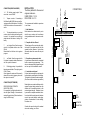
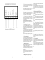
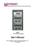
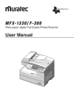
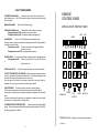
FAULT FINDING GUIDE
CUSTOMER HAD AN ALARM
Ask them to press the Full set button and tell you
what indicators are on. The LED's indicate the cause of the alarm and also the setting
status at the time.
MAINS LED FLASHING
Mains failure (Restore supply)
FM4000E
CONTROL PANEL
INSTALLATION INSTRUCTIONS
ZONE LED FLASHING (in exit)
Check that doors and windows are closed.
Flashing with tamper LED. (A detector has an open tamper).
Flashing with Battery LED. (The detectors battery needs replacing).
ZONES
PANIC
FIRE
ALARM LED ON
Full alarm. The LEDs indicate what caused the alarm.
If Engineer reset is programmed into the panel an engineer reset will be required before
the system can be re-armed.
Flashing with zone LED
A detector on soak test has triggered whilst the
system was armed.
Flashing without a zone LED An engineer reset is required.
FULL SET
BATTERY LED ON
The control panel's battery is disconnected or needs replacement.
Flashing with zone LED
Detector has a low battery. The zone LED will flash
to
indicate which one.
SIGNALLING LED ON
PART SET
The system is being blocked by a continuous transmission.
CONTACT TRANSMITTER NOT WORKING Check the magnetic contact is operating
correctly. Open lid and check what zone it should be on. Go into the panel engineer mode
and check if it has been programmed onto the correct zone.
Note: the panel will not allow you to program a detector onto two zones. When programmed onto a zone any previous zone allocation will be deleted.
PIR NOT WORKING
The detector needs 6 minutes to settle on power up.
Set the control into operator walk test mode and walk test the detector with the
cover removed. Removing the cover opens the tamper and overrides the 2 minute inhibit
timer.
If the test jumper inside is fitted and the cover replaced it overrides the 2 minute inhibit,
but allows you to walk test it without a tamper alarm.
OFF
TAMPER
SIGNALLING
ALARM
LOW
BATTERY
MAINS ON
CUSTOMER HAS FORGOTTEN THEIR CODE
Open the panel and short out the MEM
jumper. The user and engineer codes will be restored to the factory defaults 1234 & 4679.
No other programming is affected.
FM Electronics Ltd Manufacturer of quality wireless products
CI-146 ISS 1
11
1. Label detectors.
Each detector has a label inside for you to
write the zone number onto for reference
during installation and for later service reference.
9.
Dialler trigger output. Is provided for
triggering an autodialler. This output goes to
0v on full alarm.
Once triggered it remains until the panel is
disarmed, so as not to trigger any more until
the system is turned off.
_
_
1A AUX
L.S.
Consider the ease of wiring to the external
siren when making your choice.
1
Alarm
outputs
RSSI
RESET
ANTENNA
GROUND
CONNECTION (BOTTOM EDGE)
Metal objects cause radio reflections which
oppose the signal being received from the
detector with a resultant reduction in the
received signal strength. Metalwork close
by can result in complete cancellation, therefore do not site the control panel or detectors
near to large metal objects, metal piping,
girders, concentrations of mains cabling,
fuse boxes etc.
8
7
6
5
4
3
2
1
TAMPER
4. Locate the control panel
For best radio coverage the control panel is
best located at a central point in the building.
The higher it is the better for radio reception.
(Do not mount at floor level on a ground floor)
RECEIVED SIGNAL STRENGTH
INDICATION (RSSI)
For connection to a digital voltmeter to indicate the Signal Strength of a transmission
received from a detector. (Refer to section on
using the RSSI output).
EXIT
SOUNDER
Volume level
adjust
1
2
3
4
5
6
7
8
9
2A BAT
MEM
Jumper
3. Complete a system record sheet
A system record sheet should be completed
before commencing programming. This
acts as a reference when programming and
can form part of the installation records.
8.
-ve Strobe. Goes from open circuit to
0v in alarm to operate a strobe. Remains on
until the system is disarmed.
FUSES
2. Complete the User Record
The back page of the user instruction booklet should be completed and left with the
operator for their reference. It gives them
information about the zones and entry exit
times etc.
7.
-ve to trigger Siren. Goes from open
circuit to 0v to operate a bell or siren. Max
500mA.
Resets after the bell time set in engineer
program.
++
17V a.c.Input
6.
This terminal provides a +ve output
on alarm, which is reset next time the panel
is armed. It is provided for use with hard
wired detectors that have a latching LED
facility.
CONNECTIONS
+ LATCH
-ve SIREN
-ve STROBE
-ve DIALLER
The recommended installation procedure
is as follows:
-ve TAMPER RETURN
5
Tamper -ve return. If connecting a
Self Actuating Bell (SAB) then connect the
-ve tamper return to this terminal. If not fitting
a SAB this terminal must be connected to ve Aux.
Link 5 to 4 if -ve
from SAB is not
connected to 5.
1-4
12V Auxiliary supply output. Maximum load current 500mA
12V AUX
Max 500mA
INSTALLATION
The factory defaults for the user and
engineer codes are:USER CODE = 1 2 3 4
ENG CODE = 4 6 7 9
CONNECTIONS (RIGHT HAND SIDE)
+
-
10
VOLTMETER
CONNECTION
1
3
5
7
Connections on the FM4000 main board
Complete a system record sheet before making any changes.
Once programmed the program is stored in
none volatile memory, so data will remain
stored even in the event of complete power
failure.
The Panel may be temporarily sited whilst
a test is carried out to verify the reception
from distant detectors.
Strobe -
When satisfied the panel must be fixed
using the three fixing points provided.
Strobe +
Tamper return
Tamper feed
Bell sw+
Bell sw-
-ve Hold off
+ve Hold off
SAB CONNECTION TO THE FM4000
8
9. Radio test using the RSSI output
To measure the signal strength received from
a detector.
i)
Connect a Voltmeter to the RSSI output
terminals.
ii)
Press the reset button next to the RSSI
terminals. The voltmeter should now read zero
volts.
iii)
Go to the detector and operate the learn
jumper.
iv)
Return to the panel. The voltmeter now
displays a voltage representing the strength of
the transmission received.
It will ignore any other transmissions and
only respond to the learn message or a Panic
or Off message from a remote control or panic
button.
Mains supply to the control panel must be
provided by a competent electrician to the
current issue of the IEE regulations.
A 12v sealed lead acid stand-by battery
should be connected, after all wiring has
been completed and tested. 12v 1.9AH is
recommended.
5. Program detectors onto the panel
Each detector has an internal "Learn"
jumper.
To add a detector to the system:
Go into the engineer program. Select the
zone number. Short out the learn jumper on
the detector. Remove the learn jumper after
programming
The detector transmits its identity together
with a learn bit. The panel stores the detectors identity code and adds it to the chosen
zone.
(Refer to engineer programming section)
The voltage reading should be a minimum of
1.0v.
The readings for each detector can be recorded on the system record sheet for future
reference.
6. Carry out range test
If you keep a 4174 remote control for testing,
you can program this onto the system and
then go to each detector location in turn and
verify that the control can be armed and
disarmed from all detector locations.
10. Full system test
A walk test facility is provided in the Operating
instructions. This may be used to do a test of the
detectors only.
Once the Sounders and dialler have been
connected and the installation completed a full
test with remote signalling should be carried
out.
7. Mount the detectors
Refer to the detector instructions for recommended mounting positions.
As reflections from metalwork act to cancel
the transmission, avoid siting near to any
metalwork.
Reflections like this can often be overcome
by a small movement in position of 15 to
20cm.
8. Making panel program changes.
9
2
step.
Note: The Full set button must be pressed
to exit from each program step.
Until the Full Set button is pressed any
key press just changes your choice of
option.
PROGRAMMING
1. Enter the engineers code 4 6 7 9
The Alarm led will flash slowly to indicate
that you are in the program mode.
Key in the next program Number you wish
to change.
2. Key in the two digit program number.
(The zone led's indicate which option is
set.)
When all programming is complete Key
in 48 to exit engineer mode
3. Key in the option required
(The zone led's indicate your choice)
00 INVERT SIREN OUTPUT
Normally -ve applied in alarm.(0v in
alarm)
0
=
-ve applied in alarm
1
=
-ve removed in alarm
4. Press the Full Set key
program step.
to exit that
5. When finished with programming key in
48 to exit engineer mode.
ERROR CORRECTION VIA PART SET KEY
If you accidently enter an engineer program number and change an option value,
you can undo the change by pressing the
Part Set key before exiting the program
step via the Full Set key.
EXAMPLE: To set the Full set entry timer
to 1 minute.
Key in 4 6 7 9 The alarm indicator will
illuminate to indicate that you are now in
engineer program mode
Key in 1 2
To select Full set exit time
(program No. 12.)
Key in 6 To select the 1 minute option.
Zone 6 LED indicates your choice
REMOTE ENGINEER RESET
FACILITY
When an alarm occurs which requires an
engineer reset, the user can call the Central Station and obtain the access code
number to key in to the panel.
The panel zone LED's will illuminate randomly.
From the LED's the Central Station operator can refer to a reference table and instruct the user what code to enter to perform an engineer reset.
Next time the alarm operates the reset
code number will have changed.
LEARNING DEVICES
When installing the system you may find
it easier to label each detector with its
zone number and learn them into the
panel before installation. Once programmed into the panel's memory, the
information will not be lost even when
power is removed from the panel.
01 PROGRAM DEVICES ONTO ZONE 1
Select program number 01. The numbered LED's will indicate how many detectors are already on that zone. eg. if
LED's 1, 2 and 3 are lit then there are 3
devices on that zone.
To delete all detectors from that zone
press Part set & O keys together.
To add a detector to a zone, briefly short
out the learn jumper on the detector and
ensure that the learn pins are not left
permanently shorted.
The panel will emit 2 short blips to indicate that it has learnt the detector and the
Press the Full Set button to exit program
3
8
1= none 2= once 3= twice 4=always*
Press the full set key to exit
1= Yes O= No*
Press the full set key to exit.
34 JAMMING
1 = Jamming generates a full alarm when
set
O= indicator only*
Press the full set key to exit.
(Jamming is signalled to the dialler outputs.)
44 RESTORE ENTIRE NV RAM TO FACTORY DEFAULT VALUES
Short out the MEM link while keying in 44.
All zone LED's will come on, the panel will
emit a long bleep and will go out of engineering mode into the day state.
WARNING: This will delete all detectors
from the system.
35
MAINS FAILURE & PANEL LOW
BATTERY PREVENTS ARMING
1 = Mains failure or Panel battery failure
prevents arming.
O = Does not prevent arming*
Press the full set key to exit
45 AUDIBLE RECEIVE MODE
The output from the receiver can be heard
on the panel loudspeaker.
Press the full set key to exit.
36 REMOTE CONTROL UNSETS
ONLY IN ENTRY
1= Unset only after entry timer has been
started.
O= Unset not inhibited*
Press the full set key to exit.
46 DISPLAY ENGINEERS LOG
Press keys 1 to 8 to view the last 8 events.
Most recent is displayed on key 1.
Key 9 shows the last "First to Alarm"
Press the full set key to exit.
47 CHANGE ENGINEERS ACCESS CODE
Key in a 4 digit code twice.
37 DIALLER DELAYED
(20 second abort time)
1= Delayed
O= Instant *
Press the full set key to exit
48 LEAVE ENGINEER MODE
If any devices have their tampers open,
the display shows which zones are tampered and will generate an error beep.
The tampers must be restored before
leaving engineer mode by pressing 48
again.
38 NO EXTERNAL BELL OR DIALLER IN
PART SET
(Internal bells only in Part Set).
1= Internal sounder only in Part Set.
O= Dialler and siren In both full or part set*
Press the full set key to exit
will indicate that one sensor has been
programmed in.
new total of devices on that zone will be
displayed on the numeric LED's.
Press the Full Set key to exit.
Up to eight sensors can be programmed
onto the fire zone by simply shorting out the
learn jumper of each one in turn.
Press the Full Set key to exit
02
PROGRAM DEVICES ONTO
ZONE 2
03
PROGRAM DEVICES ONTO
ZONE 3
11 REMOTE CONTROLS
To delete all Remote Controls press Part
& 0 keys together.
04
PROGRAM DEVICES ONTO
ZONE 4
To add a remote control press the Panic
button. The panel will emit 2 short blips to
indicate that it has read the remote control
and LED 1 will indicate that one remote has
been programmed in.
You can add up to 8 remote controls by
simply pressing each one in turn.
Press the Full Set key to exit.
05
PROGRAM DEVICES ONTO
ZONE 5
06
PROGRAM DEVICES ONTO
ZONE 6
07
PROGRAM DEVICES ONTO
ZONE 7
12 FULL SET EXIT TIME
1= 2 secs
2= 1O secs
4= 3O secs 5= 45 secs
7= 2 mins 8= 3 mins
Press Full Set to exit
08
PROGRAM DEVICES ONTO
ZONE 8
09 RADIO PANIC BUTTONS
To delete all Panic Buttons already on this
option press Part & 0 keys together.
To add a new device press the panic button.
The panel will emit 2 short blips to indicate
that it has read the panic button and LED 1
will indicate that one PA has been programmed in.
* = FACTORY DEFAULT
13 PART SET EXIT TIME
1= 2 secs
2= 5 secs
3= 1O secs*
4= 15 secs 5= 20 secs 6= 30 secs
7= 1 mins 8= As full set exit time.
Press Full Set to exit
You can add up to 8 PA's to the panic zone
by simply pressing each one in turn.
Press the Full Set key to exit.
42 ENGINEER RESET
1= Engineer reset
O= No*
Press the full set key to exit.
10 FIRE ALARM DEVICES
To delete all Fire sensors press Part & 0
keys together.
43 REARMING
To add a fire sensor, short out the learn
jumper.
14 ENTRY TIME
1= 1 sec
2=10 secs
4= 30 secs* 5= 40 secs
7= 1 min
8= 2 min
Press Full Set to exit
3= 20 secs
6= 50 secs
15 BELL DURATION
1= Silent 2= 15 secs 3= 2 mins
4= 3 mins
5=10 mins 6= 15 mins
7= 20 mins* 8=Continuous
Press Full Set to exit
The panel will emit 2 short blips to indicate
that it has read the sensor and zone 1 LED
7
3= 2O secs*
6= 1 min
4
permit via program No.19.
16 BELL DELAY
1= 0 mins* 2= 1 min
4= 4 mins
5= 5 mins
7=7 mins*
8= 10 mins
Press Full Set to exit
3= 3 mins
6=6 mins
17 FULL SET ZONES
The factory default is all zones active.
The zone LED's indicate which zones are
active in full set.
Use the keys 1 to 8 to select or deselect
zones. The 0 key deletes all.
Press the full set key to exit.
18 PART SET ZONES
The factory default is zones 1 to 4 active.
The zone LED's indicate which zones are
active in part set.
Use the keys 1 to 8 to select or deselect
zones. The 0 key deletes all.
Press the full set key to exit.
19 OMIT PERMIT ZONES
(The zones that the user is allowed to omit)
The factory default is all zones allowed to
be omitted except zone 1.
The zone LED's indicate which zones are
allowed to be omitted.
Use the keys 1 to 8 to select or deselect
zones. The 0 key deletes all.
Press the full set key to exit.
2O FINAL EXIT ZONES
(Zones that start the entry time)
The factory default is zone 1 only.
The zone LED's indicate which zones will
start the entry timer.
Use the keys 1 to 8 to select or deselect
zones.
The 0 key deletes all.
Press the full set key to exit.
21 WALK THROUGH ZONES
The factory default is none.
The zone LED's indicate which zones are
walk through during entry.
Use the keys 1 to 8 to select or deselect
walk through zones.
The 0 key deletes all.
Press the full set key to exit.
22 IGNORE ZONE IF FIRST TO ALARM
(Double Knock)
Alarm only if two zones are triggered.
The factory default is none.
The zone LED's indicate which zones are
double knock.
Use the keys 1 to 8 to select or deselect
double knock zones.
The 0 key deletes all.
Press the full set key to exit.
23 AUXILIARY ZONES
Technical alarm. ie. Freezer giving internal audible and technical alarm channel
of dialler.
The factory default is none.
The zone LED's indicate which zones are
auxiliary zones.
Use the keys 1 to 8 to select or deselect
aux. zones.
The 0 key deletes all.
Press the full set key to exit.
24 24 HOUR ZONES
The factory default is none.
The zone LED's indicate which zones are
24 hour.
Use the keys 1 to 8 to select or deselect
24 hour zones.
The 0 key deletes all.
Press the full set key to exit.
NOTE: If you do not want a 24 hour zone
to be omitted, remove the zone from omit
5
25 SOAK TEST ZONES
The factory default is none.
The zone LED's indicate which zones are
on soak test.
Use the keys 1 to 8 to select or deselect
soak test zones.
The 0 key deletes all.
Press the full set key to exit.
26 CHIME ZONES
The factory default is none.
The zone LED's indicate which zones are
on chime.
Use the keys 1 to 8 to select or deselect
chime zones.
The 0 key deletes all.
Press the full set key to exit.
27 P.A. SILENT / AUDIBLE
The
factory default is audible.
1= Silent
O= Audible *
Press the full set key to exit.
28 DOUBLE BUTTON P.A.
(To activate a panic from a remote control, both PA & OFF buttons must be
pressed simultaneously)
The factory default is single button.
1= Double
O= Single*
Press the full set key to exit.
eg. The Part Set button becomes the
alarm system in the flat & the Full set
button is a separate alarm system in
the office. In this mode the user can
set either one or the other, or both
systems by selection when arming.
1 = Select Upstairs/Downstairs mode.
O= Normal Part / Full set mode.*
Press the full set key to exit.
31 8 SECOND STROBE WHEN FINAL
SET AND UNSET
If selected the strobe output operates
for 8 seconds at the moment the panel
is full set. i.e. when the exit timer
terminates.
The strobe also operates for 8 seconds when the panel is Unset from
Full Set.
1 = 8 sec. Strobe
0 = No 8 second
strobe
Press the full set key to exit.
32 COURTESY STROBE IN FULL SET
ENTRY / EXIT
If selected the strobe output terminal
8 operates when Full setting the panel.
The strobe output also operates for
the entry time when unsetting from
Full Set.
(If a mains relay was connected via
this output a mains courtesy light could
be switched on by disarming from
outside with a remote control.)
1= Courtesy strobe on
O=off*
Press the full set key to exit.
29 SILENT PART SET
1= Silent
O= Audible*
Press the full set key to exit.
30 UPSTAIRS / DOWNSTAIRS
This option tells the panel to accept part
set button as a separate alarm system.
6
33 WALK THROUGH ZONES BECOME FINAL EXIT IN PART SET
To prevent false alarms in part set it is
often useful to make walk through
zones initiate the entry timer.