1
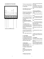
1. Label detectors.
Each detector has a label inside for you to
write the zone number onto for reference
during installation and for later service reference.
9.
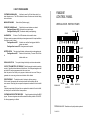
Dialler trigger output. Is provided for
triggering an autodialler. This output goes to
0v on full alarm.
Once triggered it remains until the panel is
disarmed, so as not to trigger any more until
the system is turned off.
_
_
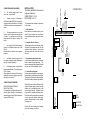
1A AUX
L.S.
Consider the ease of wiring to the external
siren when making your choice.
1
Alarm
outputs
RSSI
RESET
ANTENNA
GROUND
CONNECTION (BOTTOM EDGE)
Metal objects cause radio reflections which
oppose the signal being received from the
detector with a resultant reduction in the
received signal strength. Metalwork close
by can result in complete cancellation, therefore do not site the control panel or detectors
near to large metal objects, metal piping,
girders, concentrations of mains cabling,
fuse boxes etc.
8
7
6
5
4
3
2
1
TAMPER
4. Locate the control panel
For best radio coverage the control panel is
best located at a central point in the building.
The higher it is the better for radio reception.
(Do not mount at floor level on a ground floor)
RECEIVED SIGNAL STRENGTH
INDICATION (RSSI)
For connection to a digital voltmeter to indicate the Signal Strength of a transmission
received from a detector. (Refer to section on
using the RSSI output).
EXIT
SOUNDER
Volume level
adjust
1
2
3
4
5
6
7
8
9
2A BAT
MEM
Jumper
3. Complete a system record sheet
A system record sheet should be completed
before commencing programming. This
acts as a reference when programming and
can form part of the installation records.
8.
-ve Strobe. Goes from open circuit to
0v in alarm to operate a strobe. Remains on
until the system is disarmed.
FUSES
2. Complete the User Record
The back page of the user instruction booklet should be completed and left with the
operator for their reference. It gives them
information about the zones and entry exit
times etc.
7.
-ve to trigger Siren. Goes from open
circuit to 0v to operate a bell or siren. Max
500mA.
Resets after the bell time set in engineer
program.
++
17V a.c.Input
6.
This terminal provides a +ve output
on alarm, which is reset next time the panel
is armed. It is provided for use with hard
wired detectors that have a latching LED
facility.
CONNECTIONS
+ LATCH
-ve SIREN
-ve STROBE
-ve DIALLER
The recommended installation procedure
is as follows:
-ve TAMPER RETURN
5
Tamper -ve return. If connecting a
Self Actuating Bell (SAB) then connect the
-ve tamper return to this terminal. If not fitting
a SAB this terminal must be connected to ve Aux.
Link 5 to 4 if -ve
from SAB is not
connected to 5.
1-4
12V Auxiliary supply output. Maximum load current 500mA
12V AUX
Max 500mA
INSTALLATION
The factory defaults for the user and
engineer codes are:USER CODE = 1 2 3 4
ENG CODE = 4 6 7 9
CONNECTIONS (RIGHT HAND SIDE)
+
-
10
VOLTMETER
CONNECTION