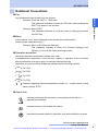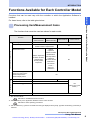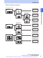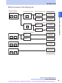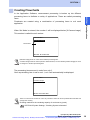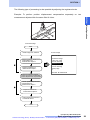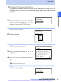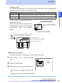
1
Artisan Technology Group is your source for quality new and certified-used/pre-owned equipment • FAST SHIPPING AND DELIVERY • TENS OF THOUSANDS OF IN-STOCK ITEMS • EQUIPMENT DEMOS • HUNDREDS OF MANUFACTURERS SUPPORTED • LEASING/MONTHLY RENTALS • ITAR CERTIFIED SECURE ASSET SOLUTIONS SERVICE CENTER REPAIRS Experienced engineers and technicians on staff at our full-service, in-house repair center WE BUY USED EQUIPMENT Sell your excess, underutilized, and idle used equipment We also offer credit for buy-backs and trade-ins www.artisantg.com/WeBuyEquipment InstraView REMOTE INSPECTION LOOKING FOR MORE INFORMATION? Visit us on the web at www.artisantg.com for more information on price quotations, drivers, technical specifications, manuals, and documentation SM Remotely inspect equipment before purchasing with our interactive website at www.instraview.com Contact us: (888) 88-SOURCE | [email protected] | www.artisantg.com OPERATION MANUAL Using This Manual Application Software F500-UME 1 Basic Operating Procedures 2 Processing Items Setting Procedure 3 Test/Measurement Execution 4 Other Functions 5 System Settings 6 Communicating with External Devices 7 Appendix This manual explains basic operations, such as installing the Application Software, setting up inspection processes, and communications with external devices. Artisan Technology Group - Quality Instrumentation ... Guaranteed | (888) 88-SOURCE | www.artisantg.com INTRODUCTION Using This Manual Using This Manual Operation Procedure and Reference Manual 2 Using This Manual 3 Hierarchical Structure and Printout Method for Manual 3 Full-Text Search Method 3 Editor's Note 5 Page Format 5 Notational Conventions 6 Functions Available for Each Controller Model Processing Item Selection Guide 8 10 Input image Items 11 Position Compensation Items 12 Measurement Items 13 Measurement Support Items 21 Branching Control Items 21 Results Output Items 21 Results Display Items 22 F500 Operation Manual/INTRODUCTION Using This Manual Artisan Technology Group - Quality Instrumentation ... Guaranteed | (888) 88-SOURCE | www.artisantg.com 1 INTRODUCTION Operation Procedure and Reference Manual The following shows main contents of operation steps and manuals.Select the manual suitable Connecting (Supplied with the Controller) F500 Wiring 747A The Setup Manual provides: - Information for safety use of controller - Procedures from package content check and installation up to connection of controller - Information such as functions and specifications of controller and peripheral devices Installing Vision Mate Series Software (CD-ROM) Vision Composer Net Setting Inspection Conditions Operation Manual The Operation Manual provides: - Method of operating the controller from Vision Composer Net - Explanation of functions of Vision Composer Net INTRODUCTION Operation Procedure and Reference Manual for your purpose and read it before starting operation. Tutorial Manual Checking Settings and Starting Measurement The Tutorial Manual provides: Exercises for basic operations of Vision Composer Net (㶎) 㶎㩷 Two courses are available: Basic Course to learn how to perform measurement and adjustment, and Advanced Course to learn about a series of operations, starting from creation of Flow up to measurement and adjustment. It is recommended that users begin with the Basic Course. Application Software Operation Manual The Operation Manual provides: - Installation method of application software - Basic operating procedures - Setting method of each processing item - Communication method with external devices Outputting Data to External Device Reverse Manual The Reverse Manual provides: Examples of vision sensor use Useful methods for vision sensor use Customize Manual The Customize Manual provides the information necessary for customization and explains the macro function. F500 Operation Manual/INTRODUCTION Using This Manual Artisan Technology Group - Quality Instrumentation ... Guaranteed | (888) 88-SOURCE | www.artisantg.com 2 INTRODUCTION Using This Manual This manual consists of various PDF files. The hierarchical structure of the manual is shown on the next page. Entire links in the manual are shown by Acrobat’s index function, and the initial screen provides links to the front page of each section, and the front page of each section provides links to each item in that section The manual can be printed one file at a time. Display the file to be printed out, open Acrobat's print dialog box, and then print the file according to the procedure displayed. INTRODUCTION Using This Manual Hierarchical Structure and Printout Method for Manual Full-Text Search Method The catalogue function of Acrobat is used to enable full-text search in the entire Application Software Operation Manual and Vision Composer Net Operating Manual. Select [Edit] - [Search] to display the search panel. Enter "In the index named f500-cd.pdx" in [Where would you like to search?] and start search. When displaying a manual using Adobe Reader, this function cannot be used unless Adobe Reader (full version) has been installed. F500 Operation Manual/INTRODUCTION Using This Manual Artisan Technology Group - Quality Instrumentation ... Guaranteed | (888) 88-SOURCE | www.artisantg.com 3 INTRODUCTION Linked pages As one file Only cover page Common block Using This Manual 1. Input image Camera image Change filtering Switch camera Filtering Again 2. Position compensation SECTION 1 Basic Operating Procedures Binary Position Compensation EC Position Compensation Edge Position Compensation Model Position Compensation Circle Position Compensation Reset Scroll Scroll Model Position Compensation# 3. Measurement Binary Defect Density Defect SECTION 2 Processing Items Setting Procedures Classification EC Defect . . . . . . Rotation Search INTRODUCTION Using This Manual Initial Screen Option block Circular angle 4. Measurement Support SECTION 3 Test/Measurement Execution Calculation Elapsed Time Wait Get Unit Data Set Unit Data Trend Monitor Data logging 5. Branch Control Conditional Branching DI branching End 6. Results Output SECTION 4 Other Functions Memory card data DO data DO judgement Host link data Normal data 7. Results Display Display string SECTION 5 System Settings Display measure Display judge Display item Display figure Display time Display Line, Display Box, Display Circle, and Display Cursor Display Last NG Image SECTION 6 Communicating with External Devices Parallel Interface Normal Serial Interface Host Link Serial Interface Serial Interface Menu Operations SECTION 7 Appendix Communication with Vision Conductor F500 Operation Manual/INTRODUCTION Using This Manual Artisan Technology Group - Quality Instrumentation ... Guaranteed | (888) 88-SOURCE | www.artisantg.com 4 INTRODUCTION Editor's Note Title of each section Header SECTION 2 Processing Items Setting Procedures Indicates the contents of the page. Gravity and Area Overview The 256-gradation images read by the Camera are converted into binary black-and-white images and step measurement is performed on the white pixels. 7 Describes the overview and operation flow of the section. The size (area) and position (center of gravity) of the measurement object can be detected. Use [Pattern detection] to distinguish between measurement object shapes. SECTION 2 Measurement/Gravity and Area Set the level for converting 256-gradation images into binary images. The Controller uses the white pixels to measure the object. Adjust the binary level so that the object is displayed as white pixels. [Gravity and area/Binary] Lower limit 1. Move the cursor to the upper value and Index Label step1 1 Setting the Binary Level INTRODUCTION Editor's Note Page Format Indicates to which section the current page belongs and the contents of the page. Sub-header Upper limit Binary level Upper [255] Lower [128] Riverse Auto OK use the Left and Right Keys to adjust the value. 2. Use the same method to change the lower value. 3. Select [End]. Set the upper and lower limits so that the measurement object is displayed as white pixels. [Auto] The Contoller automatically sets the binary level [Reverse] Reverses black and white in the display Screen display Indicates the status of the screen displayed on the left side. Section title/Processing Item F500 Operation Manual/SECTION 2, 3. Measurement Binary defect inspection 3 Operation procedure and supplementary explanation Describes the processing items in "SECTION 2 Processing Items Setting Procedures". Indicates operation procedures and functions of operation keys. Helpful information regarding operation and reference pages is introduced here using symbols. Menu Hierarchy Shows the menu hierarchy up to the corresponding operating screen. Overview and important point in application procedures * This page does not exist. F500 Operation Manual/INTRODUCTION Using This Manual Artisan Technology Group - Quality Instrumentation ... Guaranteed | (888) 88-SOURCE | www.artisantg.com 5 INTRODUCTION Notational Conventions Key Example: Press the SHIFT + TRIG Keys. This statement indicates to press the TRIG Key while pressing the SHIFT Key down on the console. Example: Select [SET]. This statement indicates to move the cursor to [Setting] and press the ENT Key. Menu INTRODUCTION Editor's Note Key operations are performed from the console. In this manual, menu items displayed on the screen are enclosed with [ ]. Submenus are separated using “/”. Example: Move to [SYS/Camera Settings]. This statement indicates to select the [Camera Settings] from [System] to move to the Camera Settings screen. Operation procedure Operation steps are numbered to indicate their order. A supplementary explanation of the behavior, display or operation of the Controller after the execution of a step is given in the lines following the step. Steps that vary with controller models are indicated by the following symbols. For F210 For F250 For F270 For F500 Contents regarding Ethernet-compatible models (i.e. models whose model name contains "ETN") Visual Aids Indicates points that are important in using product functions or in application procedures. Indicates where to find related information. Indicates information helpful in operation, such as the definition of terms. F500 Operation Manual/INTRODUCTION Using This Manual Artisan Technology Group - Quality Instrumentation ... Guaranteed | (888) 88-SOURCE | www.artisantg.com 6 INTRODUCTION Symbols The following symbols used in the manual may differ from those actually displayed in the screen. INTRODUCTION Editor's Note In this case, they must be read as follows. Symbols in manual Screen display ↓ D, DWN, Down ← L, LEFT, Left → R, RIGHT, Right ° Not displayed ± +/- θ Rotation, Angle µ u F500 Operation Manual/INTRODUCTION Using This Manual Artisan Technology Group - Quality Instrumentation ... Guaranteed | (888) 88-SOURCE | www.artisantg.com 7 INTRODUCTION Functions Available for Each Controller Model Functions that can be used vary with the controller to which the Application Software is For those items, refer to the table given below. Processing item/Measurement items The functions that cannot be used are shown for each model. Controller Function F210-C10/C15 F210-C10-ETN F500-C10-ETN F500-C15-ETN Input image Items Position Compensation Items Measurement Items F250-C50/C55 F270-C10/C15 No Non-usable processing items Circle Position Compensation Model Position Compensation No Pattern Inspection Rotation Position Classification Pattern Inspection Density Defect Rotation Position Inspection Classification Quest Character Density Defect Verification*3 Inspection Lot Number OCV1*3 OCR for 1 character*3 No Measurement Support Items Branching Control Items Results Output Items Results Display Items Run Function Mode *1 Nonstop adjust mode INTRODUCTION Functions Available for Each Controller Model installed. No No Yes 1-line fast mode No 2-line random trigger mode No Macro Function *2 Yes (Select one of the modes.) Yes *1: Run Function Mode SECTION 3 Test/Measurement Execution *2: Can be used only if the Application Software has the macro function. SECTION 1 Basic operating procedures *3: Can be used if the [+] mark is not attached to the type displayed when [SYS] - [System information] -[Controller] is selected. F500 Operation Manual/INTRODUCTION Using This Manual Artisan Technology Group - Quality Instrumentation ... Guaranteed | (888) 88-SOURCE | www.artisantg.com 8 INTRODUCTION Serial Interface Menu Operations Controller Interface RS-232C or RS-422 USB Ethernet F210-C10/C15 z × × F250-C50/C55 z × z* F270-C10/C15 z × z* F210-C10-ETN/C15-ETN z z { F500-C10-ETN/C15-ETN z z { z: Only one interface can be used. It is not possible to use two or more interfaces at the same time. {: For Vision Composer Net only *: Not possible to connect to Vision Composer Net. INTRODUCTION Functions Available for Each Controller Model The interfaces that can be used are shown below for each model. F500 Operation Manual/INTRODUCTION Using This Manual Artisan Technology Group - Quality Instrumentation ... Guaranteed | (888) 88-SOURCE | www.artisantg.com 9 INTRODUCTION Processing Item Selection Guide This software provides various processing items so that you can choose according to your This section gives guidance regarding what items should be selected for what cases. This is guidance only. To check whether measurement can be performed correctly, actual measurement must be performed. For details on processing items, refer to SECTION 2 Processing items Setting Procedure. Input image Items Go to p.11 Position Compensation Items Go to p.12 Measurement Items Go to p.13 Positioning (Measurement Objects Not On An Angle) Go to p.13 Positioning (Measurement Objects On An Angle) Go to p.14 Front/Rear Inspection Go to p.14 Presence/Absence Inspection Go to p.15 Dimensional Inspection/Measurement Go to p.16 Chip/Bur Inspection Go to p.16 Character Reading Go to p.16 Character Verification Go to p.17 Character Inspection Go to p.17 Defect Inspection (Plain Background) Go to p.18 Defect Inspection (Characters, Drawing and Patterns on Background) Go to p.19 Quantity Inspection/Measurement Go to p.19 Foreign Matter Inspection Go to p.20 Classification Go to p.20 BGA Inspection Go to p.20 Measurement Support Items Go to p.21 Branching Control Items Go to p.21 Results Output Items Go to p.21 Results Display Items Go to p.22 INTRODUCTION Processing Item Selection Guide application. F500 Operation Manual/INTRODUCTION Using This Manual Artisan Technology Group - Quality Instrumentation ... Guaranteed | (888) 88-SOURCE | www.artisantg.com 10 INTRODUCTION Input image Items Camera Image Change filtering Filtering Again Camera 0 Camera 1 Filtering 0 2 Camera Image 0 Image buffer (for Camera 1) *Second filtering Camera selection Camera 3 Image buffer (for Camera 0) Image buffer (for Camera 2) Image buffer (for Camera 3) Filtering 1 Image 1 *: When [Filtering again] is selected Processing item INTRODUCTION Processing Item Selection Guide Switch camera Remark Inputting Camera Images This section describes how to make the series of settings required when storing conditions for reading Camera images and storing measurement object images to [Image 0] or [Image 1]. A Camera image must be read to perform measurements, and Camera image is thus set for unit 0 by default.Do not delete Camera image from unit 0 or change it to another processing item. Switch camera The Switch Camera processing item is used to switch the Camera (image buffer) from which images will be stored to [Image 0] and [Image 1]. New images are not read from the Camera. The filtering settings will be changed at the same time. Changing Filtering The Change Filtering processing item is used to change only the filtering settings for [Image 0] and [Image 1]. New images are not read from the Camera. Filtering Again The Filtering Again processing item is used to add filtering to an image.Images can be sent from [Image 0] to [Image 1] or from [Image 1] to [Image 0] to add filtering to the image when it is transferred. This processing item is used if stronger smoothing is required to eliminate noise or increase edge enhancement. F500 Operation Manual/INTRODUCTION Using This Manual Artisan Technology Group - Quality Instrumentation ... Guaranteed | (888) 88-SOURCE | www.artisantg.com 11 INTRODUCTION Position Compensation Items Which mark is used for position compensation? Box Cross point of lines How is the mark? Processing Items Loss of lines Extra lines in surrounding area EC Position Compensation No loss of lines No extra lines in surrounding area Edge Position Compensation Which controller is used? Circle Inclined F250, F270 Circle Position Compensation F210, F500 Model Position Compensation # M M Not inclined EC Position Compensation M Other INTRODUCTION Processing Item Selection Guide Position compensation Shape change Binary Position Compensation Which controller is used? No shape change F250, F270 Model Position Compensation F210, F500 Model Position Compensation # Other Processing item Remark Reset Scroll The Reset Scroll processing item is used to return images that were scrolled using position displacement compensation to their original position (the position when read to the image buffer). Example: To perform position displacement compensation separately on two measurement objects within the same field of vision. Scroll It can be used when the required results cannot be achieved with position compensation processing items. The Scroll processing item scrolls an image based on the measured values from other units. It can be used in combination with other general measurement processing items. F500 Operation Manual/INTRODUCTION Using This Manual Artisan Technology Group - Quality Instrumentation ... Guaranteed | (888) 88-SOURCE | www.artisantg.com 12 INTRODUCTION Measurement Items Positioning (Measurement Objects Not On An Angle) Box Cross point of lines Processing Items How is the mark? Loss of lines Extra lines in surrounding area EC Positioning What kind of line? No loss of lines No extra lines in surrounding area Horizontal/vertical How many measuring points? One Edge Position_1 Multiple Edge Position_8 Diagonal T-Edge Position INTRODUCTION Processing Item Selection Guide Which mark is used for positioning? Circle EC Positioning How is the mark? Other Slight shape change Flexible Search Excessive shape change Gravity and Area What position is Is the entire mark clearly seen? measured? No shape change Position of one object Sometimes partially hidden ECM Search How about inspection accuracy? Entire mark is clear Relative position of two objects In units of pixels Gray Search In units of sub-pixels Precise Search Relative Search F500 Operation Manual/INTRODUCTION Using This Manual Artisan Technology Group - Quality Instrumentation ... Guaranteed | (888) 88-SOURCE | www.artisantg.com 13 INTRODUCTION Positioning (Measurement Objects On An Angle) Which mark is used for positioning? Processing Item EC Positioning Circle Circular angle How is the mark? Shape change Other Gravity and Axis Which controller is used? No shape change F250, F270 Rotation Positioning F210, F500 Rotation Search INTRODUCTION Processing Item Selection Guide Box Cross point of lines Front/Rear Inspection How to judge front/rear? By mark A B Does mark color change? Inclined? Sometimes No inclined A B Processing Items Rotation Search A Not inclined Pattern Inspection A Yes A B A B Flexible Search By color density Density Data F500 Operation Manual/INTRODUCTION Using This Manual Artisan Technology Group - Quality Instrumentation ... Guaranteed | (888) 88-SOURCE | www.artisantg.com 14 INTRODUCTION Presence/Absence Inspection Yes Inclined? Processing Items Inclined Rotation Search Is the entire mark clearly seen? Not inclined Yes Pattern Inspection Sometimes partially hidden ECM Search Is the entire mark clearly seen? Yes, but may change slightly Yes Sometimes partially hidden Flexible Search INTRODUCTION Processing Item Selection Guide Has the mark to be judged been decided? ECM Search Is inspection region fixed? No Fixed Gravity and Area Not fixed Area (Var. Box) F500 Operation Manual/INTRODUCTION Using This Manual Artisan Technology Group - Quality Instrumentation ... Guaranteed | (888) 88-SOURCE | www.artisantg.com 15 INTRODUCTION Dimensional Inspection/Measurement Which direction? Processing Items Edge Width Diagonal Gravity and Area Chip/Bur Inspection Are any size variations other than chip/bur considered to make OK/NG judgement? Processing Items Yes OK INTRODUCTION Processing Item Selection Guide Vertical or horizontal Binary Defect Inspection NG Which controller is used? No OK OK F250, F270 Density Defect Inspection F210, F500 Density Defect Inspection # Character Reading How many characters are to be read? Processing Items Multiple Quest Character Verification One OCR for 1 Character F500 Operation Manual/INTRODUCTION Using This Manual Artisan Technology Group - Quality Instrumentation ... Guaranteed | (888) 88-SOURCE | www.artisantg.com 16 INTRODUCTION Character Verification Character type? Lot No. Lot Number OCV1 Characters other than lot Nos. Quest Character Verification Does character shape change? Special fonts, kana, Chinese characters Yes Flexible Search Are characters inclined? No Inclined Not inclined Rotation Search INTRODUCTION Processing Item Selection Guide General fonts Processing Items What character? Fine matching Character Inspection Is the character to be inspected inclined? Inclined Not inclined Processing Items Rotation Search Pattern Inspection F500 Operation Manual/INTRODUCTION Using This Manual Artisan Technology Group - Quality Instrumentation ... Guaranteed | (888) 88-SOURCE | www.artisantg.com 17 INTRODUCTION Defect Inspection (Plain Background) Level of defects How thick is the defect? Narrow Which controller is used? Processing Items F250, F270 Density Defect Inspection F210, F500 Density Defect Inspection# Is inspection region fixed? Wide Fixed Not fixed Defect Defect (Variable Box) Is inspection region fixed? Size of defects Fixed Not fixed Binary defect inspection INTRODUCTION Processing Item Selection Guide What are criteria for OK/NG judgement? Area (Var. Box) Number of defects Labeling Size of largest defect Label Data F500 Operation Manual/INTRODUCTION Using This Manual Artisan Technology Group - Quality Instrumentation ... Guaranteed | (888) 88-SOURCE | www.artisantg.com 18 INTRODUCTION Defect Inspection (Characters, Drawing and Patterns on Background) What kind of background? Does background move? Not fixed Fixed Processing Items Fine matching Fixed Pattern Inspection What state? Not fixed Pattern covers the entire measurement region Density Data Pattern consists of circles or lines EC Defect Inspection Pattern does not consist of circles and defects are almost circular INTRODUCTION Processing Item Selection Guide Defects within character, figure or pattern Is the line thickness of characters and figures fixed? EC Circle Defect Inspection Quantity Inspection/Measurement Are objects to be counted located in line? No Are objects to be inspected/measured circular? Circular Not circular Processing Items EC Circle Count Inspection Labeling Yes Edge Pitch F500 Operation Manual/INTRODUCTION Using This Manual Artisan Technology Group - Quality Instrumentation ... Guaranteed | (888) 88-SOURCE | www.artisantg.com 19 INTRODUCTION Foreign Matter Inspection By mark A Does mark shape change? Sometimes inclined No A B Inclined? Processing Items Rotation Search A Not inclined Pattern Inspection A Yes By color density Flexible Search Density Data INTRODUCTION Processing Item Selection Guide How to distinguish from wrong models? Classification Which controller is used? Processing Items F250, F270 Classification F210, F500 Classification# BGA Inspection Processing Item BGA Inspection F500 Operation Manual/INTRODUCTION Using This Manual Artisan Technology Group - Quality Instrumentation ... Guaranteed | (888) 88-SOURCE | www.artisantg.com 20 INTRODUCTION Measurement Support Items Processing item Remark The Calculation processing item is used to perform calculations using the results and measurement values for the processing items registered to the units. Elapsed Time The Elapsed Time processing item finds the amount of time (in ms) that has passed since the measurement trigger was input. Wait The Wait processing item temporarily stops the execution of the flowchart and holds processing for a set time. Processing unit Data acquisition The Get Unit Data processing item is used to obtain one piece of processing item data (measurement result, settings parameter, etc.) set in a flowchart. Processing unit Data setting The Set Unit Data processing item is used to replace data during measurement with processing item data (e.g., set parameters) set in the flowchart. Trend Monitor The Trend Monitor processing item is used to display the measurement results history on the Monitor.Observation of the measurement value trends helps to prevent frequent occurrences of non-conforming articles and to find the cause of NG results when they occur. Data logging Used to output data to the storage via network. The data output to the storage can be handled by Vision Composer Net (option). INTRODUCTION Processing Item Selection Guide Calculation Branching Control Items Processing item Remark Conditional Branching This processing item is used, for example, when two or more products are being processed on the same production line and a different inspection is required for each. When the Branch processing item is used, two expressions and a condition are set and the processing is branched depending on the result of the comparison for the condition. DI branching Used for applications such as differentiating between product inspections on the same production line based on the time. The subsequent processing items are branched based on the information input to DI0 to DI4 on the terminal block.Up to 32 branches can be set. End The End processing item is the processing item set to the last unit in a branch flow. The End item is used to end the processing after branching. Results Output Items Processing item Remark Memory card data Use the Memory Card Data processing item to output data to a Memory Card. DO data output The DO Data processing item is used to output data to Programmable Controllers, personal computers, and other external devices via a parallel interface. DO judgement output The DO judgement processing item is used to output Judgements to Programmable Controllers, personal computers, and other external devices via a parallel interface. Host link data The Host Link Data processing item is used to output data to Programmable Controllers and other external devices via a serial interface. Normal data Use the Normal Data processing item to output data to Programmable Controllers, personal computers, and other external devices via a serial interface. F500 Operation Manual/INTRODUCTION Using This Manual Artisan Technology Group - Quality Instrumentation ... Guaranteed | (888) 88-SOURCE | www.artisantg.com 21 INTRODUCTION Results Display Items Remark Display string The Display String processing item is used to display any characters on the Run and Monitor Mode screens. Display measure Use this processing item to display any measurement data on the screens in Run and Monitor Modes. The display is set using expressions so the calculation results of expressions using region measurement values or measurement values can be displayed. Display judge The Display judgement processing item is used to display different characters for OK and NG calculation results on the screens in Run and Monitor Modes. Display item The Display Item processing item is used to display the name of one processing item set to the current scene on the screen in Run and Monitor Modes. If a comment is entered for the processing item, the comment will also be displayed. Display Time This processing item displays the date and time of the measurement on the screens in Run and Monitor Modes. Display Figure The Display Figure processing item is used to display figures (lines, boxes, circles, and arcs) at fixed positions on the screens in Run and Monitor Modes. Line Display Results Use these processing items to display on screens in Run and Monitor Modes the figures based on measurement results. Box Display Results INTRODUCTION Processing Item Selection Guide Processing item Circle Result Display Cross Cursor Display Display Last NG Image The Display Last NG Image processing item is used to exit measurement after displaying the latest NG image on the monitor when performing measurement in 1-line fast mode (or 2-line random trigger mode) with F270. F500 Operation Manual/INTRODUCTION Using This Manual Artisan Technology Group - Quality Instrumentation ... Guaranteed | (888) 88-SOURCE | www.artisantg.com 22 This section describes the basic operating procedures for the Application Software. Operational Flow 2 Installing the Application Software 4 Displaying Images and Focusing 14 Menu Operations 16 Input Devices 16 Screen Displays 17 Creating Flowcharts 18 Drawing a Region 28 Inputting parameters 32 Inputting Characters 33 Save settings to flash memory before turning the power OFF SECTION 1 Basic operating procedures SECTION 1 Basic operating procedures 34 F500 Operation Manual/SECTION 1 Basic operating procedures Artisan Technology Group - Quality Instrumentation ... Guaranteed | (888) 88-SOURCE | www.artisantg.com 1 SECTION 1 SECTION 1 Operational Flow Preparations Operational Flow Installing SECTION 1 Basic Operating Procedures p.4 Refer to this section to learn about the basic operational flow from displaying screens or creating flowcharts. SECTION 1 Basic Operating Procedures p.16 Setting Detection Conditions STEP 1: Settings for Image Input STEP 2: Settings for Position Displacement Compensation Selecting Processing Items that Suit the Application STEP 3: Setting Measurement Methods SECTION 2 Detailed Setting Operations Measurement STEP 4: Setting Results Output Methods STEP 5: Start Test or Measurement SECTION 3 Executing Tests and Measurements F500 Operation Manual/SECTION 1 Basic operating procedures Artisan Technology Group - Quality Instrumentation ... Guaranteed | (888) 88-SOURCE | www.artisantg.com 2 SECTION 1 Loading a Macro Program SECTION 1 Basic Operating Procedures p.22 Application Setting Operations Changing and Deleting Settings Copy, clear, and change units and unit names Setting conditions by product type SECTION 4 Other Functions Setting system environment conditions SECTION 5 System Settings SECTION 1 Operational Flow Customization Manual (CD-ROM) Initializing the measurement conditions that have bee set SECTION 4 Other Functions SECTION 7 Appendices Setting communications specifications and I/O format for communications with external devices Saving Settings Saving Detection Conditions SECTION 1 Basic Operating Procedures p.34 Backing up image, system, and scene data SECTION 4 Other Functions Additional Functions SECTION 6 Communicating with External Devices Using Memory Cards SECTION 4 Other Functions Checking communications status with external devices SECTION 4 Other Functions Troubleshooting When an error message is displayed on the screen If you have a question SECTION 7 Appendices SECTION 7 Appendices If you don’t understand a term SECTION 7 Appendices F500 Operation Manual/SECTION 1 Basic operating procedures Artisan Technology Group - Quality Instrumentation ... Guaranteed | (888) 88-SOURCE | www.artisantg.com 3 SECTION 1 Installing the Application Software This section describes how to install the processing items in the Application Software to the The installation procedure varies depending on the controller model and the application software used. Installation Flow 1 2 Starting the Setup Menu 3 F270 only Selecting Whether to Use the Macro Function Selecting a Run Function Mode 4 5 Selecting Installation Processing Items Executing Installation Starting the Setup Menu Application Software SECTION 1 Installing the Application Software Controller. The Setup Menus are used to install these processing items. It will not be possible to start the Setup Menu if you change the contents of the memory card after installing it in a personal computer or other device. Never perform the following with the memory card: • Changing file names • Moving, deleting or editing files • Overwriting data • Formatting 1. Check that the basic components are connected. Example of system configuration (for F250/F270) Monitor Camera POWER SYNC Power supply Console Always refer to the Setup Manual when connecting components or wiring the power supply or ground wires. F500 Operation Manual/SECTION 1 Basic operating procedures Artisan Technology Group - Quality Instrumentation ... Guaranteed | (888) 88-SOURCE | www.artisantg.com 4 SECTION 1 2. Mount the Application Software Memory Card to Memory Card slot 0. If the controller has two slots, mount the memory card 3. Turn ON the power supply switch to the Monitor. 4. Turn ON the controller's power supply. The Language selections will be displayed. 5. Select a language. Language Use the Up or Down Key on the Console to move the cursor. Japanese English Japanese: Messages will be displayed in Japanese. English: Messages will be displayed in English. his manual shows screens displayed with English messages. 6. Press SECTION 1 Installing the Application Software to slot 0. the ENT Key on the Console to confirm the language selection. After a short time, the Basic Screen for the Setup Menus will be displayed. The displayed screen varies depending on the controller model. Set up Select items Install Backup data load Clear memory Option Set up F270 function Select items Install Backup data load Clear memory Option F500 Operation Manual/SECTION 1 Basic operating procedures Artisan Technology Group - Quality Instrumentation ... Guaranteed | (888) 88-SOURCE | www.artisantg.com 5 SECTION 1 Selecting Whether to Use the Macro Function (The following is effective only if the application software has the macro function.) By default, [ON] is selected to use the macro function. If you want to use work memory for scene data, change the settings to [OFF]. Normally, leave the default setting selected. Macro Function Customize Manual (CD-ROM) Before starting installation of the application software, select whether to use the macro function. Once the software is installed, it is not possible to change the setting. If you want to change the setting, start the setup menu and reinstall the application software. Set up SECTION 1 Installing the Application Software Select whether to use the macro customize function. Select items Install Backup data load Clear memory Option 1. Select [Option]. The macro function selections appear. Macro: ON 2. Select whether to use the macro function. End 3. Select [End]. The screen in 1. will return. • Proceed to in the case of F210/F250/F500. • Proceed to in the case of F270. F500 Operation Manual/SECTION 1 Basic operating procedures Artisan Technology Group - Quality Instrumentation ... Guaranteed | (888) 88-SOURCE | www.artisantg.com 6 SECTION 1 Selecting a Run Function Mode according to your purpose. Before starting installation, select a Run Function mode. Once measurement conditions have been set, it is not possible to change the Run Function mode only. Selection Details Nonstop mode Allows you to observe NG images or modify measurement conditions while continuing measurement. This eliminates the need to stop the production line for adjustment of measurement conditions or to wait for the line to stop before adjustment. Fast mode (default setting.) Allows inspections to be performed at a speed of up to a maximum of twice that of the conventional method. This mode is useful when you want to inspect more products or to reduce processing time for inspections, such as EC defect inspection that take a long time. Random trig mode Allows inspections by receiving two measurement triggers simultaneously. This allows one controller to perform different inspections simultaneously. Details of Run modes SECTION 1 Installing the Application Software F270 provides the following three run function modes. Select an appropriate mode SECTION 3 Test/Measurement Execution If you want to change the Run Function mode, start the setup menu and reinstall the application software. Set up 1. Select [F270 function]. F270 function Select items Install Backup data load Clear memory Option The Run Function mode selections will be displayed. F270 func. : Fast 2. Select the desired Run Function mode. End 3. Select [End]. The screen in 1. will return. When the screen in 1. reappears, select [Select items] - [Install]. F500 Operation Manual/SECTION 1 Basic operating procedures Artisan Technology Group - Quality Instrumentation ... Guaranteed | (888) 88-SOURCE | www.artisantg.com 7 SECTION 1 Selecting Installation Processing Items The application software provides many processing items.Select the processing items Procedures” for an outline of each processing item. Some items cannot be used depending on the model of the controller to be installed. Editor's Note, Processing Item Selection Guide Set up 1. Select [Select items]. Select items Install Backup data load Clear memory Option SECTION 1 Installing the Application Software required for the application. Refer to SECTION 2 “Processing Items Setting A list of processing items will be displayed. To install all the processing items, select [All] and proceed to 6. For custom installation, proceed to 2. 2. Move the cursor to the item to be installed. Select items Input Image ON Camera image ON Switch camera ON Change filtering ON Filtering again Position Compensation Binary pos. comp OFF Edge pos. comp OFF 3. If that item has been set to [OFF], press the ENT Key. End All Set all items to [OFF]. Init Return to the initial settings. F500 Operation Manual/SECTION 1 Basic operating procedures Artisan Technology Group - Quality Instrumentation ... Guaranteed | (888) 88-SOURCE | www.artisantg.com 8 SECTION 1 The selections (ON/OFF) will be displayed. 5. Repeat this process to select [ON] for the processing items to be installed and set [OFF] for the items that are not to be installed. 6. Select [End]. The screen in 1. will return. SECTION 1 Installing the Application Software 4. Select [ON]. Select items Input Image Camera image ON Switch camera ON Change filtering ON Filtering again ON Position Compensation Binary pos. comp OFF ON Edge pos. comp OFF OFF End All Init F500 Operation Manual/SECTION 1 Basic operating procedures Artisan Technology Group - Quality Instrumentation ... Guaranteed | (888) 88-SOURCE | www.artisantg.com 9 SECTION 1 Executing Installation This section describes how to install the selected processing items to the Controller. Function mode. Macro Function p.6, Run Function Mode p.7 Set up Select items Install Backup data load Clear memory Option 1. Select [Install]. A confirmation message will be displayed. Selected Programs will be installed. The programs and data stored at present are cleared. 2. Select [Execute]. Execute SECTION 1 Installing the Application Software Before starting installation, select whether to use the macro function. Also select the desired Run Cancel The size of the processing items will be calculated to determine if they can be installed. If the total size of the selected processing items is too large to be installed, a confirmation message will be displayed to ask if the files are to be compressed. Do not turn OFF the power or input a RESET signal while a message indicating that Total size of selected items is too large to install. Compressing programs make the installation possible, but startup time will be longer. Compress programs? Execute Cancel processing is in progress is being displayed. Data in memory will be destroyed, and the Controller may not operate correctly the next To step 3. p.12 time it is started. A confirmation message will be displayed once the installation has been completed. If an error message appears: Installation finished. Put off the memory card and restart. OK p.13 3. Press the ENT Key. F500 Operation Manual/SECTION 1 Basic operating procedures Artisan Technology Group - Quality Instrumentation ... Guaranteed | (888) 88-SOURCE | www.artisantg.com 10 SECTION 1 The display will return to the main setup menu. 5. Remove the Application Software Memory SECTION 1 Installing the Application Software 4. Turn OFF the controller's power supply. Set up Select items Install Backup data load Clear memory Option Card from Memory Card slot 0. 6. Turn ON the controller's power supply. If the power supply is turned ON while the Application Software Memory Card is still mounted, the Setup Menu will be started again.Always remove the Application Software Memory Card before starting the Controller. After a while the Camera Settings Screen will be displayed. The displayed screen varies depending on the controller model. Proceed to 7. except for F500. Proceed to 9. in the case of F500. 7. Select the model of the connected Camera. 8. If using intelligent lighting, select its model. Example: F250 Select items Input Image Camera image ON Switch camera ON Change filtering ON Filtering again ON Position Compensation Binary pos. comp OFF ON Edge pos. comp OFF OFF End All Init 9. Select [End]. SECTION 5 System Settings The Basic Screen will be displayed. 0.Scn 0 MON ---- ---ms Image 0 freeze F500 Operation Manual/SECTION 1 Basic operating procedures Artisan Technology Group - Quality Instrumentation ... Guaranteed | (888) 88-SOURCE | www.artisantg.com 11 SECTION 1 Installation without Compressing Files If the total program size of the selected items is greater than the file size that can be compressed. If the files are compressed, the Controller startup time will be longer. Use the following procedure to change the selected processing items without compressing the files. 1. Select [Cancel] from the confirmation message. Total size of selected items is too large to install. Compressing programs make the installation possible, but startup time will be longer. Compress programs? Execute Cancel The program size and capacity will be displayed. 2. Select [OK]. SECTION 1 Installing the Application Software installed, a confirmation message will be displayed asking if the files are to be If you don’t want to compress programs, please select items again and make the total size smaller than the capacity Program size:5120KB Capacity :3840KB OK The display will return to the main setup menu. 3. Select [Select items] and reselect the item. p.8 Set up Select items Install Backup data load Clear memory Option F500 Operation Manual/SECTION 1 Basic operating procedures Artisan Technology Group - Quality Instrumentation ... Guaranteed | (888) 88-SOURCE | www.artisantg.com 12 SECTION 1 If an error message appears when installing compressed files If the total size of the selected items is still greater than the file size that can be installed case, follow the procedure below to reselect processing items. If this error message appears during reinstallation: All of the previously installed program files will be cleared and the default controller settings will be restored. 1. Select [OK] in the error message. Size of compressed program is too large to install. Decrease number of process items. SECTION 1 Installing the Application Software even though they have been compressed, an error message will be displayed. In this OK The display will return to the main setup menu. 2. Select [Select items] and reselect the item. Set up Select items Install Backup data load Clear memory Option p.8 F500 Operation Manual/SECTION 1 Basic operating procedures Artisan Technology Group - Quality Instrumentation ... Guaranteed | (888) 88-SOURCE | www.artisantg.com 13 SECTION 1 Displaying Images and Focusing Change the display image to through display to check what kind of image is being displayed. 0.Scn 0 ---- ---ms MON 1. Change the display image to through display to check what kind of image is being displayed. Press the SHIFT + ENT Keys. Image 0 freeze The screen for changing the display image will be displayed. 2. Move the cursor to [Freeze (Before Scroll)]. 3. Press the ENT Key. 0.Scn 0 SECTION 1 Displaying Images and Focusing Adjust the position of the object to adjust the focus of the camera. ---- ---ms MON Image status : Freeze(Before scroll) Display image :Image0 Image size : All Display results : None End Image 0 freeze The selections will be displayed. 4. Select [Through]. 5. Select [End]. 0.Scn 0 MON ---- ---ms Image status : Freeze(Before scroll) Display image Through :Image0 Image size : scroll) All Freeze (Before Display results : Details Freeze(After scroll) Last NG(Before End scroll) Last NG (After scroll) Image 0 freeze F500 Operation Manual/SECTION 1 Basic operating procedures Artisan Technology Group - Quality Instrumentation ... Guaranteed | (888) 88-SOURCE | www.artisantg.com 14 SECTION 1 The Through Display Screen will be displayed. MON ---- ---ms the position of the measurement object so that it appears at the center of the monitor screen. Image 0 through Adjust the position of the object. 7. Focus the Camera. SECTION 1 Displaying Images and Focusing 6. Adjust 0.Scn 0 • Cameras with a light (including Intelligent Lighting) have lenses with a fixed focal point. Adjust the Camera position based on the positioning distances in the Setup Manual to focus the Camera. The light level for Intelligent Lighting can be adjusted from the Controller. SECTION 2, 1.1 Inputting Camera Images, “Lighting Control” of “Camera Settings”. • When using a Camera Unit that does not have a light Turn the focus ring to focus the Camera. F500 Operation Manual/SECTION 1 Basic operating procedures Artisan Technology Group - Quality Instrumentation ... Guaranteed | (888) 88-SOURCE | www.artisantg.com 15 SECTION 1 Menu Operations Menu operations are performed from either the Console or the serial interface. F150-KP Console F160-KP Console Enter key (ENT Key) Shift key (SHIFT Key) Up, Down, Left, and Right Keys (Press left, right, up, or down.) SHIFT Escape key (ESC Key) Trigger key (TRIG Key) ENT ESC TRIG ESC F1 F3 F2 F4 Function keys (F1 to F9 Keys) Trigger key (TRIG Key) TRIG ENT Escape key (ESC Key) Enter key (ENT Key) F6 Up, Down, Left, and Right Keys (Press left, right, up, or down.) F5 F9 F7 F8 SHIFT Shift key (SHIFT Key) Key SECTION 1 Menu Operations Input Devices F150-KP CONSOLE Key Function Escape key (ESC Key) Returns the user to the previous menu display or operation. Trigger key (TRIG Key) Execute the measurement. Enter key (ENT Key) Executes a function or sets a value. Note: On the F160-KP, also functions as a Cursor Key. Shift key (SHIFT Key) Pressing this key alone does not have any effect. Must be pressed in combination with another key to have any effect. Specific functions are assigned to combinations of the SHIFT Key and other keys for specific screens. The Up and Down keys are used to move the cursor up or down, and also to set values. Cursor keys (Up, Down, Left, and Right Keys) Use the Up key to increment a value by 1. Use the Down key to decrement a value by 1. Hold down the Up or Down key to increase or decrease a value rapidly. The Left and Right Keys are used to move the cursor left or right. Functions can be assigned to function keys F1 to F8. SECTION 5 System Settings Function keys (F1 to F9 Keys) The display can be captured using F9. SECTION 5 System Settings Menu operations can be performed from a personal computer via a serial interface. SECTION 6, 4. Serial Interface Menu Operations, “Key Input and Console Key Correspondence” F500 Operation Manual/SECTION 1 Basic operating procedures Artisan Technology Group - Quality Instrumentation ... Guaranteed | (888) 88-SOURCE | www.artisantg.com 16 SECTION 1 Screen Displays The Controller is operated by selecting functions from menus displayed on the Scene Number There are 32 screens. Setting different measurement conditions for each one allows easy switching between different setups. 0.Scn 0=SET= Mode (*1) The current operating mode is displayed. 0.Camera image 1. Cursor Keys The cursor is moved to the desired function by pressing the Cursor Keys. The type of image shown on the screen is displayed in Monitor and Run Modes. SECTION 5 System Settings p.30 SECTION 1 Menu Operations screen.Familiarize yourself with each function before operating the Controller. ENT:Set SFT+ESC:Edit Units A processing item is set for each unit. When a measurement command is input, units are processed in order from unit 0. Key Operations Displays special key combinations at the bottom of the screen when available. “SFT” refers to the SHIFT Key. “SFT+ESC” indicates that the ESC Key should be pressed while the SHIFT Key is pressed. Sometimes the SFT Key display is abbreviated to just “S”. *1 Mode Display Contents Setting Used to set the inspection conditions. MON (Monitor) Used to check whether inspections are being performed correctly under the set inspection conditions. The measurement results are displayed on the monitor only. The results cannot be output to external devices. Measurement Performs inspection. The measurement results are output to an external device via the parallel interface or serial interface. SYS (System) Used to set system conditions. TOOL Provides a data backup menu. Used to save settings and images to a computer as backup. Save Save Used to saves data to flash memory in the Controller. If new settings have been made, be sure to save the data before quitting. F500 Operation Manual/SECTION 1 Basic operating procedures Artisan Technology Group - Quality Instrumentation ... Guaranteed | (888) 88-SOURCE | www.artisantg.com 17 SECTION 1 Creating Flowcharts In the Application Software, measurement processing is broken up into different items. Flowcharts are created using a combination of processing items to suit each application. When Set Mode is entered, the number 1 will be displayed below [0.Camera image]. This number is called the unit number. 0.Scn 0=SET= Unit number SECTION 1 Menu Operations processing items to facilitate a variety of applications. These are called processing 0.Camera image 1. ENT:Set SFT+ESC:Edit [Camera image] is set for unit 0 as the default processing item. A camera image must be read to perform measurements, so never delete [Camera image] for unit 0 or change it to another processing item. The processing items are set in order from unit 0. Once a processing item is set for unit 1, unit 2 will automatically be displayed. 0.Scn 0=SET= 0.Camera image 1.EC pos. comp 2. ENT:Set SFT+ESC:Edit There is no limit to the number of units. Any number of units can be set provided the Controller has enough free memory. Checking method for the remaining capacity of work memory (main) SECTION 5 System Settings, “Checking System Information” F500 Operation Manual/SECTION 1 Basic operating procedures Artisan Technology Group - Quality Instrumentation ... Guaranteed | (888) 88-SOURCE | www.artisantg.com 18 SECTION 1 When a measurement command is input, processing items will be executed in order, starting from those set for unit 0. The desired processing item must be registered to each unit number as when creating a flowchart. SECTION 1 Menu Operations Flowchart Image Start 0. Read image from Camera. Screen Image 0.Scn 0=SET= 1. Perform position displacement compensation. 2. 0.Camera image 1.EC pos. comp 2.Fine matching 3.DO judge 4. Inspect for defects. ENT:Set SFT+ESC:Edit 3. Output measurement result to external device. End F500 Operation Manual/SECTION 1 Basic operating procedures Artisan Technology Group - Quality Instrumentation ... Guaranteed | (888) 88-SOURCE | www.artisantg.com 19 SECTION 1 The following type of processing is also possible by adjusting the registered order. Example: To perform position displacement compensation separately on two SECTION 1 Menu Operations measurement objects within the same field of vision. Flowchart Image Start 0. Read image from Camera. Screen Image 0.Scn 0=SET= 1. Perform position displacement compensation for measurement object 1. 2. Inspect for defects on measurement object 1. 0.Camera image 1.EC pos. comp 2.Fine matching 3.Reset scroll 4.EC pos. comp 5.Fine matching 6.DO judge 7. ENT:Set SFT+ESC:Edit 3. Return the image to its original position if it has been scrolled after position displacement compensation. 4. Perform position displacement compensation for measurement object 2. 5. Inspect for defects on measurement object 2. 6. Output measurement result to external device. End F500 Operation Manual/SECTION 1 Basic operating procedures Artisan Technology Group - Quality Instrumentation ... Guaranteed | (888) 88-SOURCE | www.artisantg.com 20 SECTION 1 The Application Software also has branch control processing items. Example: Changing Inspection Conditions Based on the Upcoming Product SECTION 1 Menu Operations Product 2 Product 1 Flowchart Image Start Screen Image 0. 0.Scn 0 =SET= Read image from Camera. 0.Camera image 1.Classification 2.Branch 3.Fine matching 4.End 5.Fine matching 6.End 7. 1. Recognize model. 2. ENT:Set SFT+ESC:Edit Change measurement conditions based on product type. 3. 5. Inspect product 2 for defects. Inspect product 1 for defects. 4. 6. End End F500 Operation Manual/SECTION 1 Basic operating procedures Artisan Technology Group - Quality Instrumentation ... Guaranteed | (888) 88-SOURCE | www.artisantg.com 21 SECTION 1 Registering Processing Items to Units The registration procedure will be explained using the example of registering binary the procedure as required to register other processing items. 0.Scn 0=SET= 1. Move the cursor to a free unit number and 0.Camera image 1. press the ENT Key. SECTION 1 Menu Operations position compensation, one of the position compensation processing items. Change ENT:Set SFT+ESC:Edit The processing item groups will be displayed. 2. Select [Position Compensation]. A list of the installed position compensation processing items will be displayed. 3. Select [Binary pos. comp]. 0.Scn 0=SET= 0.Camera image 1. Input Image Position Compensation Measurement Measurement Support Branch Control Results Output Results Display 0.Scn 0=SET= 0.Camera image 1. Input Image Position Compensation Binary pos. comp Measurement EC pos. comp Measurement Edge pos. Support comp Branch Control Model pos. comp Results Output Circle pos. comp Results Display Reset scroll Binary position compensation will be set for unit 1 and the next unit number (unit 2 in this case) will be displayed. 0.Scn 0=SET= 0.Camera image 1.Binary pos. comp 2. F500 Operation Manual/SECTION 1 Basic operating procedures Artisan Technology Group - Quality Instrumentation ... Guaranteed | (888) 88-SOURCE | www.artisantg.com 22 SECTION 1 Changing to Other Processing Items 1. Move the cursor to the unit number of the processing item to be changed. Press the SHIFT+ESC Keys. SECTION 1 Menu Operations 0.Scn 0=SET= 0.Camera image 1.EC pos. comp 2.Fine matching 3. ENT:Set SFT+ESC:Edit A list of options will be displayed. 2. Select [Change]. The processing item groups will be displayed. 3. Use the same procedure as for registering new processing items to register items for the inserted unit. 0.Scn 0=SET= 0.Camera image 1.EC pos. comp 2.FineChange matching Insert 3. Copy Delete Comment 0.Scn 0=SET= 0.Camera image 1.EC pos. comp 2. Input Image 3. Position Compensation Measurement Measurement Support Branch Control Results Output Results Display F500 Operation Manual/SECTION 1 Basic operating procedures Artisan Technology Group - Quality Instrumentation ... Guaranteed | (888) 88-SOURCE | www.artisantg.com 23 SECTION 1 Inserting Units When a unit is inserted, the subsequent unit numbers will be increased. The unit numbers set in 0.Scn 0=SET= 1. Move the cursor to the unit number of the 0.Camera image 1.EC pos. comp 2.Fine matching 3. processing item to be inserted. Press the SHIFT+ESC Keys. A list of options will be displayed. 2. Select [Insert]. The processing item groups will be displayed. 3. Use the same procedure as for registering new processing items to register items for the inserted unit. SECTION 1 Menu Operations other units for outputting results and branching will also be increased automatically. 0.Scn 0=SET= 0.Camera image 1.EC pos. comp 2.Fine matching Change 3. Insert Copy Delete Comment 0.Scn 0=SET= 0.Camera image 1.EC pos. comp 2.Fine Inputmatching Image 3. Position Compensetion Measurement Measurement Support Branch Control Results Output Results Display ENT:Set SFT+ESC:Edit The selected processing item will be inserted. 0.Scn 0=SET= 0.Camera image 1.EC pos. comp 2.EC defect 3.Fine matching 4. F500 Operation Manual/SECTION 1 Basic operating procedures Artisan Technology Group - Quality Instrumentation ... Guaranteed | (888) 88-SOURCE | www.artisantg.com 24 SECTION 1 Copying from Other Units Settings data can be copied, which is convenient for reusing data when only a part of the settings need to be changed. 1. Move the cursor to the unit number of the processing item to be copied. Press the SHIFT+ESC Keys. SECTION 1 Menu Operations 0.Scn 0=SET= 0.Camera image 1.EC pos. comp 2.Fine matching 3. ENT:Set SFT+ESC:Edit A list of options will be displayed. 2. Select [Copy]. 0.Scn 0=SET= 0.Camera image 1.EC pos. comp 2.Fine matching 3. Change Insert Copy Delete Comment A screen for selecting the source unit for the data to be copied will be displayed. Original unit : Unit 0 Unit 0 Execute Unit 1 Unit 2 3. Select the unit from which processing items are to be copied. 4. Select [Execute]. The data will be copied. 0.Scn 0=SET= 0.Camera image 1.EC pos. comp 2.Fine matching 3.Fine matching 4. F500 Operation Manual/SECTION 1 Basic operating procedures Artisan Technology Group - Quality Instrumentation ... Guaranteed | (888) 88-SOURCE | www.artisantg.com 25 SECTION 1 Deleting Units When units are deleted, the subsequent unit numbers will be decreased. The unit numbers set in 0.Scn 0=SET= 1. Move the cursor to the unit number of the 0.Camera image 1.EC pos. comp 2.Fine matching 3. processing item to be deleted. Press the SECTION 1 Menu Operations other units for outputting results and branching will also be decreased automatically. SHIFT+ESC Keys. ENT:Set SFT+ESC:Edit A list of options will be displayed. 2. Select [Delete]. 0.Scn 0=SET= 0.Camera image 1.EC pos. comp Change 2.Fine matching 3. Insert Copy Delete Comment ENT:Set SFT+ESC:Edit The selected unit will be deleted and the subsequent unit numbers will be decreased. 0.Scn 0=SET= 0.Camera image 1.Fine matching 2. ENT:Set SFT+ESC:Edit F500 Operation Manual/SECTION 1 Basic operating procedures Artisan Technology Group - Quality Instrumentation ... Guaranteed | (888) 88-SOURCE | www.artisantg.com 26 SECTION 1 Changing Processing Item Names The names of processing items set to units can be changed to any name up to 16 characters long. This is useful for understanding settings when many units have been SECTION 1 Menu Operations registered. 0.Scn 0=SET= 1. Move the cursor to the unit for which the name of the processing item is to be 0.Camera image 1.EC pos. comp 2.Fine matching 3. changed. Press the SHIFT+ESC Keys. A list of options will be displayed. 2. Select [Comment]. 0.Scn 0=SET= 0.Camera image 1.EC pos. comp 2.Fine matching 3. Change Insert Copy Delete Comment ENT:Set SFT+ESC:Edit A software keyboard will be displayed. 3. Enter a comment consisting of up to 16 characters. 4. Move the cursor to [END] and press the ENT Input comment ] [LABEL A B OP a b o p 0 1 # $ SPC CD QR c d q r 2 3 % DEL E F GH I J S T U VWX e f g h i j s t u v w x 4 5 6 7 8 9 ( ) ^ ‘ BS INS K Y k y . L MN Z l m n z - - ! END Ins. ENT:Select Key. Inputting Characters p.33 The item name will be changed. 0.Scn 0=SET= 0.Camera image 1.EC pos. comp 2.Label 3. F500 Operation Manual/SECTION 1 Basic operating procedures Artisan Technology Group - Quality Instrumentation ... Guaranteed | (888) 88-SOURCE | www.artisantg.com 27 SECTION 1 Drawing a Region Drawing method Move the cursor with the Up, Down, Left, and Right Keys. Use these keys together with the SHIFT Key to move the cursor quickly. Press the ENT Key at the desired positions. Press the ESC Key to undo the setting. Measurement region selection Box Drawing method The lower right coordinates move. The whole region moves. ENT Key ENT Key SECTION 1 Menu Operations Use the following method to draw model regions and measurement regions. The region figures that can be drawn depend on the processing item. Refer to the explanation for each processing item for information on what figures can be drawn. The figure is set. ESC Key Ellipse The lower right coordinates move. The whole region moves. ENT Key ENT Key The figure is set. ESC Key Circle The whole region moves. The diameter changes. ENT Key ENT Key The figure is set. ESC Key Circumference The whole region moves. The circumference changes. ENT Key ENT Key ESC Key ESC Key The width changes. ENT Key Polygon Specify the first point. Specify the second point. Specify the third and other points. ENT Key ENT Key ESC Key ESC Key The whole region moves. The length ENT Key changes. The figure is set. ENT Key (Up to 10 points can be specified.) Line The figure is set. Press the ENT Key twice. The width changes. ENT Key ENT Key The figure is set. ESC Key ESC Key Arc The whole The end region moves. point moves. The mid-point moves. ENT Key ENT Key ENT Key ESC Key ESC Key ESC Key The width changes. ENT Key ESC The figure is set. Enlarge the image if it is not clear or if you want to draw in detailed areas. p.29 F500 Operation Manual/SECTION 1 Basic operating procedures Artisan Technology Group - Quality Instrumentation ... Guaranteed | (888) 88-SOURCE | www.artisantg.com 28 SECTION 1 • Drawing mode For many processing items, up to 3 figures can be combined to draw a measurement region.Select either the OR or NOT drawing mode. Function OR Used to draw a shape as a model or region. All of the shapes that are drawn are registered as one region. NOT Used to delete part of a region. In this example, the gray area will be the Figure 1 (drawn using OR) measurement region. Regions with complicated shapes can be Figure 2 (drawn using NOT) drawn and areas can be omitted from the measurement region by SECTION 1 Menu Operations Drawing mode combining figures. Figure 3 (drawn using OR) Set the model region so that no more than three areas lie along any one straight line. Box (drawn using OR) Circumference (drawn using NOT) Circle (drawn using NOT) 1 2 3 4 Drawing procedure This section describes, as an example, how to draw model areas. 1. Select [New] in the model registration screen. 2. Select the desired figure. 3. Select the desired drawing mode (OR/NOT). Model registration New EBox Ellips O R CircleN O T Circumference Polygon • When you want to enlarge the view, go to 4. • When you do not want to enlarge the view, 6. F500 Operation Manual/SECTION 1 Basic operating procedures Artisan Technology Group - Quality Instrumentation ... Guaranteed | (888) 88-SOURCE | www.artisantg.com 29 SECTION 1 The Model Registration Screen will be displayed. Model registration 4. Move the cursor to the area you want to [0] 479,450 SECTION 1 Menu Operations + enlarge, and press the SHIFT+ESC Keys. Make sure that the cursor is located on the image. The magnification ratios will be displayed. 5. Select the desired ratio. Model registration No expansion Twice 4 times 8 times 16 times The image will change according to the magnification ratio set for the cursor position. The image will be enlarged. Up to three figures (0, 1, and 2) can be drawn. Model registration 6. Draw the region to be registered as the [0] 479,450 + model with the selected figure. F500 Operation Manual/SECTION 1 Basic operating procedures Artisan Technology Group - Quality Instrumentation ... Guaranteed | (888) 88-SOURCE | www.artisantg.com 30 SECTION 1 The figure will be registered. Model registration Add Figure0 End [Add]. 8. Repeat steps 2. to 6. to draw the figures. 9. After drawing is completed, select [End]. SECTION 1 Menu Operations 7. If additional figures are to be drawn, select Once three figures have been drawn, [Add] will no longer be displayed. The settings will be registered. F500 Operation Manual/SECTION 1 Basic operating procedures Artisan Technology Group - Quality Instrumentation ... Guaranteed | (888) 88-SOURCE | www.artisantg.com 31 SECTION 1 Inputting parameters This section explains how to input values when setting measurement conditions or Judgement conditions 1. Move the cursor to the item for which a value is to be changed. In this example, the cursor is moved to [Area (upper limit)]. Area : 2035.000 [ 2000.000 : 247808.000] Gravity X : 180.000 [ 0.000 : 511.000] Gravity Y : 250.000 [ 0.000 : 483.000] End 2. Press the ENT Key. The cursor will change to a cursor the size of a single digit. 3. Move the cursor to the digit to be changed. Left/Right Keys: Move the cursor. SECTION 1 Menu Operations communications specifications. Judgement conditions Area : 2035.000 [ 2000.000 : 0247808.000] Gravity X : 180.000 [ 0.000 : 511.000] Gravity Y : 250.000 [ 0.000 : 483.000] End 4. Change the value. Up Key: Increase the value. Down Key: Decrease the value. 5. Repeat this operation to change other digits. Judgement conditions Area : 2035.000 0 [ 2000.000 : 0047808.000] Gravity X : 180.000 [ 0.000 : 511.000] Gravity Y : 250.000 6. Press the ENT Key. The values will be set. Judgement conditions Area : 2035.000 [ 2000.000 : 25000.000] Gravity X : 180.000 [ 0.000 : 511.000] Gravity Y : 250.000 [ 0.000 : 483.000] End F500 Operation Manual/SECTION 1 Basic operating procedures Artisan Technology Group - Quality Instrumentation ... Guaranteed | (888) 88-SOURCE | www.artisantg.com 32 SECTION 1 Inputting Characters This section explains how to input characters. input. A B OP a b o p 0 1 # $ SPC CD QR c d q r 2 3 % DEL E F GH I J S T U VWX e f g h i j s t u v w x 4 5 6 7 8 9 ( ) ^ ‘ BS INS K Y k y . L MN Z l m n z - - ! These characters can be input. Inserts a space. Deletes 1character to the right of the cursor. Deletes 1character to the left of the cursor. Switches between insert (default)/overwrite. Moves the cursor to the left. Moves the cursor to the right. END Ends character input. SPC DEL BS INS END cursor 1. Move the cursor to the character to be input. Up/Down/Left/Right Keys: Move the cursor. ] [ A B OP a b o p 0 1 # $ SPC 2. Press the ENT Key. Cursor SECTION 1 Menu Operations The software keyboard shown below is displayed on the screen where characters are CD QR c d q r 2 3 % DEL E F GH I J S T U VWX e f g h i j s t u v w x 4 5 6 7 8 9 ( ) ^ ‘ BS INS K Y k y . ¬® L MN Z l m n z - - ! END The character is set and the I cursor moves one space to the right. 3. Repeat these steps to input more characters. 4. Once all required characters have been input, move the cursor to [END]. 5. Press the ENT Key. ] [LABEL A B OP a b o p 0 1 # $ SPC CD QR c d q r 2 3 % DEL E F GH I J S T U VWX e f g h i j s t u v w x 4 5 6 7 8 9 ( ) ^ ‘ BS INS ¬® K Y k y . L MN Z l m n z - - ! END Ins. ENT:Select The characters will be set. Characters can be input from a personal computer via a serial interface. Japanese characters can be input as comment from the personal computer. (Only characters of JIS level-1 can be input.) SECTION 6, 4. Serial Interface Menu Operations F500 Operation Manual/SECTION 1 Basic operating procedures Artisan Technology Group - Quality Instrumentation ... Guaranteed | (888) 88-SOURCE | www.artisantg.com 33 SECTION 1 Save settings to flash memory before turning the power OFF turning OFF the power. If the power is turned OFF without saving new settings, all of the setting changes will be lost. Stored images cannot be saved to flash memory so all stored images will be cleared when the power is turned OFF. If stored images are to be kept, backup the images to a personal computer or Memory Card. SECTION 4 Other Functions, “Backing Up Settings” 1. Display the basic screen for Monitor mode or 0.Scn 0 MON ---- ---ms 0.Scn 0 MON SET MON RUN SYS TOOL SAVE ---- ---ms Run mode. 2. Place the cursor on [MON] or [RUN], and press the ENT Key. The mode selections will be displayed. 3. Select [SAVE]. SECTION 1 Save settings to flash memory before turning the power OFF Therefore, when settings have been changed, be sure to save then to flash memory before A confirmation message will be displayed. Setting data will saved. 4. Select [Execute]. Execute Cancel Do not turn OFF the power or input a RESET signal while a message indicating that processing is in progress is being displayed. Data in memory will be destroyed, and the Controller may not operate correctly the next time it is started. When saving has been completed, the screen in 1. will return. 5. Turn OFF the power supply to the Controller to shut down. Using Scene Group Function The scene data set to scene group 0 and system data will be saved to the Controller internal flash memory. If this save operation is executed, the settings data for scene groups 1 to 31 will be saved to the Memory Card mounted to drive 1. F500 Operation Manual/SECTION 1 Basic operating procedures Artisan Technology Group - Quality Instrumentation ... Guaranteed | (888) 88-SOURCE | www.artisantg.com 34 Artisan Technology Group is your source for quality new and certified-used/pre-owned equipment • FAST SHIPPING AND DELIVERY • TENS OF THOUSANDS OF IN-STOCK ITEMS • EQUIPMENT DEMOS • HUNDREDS OF MANUFACTURERS SUPPORTED • LEASING/MONTHLY RENTALS • ITAR CERTIFIED SECURE ASSET SOLUTIONS SERVICE CENTER REPAIRS Experienced engineers and technicians on staff at our full-service, in-house repair center WE BUY USED EQUIPMENT Sell your excess, underutilized, and idle used equipment We also offer credit for buy-backs and trade-ins www.artisantg.com/WeBuyEquipment InstraView REMOTE INSPECTION LOOKING FOR MORE INFORMATION? Visit us on the web at www.artisantg.com for more information on price quotations, drivers, technical specifications, manuals, and documentation SM Remotely inspect equipment before purchasing with our interactive website at www.instraview.com Contact us: (888) 88-SOURCE | [email protected] | www.artisantg.com