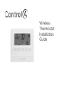
1
Wireless
Thermostat
Installation
Guide
Disclaimer
Control4® makes no representations or warranties with respect to any Control4 hardware, software, or
the contents or use of this publication, and specifically disclaims any express or implied warranties of
merchantability or fitness for any particular purpose. Control4 reserves the right to make changes to any
and all parts of Control4 hardware, software, and this publication at any time, without any obligation to
notify any person or entity of such changes.
Trademarks
©2011 Control4. All rights reserved. All rights reserved. Control4, the Control4 logo, the Control4 iQ logo
and the Control4 certified logo are registered trademarks or trademarks of Control4 Corporation in the
United States and/or other countries. All other names and brands may be claimed as the property of
their respective owners. Pricing and specifications are subject to change without notice.
Control4 Corporation
11734 S. Election Road, Suite 200
Salt Lake City, UT 84020 USA
http://www.control4.com
Wireless Thermostat Installation Guide
Part Number: 21-0170 Rev D, 9/20/2011
Model Number: CCZ-T1-W
Warranty
ii
For complete warranty information, including details on consumer legal rights as well as warranty exclusions, visit www.control4.com/warranty, or refer to the Control4 Wireless Thermostat User Guide on the
Control4 website, Resources > Documentation page at http://www.control4.com/residential/products/
resources/.
Table of Contents
Supported Model ........................................................................................................... 1
Important Safety Instructions ................................................................................... 1
General Description ...................................................................................................... 1
Box Contents ................................................................................................................... 2
Requirements .................................................................................................................. 2
Specifications ................................................................................................................. 3
Pre-Installation Considerations ................................................................................ 4
Installation Instructions................................................................................................ 7
Composer Programming Instructions ......................................................................11
Thermostat Relays ........................................................................................................ 16
Troubleshooting ............................................................................................................ 22
Installing a Bypass Resistor to Enable Power Stealing
on a Wireless Thermostat
............................................................................................................................................... 23
Sample Wiring Configurations ................................................................................. 28
Wiring Connections ...................................................................................................... 29
Regulatory Compliance .............................................................................................. 36
Warranty .......................................................................................................................... 36
iii
Supported Model
CCZ-T1-W
Wireless Thermostat - White
Important Safety Instructions
WARNING! Install in accordance with all national and local electrical codes.
WARNING! This product is not intended for use with line-voltage baseboard heaters.
IMPORTANT! Improper use or installation can cause LOSS/DAMAGE OF PROPERTY.
IMPORTANT! Operate within the limits of this device as specified in this Control4
Wireless Thermostat Installation Guide and the Control4 Wireless Thermostat User
Guide.
IMPORTANT! Using this product in a manner other than outlined in this document
voids your warranty. Further, Control4 is NOT liable for any damage incurred with the
misuse of this product. See the warranty information in the Control4 Wireless Thermostat User Guide or on the Control4 website at www.control4.com/warranty.
General Description
This Control4® Wireless Thermostat enables intelligent HVAC control as part of a Control4 automated system. It uses the ZigBee (802.15.4) wireless networking standard to communicate
with the Control4 system.
The Control4 Wireless Thermostat features a backlit LCD that displays the time, temperature,
date, fan status, hold status, and HVAC operating mode. The front panel allows temperature
setpoint adjustments, HVAC mode change, variable hold options and fan control. The Thermostat can operate as a stand-alone setpoint thermostat if it loses communication Control4
with the system.
1
Box Contents
•
•
•
•
•
•
Wireless Thermostat
CR123A (3V) battery
3 screws (#6 x 1-inch sheet metal screws)
3 plastic wall anchors (#4-6 x 7/8”)
Warranty card
U-shaped terminal jumper wire
•
Power-stealing bypass resistor (270 Ohm)
•
Control4 Wireless Thermostat Installation Guide (this document)
Requirements
•
•
•
•
•
•
2
Pencil (#2 or darker)
Drill with 3/16” drill bit
Small level (optional)
Small flat-blade screwdriver
Phillips screwdriver
Tape for labeling wires
Specifications
Front and Rear View
Figure 1. Faceplate
Figure 2. Rear Plate
Recommended Wiring:
22 AWG (36 ft. max.)
18 AWG (100 ft. max.)
Power Source:
24VAC and 3 volt battery
Power Usage: 1/10W at 24VAC, 50/60 Hz
Set Point Temperature Range: 40˚ F to 90˚ F (5˚ C to 32˚ C)
Operating Temperature: 39˚ F to 131˚ F (4˚ C to 55˚ C)
Storage Temperature:
14˚ F to 185˚ F (-10˚ C to 85˚ C)
Operating Relative Humidity: 0 to 95% (non-condensing)
Dimensions (H x W x D):
4.5” x 3.7” x 1.2”
Communications: ZigBee (IEEE 802.15.4) 2.4 GHz, 15-channel, spread spectrum radio
3
IMPORTANT! The Wireless Thermostat has ‘power stealing’ enabled by default,
however, it is recommended to power the Thermostat with a common wire. If power
stealing is required, verify that your HVAC system supports power stealing prior to
installation in this mode.
Changing this setting is described in Step 14, “Installation Instructions.” For more
information about power stealing, see “Installing a Bypass Resister to Enable Power
Stealing on a Wireless Thermostat” later in this document.
NOTE: The Wireless Thermostat requires power from the HVAC system to maintain
regular communication with the Controller.
Pre-Installation Considerations
Using a Common Wire vs. Power Stealing
The Wireless Thermostat can be configured to operate in a ‘power stealing’ condition when
there is no availability of a dedicated common wire. However, Control4 recommends using a
dedicated common wire whenever possible. With some HVAC systems, power stealing can result in system contention between the Cool and Heat Modes, and will render the HVAC system
inoperable. To aid in resolving this issue, a 270 Ohm 3 Watt Axial resistor is included with the
packaging of each Wireless Thermostat. This resistor is intended to be installed between the
W1 and the Common terminals inside the HVAC system. The resistor, when properly installed,
will lower the risk of causing contention when the Thermostat is actively working in the Cool
mode. Many HVAC systems will not tolerate a power-stealing Thermostat even with the 270
ohm resistor installed properly. In this case, a dedicated common wire is a requirement for
proper functionality.
NOTE: The battery is used for backup purposes only.
4
•
•
New construction, Control4 recommmends these options:
•
Install a common wire.
•
Use a Remote Temperature Sensor in the wall where the Thermostat is located. Run a wire to
the furnace, and then install the Thermostat next to the furnace.
Retrofits, the best solution is to install the Thermostat using an existing common wire. If the box
does not have a common wire, you can:
•
Run a wire from the furnace to the Thermostat location.
•
Use Power Stealing (see Step 14 in “Installation Instructions”).
•
Install a Remote Temperature Sensor in the wall where the Thermostat is located. Run a wire to
the furnace, and install the Thermostat next to the furnace. See “Remote Temperature
Sensor.”
•
Use a separate 24VAC transformer to power the Thermostat.
Supported System Types
This table lists the items that the Thermostat replaces.
Description
CCZ-T1-W
Heat pump (no aux. or emergency heat)
Yes
Heat pump (with aux. or emergency heat)
Yes
Standard heating and cooling system
Yes
Two-stage heat and two-stage cooled
Yes
Standard heat-only systems
Yes
Millivolt heat-only systems - floor or wall furnaces
Yes
Standard central air conditioning
Yes
Gas or oil heat
Yes
Electric furnace
Yes
Hydronic (hot water) - zone heat - 2 wires
Yes
Hydronic (hot water) - zone heat - 3 wires
No
5
Zoned Systems
Control4 supports zoned HVAC systems using a zoning panel. If used, however, a common
wire needs to be installed at the Thermostat. Power stealing is not an option in this case.
Remote Temperature Sensor
A Remote Temperature Sensor allows the Thermostat to get its temperature readings from an
area where the Thermostat is not physically located. Typically, the Thermostat will be located
near the HVAC equipment with only the Remote Temperature Sensor on the wall in the living
area. This creates a much cleaner install. In this case, the Thermostat settings would be controlled using any of the Control4 user interfaces.
A Remote Temperature Sensor is also a good solution in a retrofit when a common wire is
not available and power stealing is not an option. The Thermostat can be mounted in the mechanical room and wired directly to the HVAC equipment. The previously installed Thermostat wiring can then be used to connect the Thermostat to the Remote Temperature Sensor.
6
Installation Instructions
1
2
3
4
Place the Wireless Thermostat in a proper location to ensure its efficiency and to avoid
unnecessary cycling of the furnace or air conditioner.
a. Place the Thermostat (or remote temperature sensor) away from direct sunlight, drafts, exterior doorways, skylights, windows, and exterior walls.
b. Make sure the Thermostat gets strong ZigBee wireless reception: (1) Ensure that
the Thermostat is within 150 feet of another Zigbee device. (2) Avoid having
electrical equipment that may cause interference with the Zigbee signal (such
as cordless telephones that operate on the 2.4 GHz frequency).
Locate and turn OFF the power supply for the HVAC system.
If installing a Thermostat in a new location, refer to “Sample Wiring Configurations” later in
this document for details on wiring the Thermostat, and then go to Step 5.
If replacing an existing thermostat:
a. Check the number and type of wires attached to the old thermostat.
b. When you’re sure the power is shut off, remove the old thermostat from the
wall, but do not disconnect any wires yet.
c. If the old thermostat has a letter identifying each wire, use a piece of tape to
label each wire that corresponds to the letter on the old thermostat, and ensure
they don’t fall back into the wall.
d. Disconnect the old thermostat.
CAUTION! Discard the old thermostat properly or recycle it. Mercury is a
hazardous waste. You MUST dispose of it properly.
7
5 Remove the Control4 Wireless Thermostat from the packaging, and detach the rear plate
from the Thermostat. (Press the release clip at the bottom of the Thermostat to release it,
and then swing the bottom of the Thermostat up.)
6
Thread the wires from the wall through the back of the large rectangu- Figure 3. Opening
lar opening in the new rear plate (see Figure 3), and then position the
new rear plate against the wall to make sure it sits flush.
7
Use a small level or visually check that the rear plate is level; mark the
locations of the three (3) screw holes on the wall (see Figure 4).
8
Remove the rear plate from the wall and drill 3/16-inch mounting holes
at the three (3) screw hole locations you marked previously.
Figure 4. Screw Holes
9
Press the plastic wall anchors (included) into the holes you drilled in
Step 8.
10 Re-thread the wires from the wall through the back of the rear plate of
the new Wireless Thermostat to place the rear plate against the wall
(see Figure 3).
11 Insert the mounting screws (included) into the plastic wall anchors and firmly tighten the
screws.
12 See “Sample Wiring Configurations” later in this document to determine the appropriate
wiring connections for your system configuration.
13 Connect the wires to the screw terminals in the rear plate, matching the labeled wires (see
Step 4d) to the letters on the terminals. The wiring can differ depending on the wires available.
8
14 Select the desired power supply method by enabling or disabling power stealing on the back
of the Thermostat faceplate.
•
•
Disable (recommended). Power stealing is disabled and the Thermostat requires the
HVAC common wire connection for a dedicated power supply.
Enable. The Thermostat steals a small amount of power from the HVAC system transformer to power itself.
15 On the back of the Thermostat faceplate, set the slide switches that sit next to the battery
compartment to match your HVAC system:
a. Set the Mode (bottom) switch to select a system type
Conventional:
Set for conventional heating and cooling systems (default).
Heat Pump:
Select for heat pump system(s).
b. Set the Primary (middle) switch to select Primary stage fan control
Fuel:
The gas or oil furnace equipment controls the fan in heating (default).
Electric:
The Thermostat controls the fan in heating.
c. Set the Secondary (top) switch to select Secondary stage fan control
Fuel:
The gas or oil furnace equipment controls the fan in secondary stage
heating (default).
Electric:
The Thermostat controls the fan in secondary stage heating.
NOTE: If using power stealing, we recommend that you skip Step 16 initially and
continue with Steps 17, 18 and 19 to ensure that the Thermostat is functioning
correctly with power stealing and no battery. After power stealing has been
confirmed as working properly, complete Step 16 (installing battery) and repeat
Steps 17, 18, and 19. The will ensure the battery is only functioning as a backup.
9
16 Install the CR123A (3V) battery (included) in the Thermostat faceplate according to the
polarity labels—POS (+) and NEG (-)—on the Thermostat’s circuit board.
IMPORTANT! Do not install the battery with the wrong polarity.
IMPORTANT! If the battery was already in place and you changed the slide switch
settings, remove the battery and re-install it. This forces the Thermostat to reboot to the
new configuration.
17 Attach the faceplate to the Thermostat’s rear plate:
Figure 5. Faceplace Installation
1. Align the
faceplate with the
rear plate, and push
the straight pins
to the back of the
Thermostat.
2. With the faceplate
slightly above the rear
plate, slide the top edge
of the faceplate onto
the rear plate, engaging
the plastic hooks with
the corresponding holes.
3. Press firmly
on the bottom
center edge of the
faceplace to snap
it. Lock the bottom
hook in place.
18 Turn ON the power supply for the HVAC system.
19 Test the Thermostat in both the Auto and Manual modes to confirm that both the furnace
and air conditioner cycle on and off at the appropriate settings. To operate the Thermostat,
see the Control4 Wireless Thermostat User Guide on the Documentation page of the Control4 website at http://www.control4.com/residential/products/resources/ for Thermostat
programming instructions.
10
Composer Programming Instructions
All advanced programming must be completed by a Control4 Dealer using Composer Pro. To
see what advanced programming options are available as part of the Control4 system, follow
these instructions.
The Wireless Thermostat User Guide is available in the Documentation page at http:
//www.control4.com/residential/products/resources/ which includes basic Thermostat programming instructions using a Touch Screen, On-Screen Navigator, or MyHome app.
Ensure that the Wireless Thermostat is installed as directed in this installation guide.
1
Start Composer Pro and connect to a Director.
2
Click System Design.
3
Add and identify the Control4 Wireless Thermostat driver to the project (see the Composer
Pro User Guide for details).
4
Select the Control4 Wireless Thermostat in the project tree.
5
Click the Properties tab to view the Properties pane (described next).
11
Properties
Fahrenheit or Celsius: Sets the temperature display in Fahrenheit or Celsius.
View/Edit Schedule: Select to access and edit the Thermostat schedule.
Vacation: Select to adjust the vacation heat and cool setpoints.
Use Remote Temperature Sensor: If unchecked (default), the Thermostat will use the on-board
local temperature sensor. Check this box to use an optional Remote Temperature Sensor.
Buttons: Locks and unlocks the physical buttons on the Thermostat.
NOTE: If buttons are disabled, they will be re-enabled when the Thermostat power
cycles. This is a safety mechanism to prevent a Thermostat from becoming
completely inoperable if it were removed from a project while the buttons
were disabled.
Select Apply to… to apply the current properties to the selected Wireless Thermostats.
Advanced Properties
General Setup
Backlight Mode: Sets the backlight preferences. On Button Press lights the backlight for ten
(10) seconds when any Thermostat button is pressed. Always On keeps the backlight constantly
on; not recommended when using power stealing.
Battery: Shows the power source or battery level.
12
Time Format
Date Format: Sets the format preferences for date (MM/DD/YYYY or DD/MM/YYYY).
Time Format: Sets the format preferences for time (12h or 24h).
Sync Time: Synchronizes the time displayed on the Thermostat with the Control4 Controller.
Synchronization automatically occurs daily.
Network
Displays nformational boxes that provide ZigBee networking information (MAC and Firmware
Version).
Select Apply to… to apply the current properties to the selected Wireless Thermostats.
Advanced Device Configuration
Temperature Calibration: Allows calibration of the Thermostat’s reported temperature by +/- 5
degrees. Example: If the Thermostat reads 72 degrees Fahrenheit, and the current temperature
is determined to be 70 degrees Fahrenheit, press the down button two (2) times to lower the
Thermostat reading to 70 degrees Fahrenheit. Select Set Calibration to confirm the change.
NOTE: No changes to calibration should be made within 20 minutes of powering on
the Thermostat. The Thermostat generates a small amount of heat which affects the
calibration. After 20 minutes of continuous operation, this will stabilize allowing
proper calibration.
Heating Cutoff Point: Sets the temperature for the heating system to turn off past the setpoint.
To adjust, use the up and down arrows, and then press Set Heat Cutoff to confirm the change.
Example: If the Heat Point is set to 68 degrees Fahrenheit, and the Heating Cutoff Point is set
13
to 2 degrees, the heating system will engage until reaching 70 degrees Fahrenheit.
Cooling Cutoff Point: Sets the temperature for the cooling system to turn off past the setpoint.
To adjust, use the up and down arrows and press Set Cool Cutoff to confirm the change.
Example: If the Cool Point is set to 68 degrees Fahrenheit, and the Cooling Cutoff Point is set to
2 degrees, the cooling system will engage until reaching 66 degrees Fahrenheit.
Stage Minimum Off Time (Minutes): Sets the minimum time heating or cooling will remain off
before initiating again. To adjust, use the up and down arrows. The setting takes affect when
you close this box. Example: If while cooling or heating, the temperature does not reach the
designated Cutoff Point before the Maximum Run Time is reached, the cooling system will shut
off and not initiate cooling again until the Minimum Off Time is reached.
NOTE: Some HVAC systems automatically enforce a minimum off time. In this case,
the heating or cooling will remain off for the higher of the two settings
(Thermostat or HVAC system).
Stage Configuration (Heat 1-2, Cool 1-2, Auxiliary Heat, Emergency Heat)
The following settings take affect when you close the page.
NOTE: Auxiliary heat and emergency heat are for heat pump systems only.
Delta: Sets how many degrees the current temperature will reach beyond the temperature set
point before the stage engages. To adjust, use the up and down arrows. Example: If the Heat
Set Point is 70 degrees Fahrenheit, and the delta is 2 degrees, the heat stage will engage when
the temperature reaches 68 degrees Fahrenheit.
14
NOTE: For multistage systems, the deltas for the first and second stages are cumulative. If the first stage delta is set at 2 degrees, and the second stage delta is set at 2
degrees, the second stage will not engage until the current temperature has passed
the stage setpoint by 4 degrees. However, the Auxiliary Heat and Emergency Heat
deltas are NOT cumulative.
Minimum Run Time (Minutes): Sets the minimum time the heating or cooling will run before
shutting off. To adjust, use the up and down arrows. Example: If while cooling or heating, the
temperature reaches the designated Cutoff Point before the Minimum Run Time is reached, the
system will not shut off until the Minimum Run Time is reached. Also, if heat or cool is engaged
and shut off manually, the system will not shut off until the Minimum Run Time is reached.
NOTE: Some HVAC systems have built-in Minimum Run Times that may be greater than
that set on the Thermostat.
Maximum Run Time: Sets the maximum time heating or cooling will run before turning off. To
adjust, use the up and down arrows. Example: If cooling or heating is engaged, but does not
reach the Cutoff Point before the Maximum Run Time is reached, the cooling system will turn
off.
NOTE: The Maximum and Minimum Run Times are not per stage, but for cooling and
heating run times regardless of first or second stage transitions.
Auxiliary Stage
Stage Delay (Minutes): Sets the allotted time the main heat pump system will run without
reaching the Heat Set Point before the auxiliary stage engages. To adjust (in minutes), use the
up and down arrows.
NOTE: If set to the maximum time, the auxiliary system will be disabled and never
engage.
Stage Cutoff Delay (Seconds): Sets the time delay before the main heat pump cuts off, leaving
the auxiliary heating stage to run on its own. To adjust (in seconds), use up and down arrows.
15
NOTE: If set to the maximum time, the main heat pump stage and the auxiliary heat
stage will run together indefinitely.
Thermostat Relays
This section shows the relays that are engaged during heating and cooling for the various Wireless Thermostat configurations.
Conventional Stage: Heating
Primary Fan (Fuel), Secondary Fan (Fuel)
Stage
Y1
Y2
W1
1st Stage
*
2nd Stage
*
W2
O
B
G
O
B
G
*
Primary Fan (Electric), Secondary Fan (Fuel)
Stage
Y1
Y2
W1
1st Stage
*
2nd Stage
*
W2
*
*
*
Primary Fan (Fuel), Secondary Fan (Electric)
Stage
Y1
Y2
W1
1st Stage
*
2nd Stage
*
16
W2
*
O
B
G
*
Primary Fan (Electric), Secondary Fan (Electric)
Stage
Y1
Y2
W1
1st Stage
*
2nd Stage
*
•
•
W2
O
B
G
*
*
*
The switch in the fuel position causes the Thermostat to deactivate the “G” fan relay, allowing
the furnace to control the fan.
The switch in the electric position causes the Thermostat to activate the “G” fan relay, allowing
the Thermostat to control the fan.
Conventional Stage: Cooling
Primary Fan (Fuel), Secondary Fan (Fuel)
Stage
Y1
1st Stage
*
2nd Stage
*
Y2
W1
W2
O
B
G
*
*
*
Primary Fan (Electric), Secondary Fan (Fuel)
Stage
Y1
1st Stage
*
2nd Stage
*
Y2
W1
W2
O
B
G
*
*
*
17
Primary Fan (Fuel), Secondary Fan (Electric)
Stage
Y1
1st Stage
*
2nd Stage
*
Y2
W1
W2
O
B
G
*
*
*
Primary Fan (Electric), Secondary Fan (Electric)
Stage
Y1
1st Stage
*
2nd Stage
*
Y2
W1
W2
O
B
G
*
*
*
Heat Pump: Heating
Primary Fan (Fuel), Secondary Fan (Fuel)
Stage
Y1
Y2
1st Stage
*
2nd Stage
*
*
3rd Stage (Before
Aux Stage Delay)
*
*
(If Stage 2
is engaged)
3rd Stage (After
Aux Cutoff Delay)
E Heat (Stage 1)
18
W1
W2
*
*
*
O
B
G
*
*
*
*
*
*
Primary Fan (Electric), Secondary Fan (Fuel)
Stage
Y1
Y2
1st Stage
*
2nd Stage
*
*
3rd Stage (Before Aux Stage
Delay)
*
*
Auxiliary Stage (After Aux
Stage Delay)
W1
W2
O
*
B
G
*
*
*
*
*
*
*
E-Heat (Stage 1)
*
*
Primary Fan (Fuel), Secondary Fan (Electric)
Stage
Y1
Y2
1st Stage
*
2nd Stage
*
*
3rd Stage (Before Aux Stage
Delay)
*
*
3rd Stage (After Aux Cutoff
Delay)
E-Heat (Stage 1)
W1
W2
*
O
B
G
*
*
*
*
*
*
*
*
*
19
Primary Fan (Electric), Secondary Fan (Electric)
Stage
Y1
Y2
1st Stage
*
2nd Stage
*
*
3rd Stage
*
*
E-Heat
(Stage 1)
•
•
•
•
•
•
20
W1
W2
*
*
O
B
G
*
*
*
*
*
*
*
*
The Primary Fan switch selects the operating mode for auxiliary heat.
The switch in the electric position indicates that the heat pump is connected to an air handler
system, and the Thermostat will control the ‘G’ fan relay. ‘Y1’ and ‘Y2’ will remain energized
during 3rd stage heating.
The switch in the fuel position indicates the heat pump is connected to a furnace system
with the heat pump heat exchanger in-line (downstream) from the furnace hot air. In this
case, ‘Y1’ and ‘Y2’ will de-energize after a configurable auxiliary heat cutoff delay and remain
de-energized during the remainder of the 3rd stage heat cycle.
Emergency heat can only be activated by pressing the front panel control mode button.
Emergency heat is only available in a heat pump system, and will always activate relay ‘W2’
and de-energize ‘Y1’ and ‘Y2.’
The Secondary Fan switch selects the operating mode for Emergency heat.
The switch in the electric position causes the Thermostat to activate the ‘G’ fan relay.
Heat Pump: Cooling
Primary Fan (Fuel), Secondary Fan (Fuel)
Stage
Y1
1st Stage
*
2nd Stage
*
Y2
W1
W2
*
O
B
G
*
*
*
*
Primary Fan (Electric), Secondary Fan (Fuel)
Stage
Y1
1st Stage
*
2nd Stage
*
Y2
W1
W2
*
O
B
G
*
*
*
*
Primary Fan (Fuel), Secondary Fan (Electric)
Stage
Y1
1st Stage
*
2nd Stage
*
Y2
W1
W2
*
O
B
G
*
*
*
*
Primary Fan (Electric), Secondary Fan (Electric)
Stage
Y1
1st Stage
*
2nd Stage
*
Y2
*
W1
W2
O
B
G
*
*
*
*
21
Additional Information
Traditionally, while in Heat Pump mode, relay ‘O’ will always call for COOL and relay ‘B’ will
always call for Heat. Some HVAC systems, however, have O/B combined. Depending on the
state of the reversing valve this can be changed so ‘B’ becomes COOL and ‘O’ becomes HEAT.
Troubleshooting
If the Thermostat is not working:
1.
2.
3.
4.
Ensure that the HVAC system is not turned OFF.
Check for proper wiring (see “Sample Wiring Configurations”).
Using a volt meter, test for correct voltage to power the Thermostat between terminals RH
and TS/C (24v dependent on HVAC system transformer).
After installing the Thermostat, press the buttons on the Thermostat using the following
sequence to reboot it: left button 9 times, middle button 4 times, right button 9 times. The
Thermostat must be rebooted after changing switches so that it recognizes the changes.
For help on the installation or operation of the Wireless Thermostat, email support@control4.
com, check the Technical Support page at http: //www.control4.com/residential/products/
resources/, or call the Control4 Technical Support Center. Please provide your exact model
number.
22
Installing a Bypass Resistor to Enable Power Stealing on a
Wireless Thermostat
Although Control4 recommends using a common wire to provide power to the Thermostat, the
Wireless Thermostat is capable of power stealing. This should only be done when using a common wire is not feasible.
Not all HVAC configurations reliably permit power stealing. If your HVAC uses an integrated digital control panel as part of a zoning system, or it is built into the heating or cooling equipment,
it is more likely to encounter difficulties interfacing with a power stealing Thermostat. Installing
the bypass resistor (included) can help minimize the effects of power stealing on the HVAC
system. Some HVAC configurations, however, do not require the bypass resistor to reliability use
power stealing. Other HVAC systems may not be able to use power stealing reliably even with
the bypass resistor installed.
Bypass Resistor Instructions
Included in the packaging of each Control4 Wireless Thermostat is a 270 Ohm 3W resistor. Following the steps below, connect the resistor to the HVAC system to provide a bypass path from
the heat relay circuit to the common side of the 24V HVAC transformer:
1
Locate the supplied 270 Ohm Resistor (see Figure 6) which is included in the Thermostat
packaging with the Thermostat battery, wall anchors and screws).
23
Figure 6. Bypass Resistor
2
Access the 24V transformer and integrated control panel on the HVAC system. This typically
requires removing the front panel of the furnace. Remember to turn OFF the power to the
HVAC system before accessing the transformer.
3
Install the resistor on the HVAC system, not on the Thermostat. Wire the resistor from the
Heat Relay Terminal (W or W1) to the common side of the 24Volt HVAC system transformer.
Figure 7 shows the wiring diagram of a typical single-stage HVAC system with the resistor in
place.
24
Figure 7. Gas/Electric Single Stage
25
4
Loosen the screw on the heat terminal (typically marked ‘W’ or ‘W1’) and secure
one end of the resistor in the HVAC system’s Heat Relay Terminal by tightening the
terminal screw.
5
Connect the other end of the resistor to the 24V common return path. Two completed wiring examples are shown below.
Example 1. The first example (Figure 8) shows an HVAC system with a dedicated
24V Common screw terminal on the control board. The resistor simply spans between the Heat Relay Terminal (W) and the Common Terminal, providing a bypass
for some of the current that would otherwise pass through the heat relay circuit.
Figure 8. HVAC with Common Screw Terminal
Common Terminal
Bypass Resistor
26
Heat Relay
Terminal (W)
Example 2. This second example (Figure 9) shows a control board that does not provide a
common wire screw terminal. In this example, an additional length of wire was added to the
resistor which allowed it to connect from the ‘W’ terminal to the connector for the 24V common that connects from the HVAC transformer to the control board.
Figure 9. HVAC without a Common Screw Terminal
Bypass Resistor
24V Common
Wire Extension
Heat Relay
Terminal (W)
6
When the bypass resistor is in place, you should re-assemble any covers or housings that
were removed to access the transformer and control panel (often, safety switches prohibit
the HVAC equipment from running until all covers are in place).
7
Restore power to the HVAC system and test that both heating and cooling are functioning
correctly with the resistor in place.
27
Sample Wiring Configurations
The next several pages provide sample Thermostat connections and configurations for
your reference.
WARNING! Do not install LINE VOLTAGE wires to a LOW VOLTAGE wire.
IMPORTANT! When utilizing power stealing, Control4 recommends installing the
included 270 Ohm bypass resistor on the HVAC system to minimize any potential
side effects. See the previous section “Installing a Bypass Resistor to Enable Power
Stealing on a Wireless Thermostat.”
IMPORTANT! Do not install any Remote Temperature Sensors to the TS terminals
other than supported external temperature sensors (Flush Mount Remote Temperature Sensor, Aprilaire™ Model 8051 or Duct/Outdoor Remote Temperature Sensor,
Aprilaire Model 8052, etc.). For installation instructions, see your Aprilaire documentation.
IMPORTANT! Install the U-shaped Terminal jumper wire between RC and RH for a
single stage system.
28
Wiring Connections
To see which relays are triggered when certain modes of the Thermostat are called
for, see “Additional Information” and “Thermostat Relays” described previously.
Terminal
Description
RH
24VAC power for heating—connect to low voltage heating system transformer. (See Note 1 below.)
RC
24VAC power for cooling—connect to low voltage cooling system transformer. (See Note 1 below.)
B
Heat Pump—heat changeover valve
G
Fan Relay
Y1
Conventional—air conditioner compressor
Heat Pump—primary stage relay
Y2
Conventional—2nd stage compressor
Heat Pump—2nd stage relay
W1
Conventional—heat relay
Heat Pump—auxiliary heat relay
W2
Conventional—2nd stage heat relay
Heat Pump—emergency heat line
O
Heat Pump—cool changeover valve
TS
Remote sensor (optional accessory)
TS/C
Remote sensor (optional accessory)
NOTES:
1.
Install the U-shaped Terminal jumper wire provided between RC and RH for a single stage system.
2.
When connecting the common wire, ensure that power stealing is disabled as described in “Installation
Instructions,” Step 14.
3.
Refer to the table in Step 14 of “Installation Instructions” for information about switch settings.
29
Figure 10. Conventional, Single Stage Wiring
30
Figure 11. Conventional, Dual Stage Wiring
31
Figure 12. Heat Pump, Single Stage Wiring
32
Figure 13. Heat Pump with Electric Auxilliary Heat, Dual Stage Wiring
33
Figure 14. Millivolt Heat, Conventional Cool, Single Stage Wiring
34
Figure 15. Heat Pump with Electric Auxilliary, Dual Stage, Dual Transformer Wiring
35
Regulatory Compliance
To review regulatory information for your particular Control4 products, see the information located on the
Control4 website at: http://www.control4.com/regulatory/
Warranty
Limited 2-year warranty. Refer to http://www.control4.com/warranty.
36