1
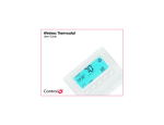
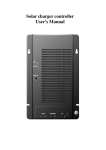
6
Specifications
Front and Rear View
Face Plate
Rear Plate
7
Wireless
Thermostat
Installation
Guide
8
The specifications are described as follows.
Recommended Wiring:
Power Source:
Power Usage:
Set Point Temperature Range:
Operating Temperature:
Storage Temperature:
Operating Relative Humidity:
Dimensions (HxWxD):
Communications:
Supported Models and Requirements
CCZ-T1-W
Wireless Thermostat - White
IMPORTANT! By default, this thermostat is configured to utilize “power
stealing”. Please verify that your HVAC system supports power stealing
prior to installation in this mode. Changing this setting is described in
Step 14.
Important Safety Instructions
NOTE: The Wireless Thermostat requires power from the HVAC
system to maintain regular communication with the controller. The
battery is intended to provide supplemental or backup power only.
WARNING! Install in accordance with all national and local electrical
codes.
WARNING! This product is not intended for use with line-voltage
baseboard heaters.
IMPORTANT! Improper use or installation can cause LOSS/DAMAGE
OF PROPERTY.
IMPORTANT! Operate within limits of this device as specified in this
Control4 Wireless Thermostat Installation Guide and the Control4
Wireless Thermostat User Guide.
1
Place the thermostat in a good location (see items below) to ensure its
efficiency and avoid unnecessary cycling of the furnace or air
conditioner.
•
•
General Description
This thermostat enables intelligent HVAC control as part of a Control4
automated system. It uses the ZigBee (802.15.4) wireless networking standard
to communicate with the Control4 system.
The Control4 Thermostat features a backlit LCD display showing time,
temperature, date, fan status, hold status, and HVAC operating mode. The
front panel allows for temperature setpoint adjustment, HVAC mode change,
variable hold options and fan control. It can also operate as a stand-alone setpoint thermometer if it loses communication Control4 with the system.
2
3
Thermostat
CR123A (3V) Battery
3 Screws (#6 x 1 inch sheet metal screws)
3 Plastic wall anchors (#4-6 x 7/8”)
Product Registration Card
U-shaped Terminal Jumper Wire
•
Power Stealing bypass resistor (270 Ohm)
•
•
Control4 Wireless Thermostat Installation Guide
Control 4 Wireless Thermostat User Guide
Pencil (#2 or darker)
Drill with 3/16” drill bit
Small Level (optional)
Small flat-blade
screwdriver
Phillips screwdriver
Tape for labeling wires
12
13
14
4
15
Connect the wires to the screw terminals in the rear plate, matching the
labeled wires (Step c.) to the letters on the terminals. The wiring can
differ depending upon the wires available.
Select the desired power supply method by enabling or disabling Power
Stealing on the back of the thermostat faceplate.
Enable (default) = The thermostat steals a small amount of power
from the HVAC system transformer to power itself.
Disable = Power Stealing is disabled and the thermostat requires the
HVAC “common wire” connection for a dedicated power supply.
On the back of the thermostat faceplate, set the slide switches that sit
next to the battery compartment to match your system:
b.
Set the Mode (bottom) switch to select a system type.
Electric:
c.
d.
cover from its rear plate, but do not disconnect any wires yet.
Unscrew and remove the old thermostat's rear plate from the wall;
If the old thermostat has a letter identifying each wire, use a piece of tape to
label each wire that corresponds to the letter on the old thermostat and ensure
they don’t fall back into the wall.
Disconnect the old thermostat.
CAUTION! Discard the old thermostat properly or recycle it. Mercury is
a hazardous waste. You MUST dispose of it properly.
Detach the rear plate from the Control4 Wireless Thermostat. (Press the
release clip at the bottom of the thermostat to release it and swing the
bottom up.)
Select for Heat Pump systems
Gas or oil furnace equipment controls fan in heating
(default)
Thermostat controls fan in heating
Set the Secondary (top) switch to select secondary stage fan control.
Fuel:
Electric:
If replacing an existing thermostat:
Set for Conventional heating and cooling systems (default)
Set the Primary (middle) switch to select primary stage fan control.
Fuel:
Test the thermostat in both the auto and manual modes to confirm that
the furnace and air conditioner cycle on and off at the appropriate
settings. To operate it, see Control4 Wireless Thermostat User Guide.
As part of a Control4 system, the thermostat can follow a schedule with up to
six different set points per day. You can also control the thermostat using the
Wireless Touch Screen, the On-Screen Navigator (on your TV), the Mini Touch
Screen, or the LCD Keypad. (See the Composer Online Help for programming
instructions, and see the Control4 Wireless Thermostat User Guide for
programming instructions using one of the navigation devices).
If thermostat is not working:
See “Sample Wiring Configurations” on page 2 to determine the
appropriate wiring connections for your system configuration.
Heat Pump:
Turn ON power supply for the HVAC system.
Troubleshooting
Insert the mounting screws (included with the product) into the plastic
wall anchors and firmly tighten the screws.
Conventional:
16
Figure 2
Re-thread the wires from the wall through
the rear plate of the new thermostat to
place the rear plate against the wall (Figure 1).
a.
18
19
Programming Instructions
Press the plastic wall anchors (included
with the product) into the holes you drilled
in Step 8.
•
Gas or oil furnace equipment controls fan in secondary
stage heating (default)
Thermostat controls fan in secondary stage heating
Install the CR123A (3V) battery (included with the product) in the
Control4 thermostat faceplate according to the polarity labels, POS (+)
and NEG (-), on the thermostat circuit board.
IMPORTANT! Do not install the battery in the wrong polarity.
a. Check the number and type of wires attached to your old unit.
b. When you are sure the power has been shut off, remove the old thermostat’s
5
Remove the rear plate from the wall and
drill 3/16-inch-mounting holes at the three
screw hole locations you marked
previously.
•
Place the thermostat and optional external thermostat sensors
away from direct sunlight, drafts, exterior doorways, skylights,
windows, and exterior walls.
Make sure the thermostat gets good ZigBee wireless reception:
(1) Ensure that the thermostat is within 150 feet of another
Zigbee device. (2) Avoid having electrical equipment that may
cause interference with the Zigbee signal (such as cordless
telephones that operate on the 2.4 GHz frequency).
If installing a thermostat in a new location, refer to “Sample Wiring
Configurations” on page 2 for details on wiring the thermostat and then
skip to Step 5.
Requirements
•
•
•
•
•
•
11
Figure 1
Use a small level or visually check that the
rear plate is level, then mark the locations
of the three screw holes on the wall (Figure
2).
Locate and turn OFF the power supply for the HVAC system.
c.
•
•
•
•
•
•
10
Installation
IMPORTANT! Using this product in a manner other than outlined in this
document voids your warranty. Further, Control4 is NOT liable for any
damage incurred with the misuse of this product. See the warranty
information in the Control4 Wireless Thermostat User Guide.
What is in the Box
22 AWG (36 ft. max)
18 AWG (100 ft. max)
24 Volt and 3 Volt battery
1/10 W at 24 VAC, 50/60 Hz
40 F to 90 F (5 C to 32 C)
39 F to 131 F (4 C to 55 C)
14 F to 185 F (-10 C to 85 C)
0 to 95% (non-condensing)
4.5 x 3.7 x 1.2 inches
ZigBee (IEEE 802.15.4) 2.4 GHz, 15-channel,
spread spectrum radio
9
Thread the wires from the wall through the
large rectangular opening in the new rear
plate (Figure 1), then position the new rear
plate against the wall to make sure it sits
flush.
•
•
Ensure HVAC system is not turned OFF.
Check for proper wiring. (See “Sample Wiring Configurations” on page 2.)
For help on the installation or operation of this product, email or call the
Control4 Technical Support Center. Please provide your exact model number.
Contact [email protected] or see the web site www.control4.com.
Regulatory Compliance
This product complies with standards established by the following regulatory bodies:
Federal Communications Commission (FCC) and Industry Canada
FCC
FCC ID: R33CCZT11. This device complies with Part 15 of the FCC Rules. Operation is
subject to the following two conditions: (1) this device may not cause harmful interference,
and (2) this device must accept any interference received, including interference that may
cause undesired operation.
This equipment has been tested and found to comply with the limits for a Class B digital
device, pursuant to Part 15 of the FCC Rules. These limits are designed to provide
reasonable protection against harmful interference in a residential installation. This
equipment generates, uses, and can radiate radio frequency energy and, if not installed
and used in accordance with the instructions, may cause harmful interference to radio
communications. However, there is no guarantee that interference will not occur in a
particular installation. If this equipment does cause harmful interference to radio or
television reception, which can be determined by turning the equipment off and on, the
user is encouraged to try to correct the interference by one or more of the following
measures:
•
•
•
•
Reorient or relocate the receiving antenna.
Increase the separation between the equipment and receiver.
Connect the equipment into an outlet on a circuit different from that to which the receiver is
connected.
Consult the dealer or an experienced radio/TV technician for help.
IMPORTANT! Changes or modifications not expressly approved by Control4 void the
user’s authority to operate the equipment.
Industry Canada
This Class B digital apparatus complies with Canada ICES-003.
Cet appareil numérique de la classe B est conforme à la norme NMB-003 du Canada.
IMPORTANT! If the battery was in place and you changed slide switch
settings, remove the battery and reinstall it. This forces the thermostat
to reboot with the new configuration.
17
Install the faceplate to the thermostat rear plate. To do this:
1. Align the
faceplate with
the rear plate
and push the
straight pins to
the back of the
thermostat.
2. With the faceplate
slightly above the rear
plate, slide the top edge of
the faceplate onto the rear
plate, engaging the plastic
hooks with the
corresponding holes.
3. Press firmly on
the bottom center
edge of the
faceplace to snap
and lock the
bottom hook in
place.
Recycling
For information on recycling, please go to wwww.control4.com/
recycling
Sample Wiring Configurations
WARNING! Do not install LINE VOLTAGE wires to a LOW
VOLTAGE wire.
IMPORTANT! When utilizing power stealing, we recommend
installing the included 270 Ohm bypass resistor on the HVAC
system to minimize any potential side-effects. For additional
information on power stealing and installing the bypass resistor, visit
control4.com.
IMPORTANT! Do not install any REMOTE TEMPERATURE
SENSORS to the TS terminals other than supported external
temperature sensors (Flush Mount Remote Temperature Sensor,
Aprilaire™ Model 8051; or Duct/Outdoor Remote Temperature
Sensor, Aprilaire Model 8052). For installation instructions, see
Aprilaire documentation.
IMPORTANT! Install the U-shaped Terminal jumper wire between
RC and RH for a single stage system.
Wiring Connections
Terminal
Description
RH
24VAC power for heating — connect to low voltage heating system
transformer. (See Note 1 below.)
RC
24VAC power for cooling — connect to low voltage cooling system
transformer. (See Note 1 below.)
B
Conventional — heat damper control
Heat Pump — heat changeover valve
G
Fan Relay
Y1
Conventional — air conditioner compressor
Heat Pump — primary stage relay
Y2
Conventional — 2nd stage compressor
Heat Pump — 2nd stage relay
W1
Conventional — heat relay
Heat Pump - auxiliary heat relay
W2
Conventional — 2nd stage heat relay
Heat Pump — not used
O
Conventional — cool damper control
Heat Pump — cool changeover valve
TS
Remote sensor (optional accessory)
TS/C
Remote sensor (optional accessory)
Common wire return for dedicated power supply.
Note 1: Install the U-shaped Terminal jumper wire provided between RC and RH for
a single stage system.
Note 2: When connecting the common wire, ensure that power stealing is disabled
as described in step 14.
Warranty
For complete warranty information, including details on consumer legal rights as well as warranty
exclusions, visit www.control4.com/warranty.
About this Document
United States Patents Pending. Copyright © 2004-2006 Control4 Corporation. Control4 and the
Control4 logo are registered trademarks of Control4 Corporation. All trademarks are properties of
their respective owners.
Part Number: 21-0170 Rev C (3)
Control4 Wireless Thermostat Installation Guide
2