1
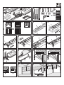
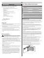
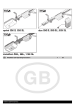
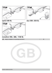
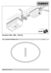
marathon 550 SL, 800 SL, 1100 SL
Installation and Operating Instructions
10514V000-462001-0-OCE-Rev.A
Page 17 - 33
GB
• Only install the drive mechanism to correctly aligned and weightbalanced doors. An incorrectly aligned door could cause serious injury or
damage to the drive mechanism.
Contents
Foreword
Symbols
Safety Instructions
Normal Use
Technical Data
EU Manufacturers' Declaration
Rating Plate
Installation
marathon SL Control Unit
Radio Receiver 868.8 MHz
Initial Operation
Additional Functions
Operation and Handling
Accessories
Maintenance and Care
Disassembly
Warranty and After-sales Service
Troubleshooting
17
17
17
18
18
18
18
19
22
24
25
26
28
29
30
31
31
31
• Doors that operate automatically by means of the drive mechanism must
comply with the following standards: EN 12604, EN 12605.
• Installation, connection and initial operation of the drive mechanism may
only be carried out by qualified specialists.
• Always disconnect the drive mechanism from the power supply before
carrying out any work.
• Only use the manufacturer's original spare parts, accessories and
fastening materials.
Storage Tips
• The drive mechanism may only be stored indoors, in a dry, sealed
environment at an ambient temperature of between -20°C and +50°C.
• The drive mechanism should be stored horizontally.
Operation-related Safety Instructions
• The drive mechanism may only be operated if a risk-free force tolerance
has been set. The force tolerance must be set as low as is required to
ensure that the door's closing force does not constitute a danger
(see 'Force Setting' section).
Foreword
• Keep your hands clear of any moving door or any moving parts.
• Keep children, disabled persons and animals away from the door.
Our new garage door drive mechanisms 'marathon 550 SL' 'marathon 800
SL' and 'marathon 1100 SL' combine reliability with innovation. The new
'marathon 550 SL' range replaces the current 'marathon S 550 N',
marathon S 800 N' and 'marathon S 1100 N' models whilst offering new
functions and connecting options (e.g. soft run, 2nd button, interface for
TorMinal, etc.).
As the connection set-up of the 'marathon 550 SL' control unit is not
compatible with the current 'marathon' models, the latter can only be
upgraded to 'marathon SL' models by replacing the control unit as a whole
or converting the control unit housing.
Furthermore, the new drive is supplied with our new radio control system
based on a frequency of 868.8 MHz, which offers enhanced security
standards. The system features rolling code technology, where the code is
changed for each new radio command, thus offering optimum security.
• Only drive into and out of the garage when the door is fully opened.
• Closing edges and workings of the door pose risk of injury.
Safety Instructions for Radio-controlled
Operation
• The radio remote control may only be used for equipment and systems in
which defective remote operation of the transmitter or receiver does not
constitute a risk to people, animals or objects, or in cases where this risk
is eliminated by means of additional safety facilities.
• Use of the radio remote control in conjunction with equipment or systems
subject to an enhanced risk of accident (e.g. crane systems) is prohibited!
• To ensure safe operation, local safety regulations relevant to the
equipment concerned must be observed! Information regarding this can
be obtained from electricity suppliers, the VDE and employers' liability
insurance associations.
Symbols
• The user must be made aware of the fact that the remote control of
equipment with accident risk potential may only occur, if at all, when the
equipment concerned is clearly visible.
Indicates a potential risk. Failure to follow instructions may
result in serious injuries.
• Radio remote control may only be used if movement of the door can be
supervised and there are no persons or objects in the area of movement.
Information, useful advice.
A.1
(1)
• Store the manual remote control such that there is no risk of it being
accidentally operated by, for instance, children or animals.
Refers to the relevant illustration in the introduction or main
text.
Safety Instructions
General Safety Instructions
• These Installation and Operating Instructions (MBA) must be read,
understood and observed by the person installing, operating or
maintaining the drive mechanism.
• The manufacturer accepts no liability for damage or malfunctions caused
by failure to follow theses Operating Instructions.
• Make sure that these Operating Instructions are readily accessible in the
garage.
• Observe and comply with the locally applicable accident prevention
regulations and EC standards.
17
GB
Safety Instructions for Authorised
Radio-controlled Operation
Technical Data
marathon
• The operator of this radio-controlled equipment is in no way protected
from interference from other telecommunications systems and facilities
(e.g. other radio-controlled equipment that is licensed to operate at the
same frequency range). Should serious interference be encountered,
please contact your nearest telecommunications office with interference
measuring facilities (radio signal localisation)!
550 SL
800 SL
230
230
230
50/60
50/60
50/60
Hz
Maximum traction and
pressure force:
550
800
1100
N
Rated traction:
165
240
330
N
Rated current consumption:
0,7
0,8
0,9
A
Rated power consumption:
150
160
190
W
Maximum speed:
180
130
130
mm/s
Power consumption (stand-by):
~2
~2
~2
W
Rated voltage:
Rated frequency:
• Under no circumstances may this radio-controlled equipment be linked to
any other telecommunications system without the express authorisation
of the relevant licensing authorities.
• Do not use the manually-operated remote control near locations or
installations that are susceptible to radio interference
(airports, hospitals).
Operating temp. Range:
-20 - +50
Weight:
Normal Use
1100 SL
-20 - +50 -20 - +50
18
18,5
19
V/AC
°C
kg
Workplace-specific emission value < 75 dBA - drive only
Important to note!
If the drive mechanism is installed by a company qualified to do
so, the company concerned must carry out an acceptance/
transfer test and fit a rating plate to the door. A copy of the test
protocol and the drive mechanism's Installation and Operation
Instructions should be kept by the operator.
EU Manufacturers' Declaration
Messrs.
SOMMER Antriebs- und Funktechnik GmbH
Hans-Böckler-Straße 21-27
D-73230 Kirchheim/Teck
• Doors that operate automatically by means of the drive mechanism must
comply with the following standards: EN 12604, EN 12605.
• The drive mechanism is intended for the exclusive purpose of opening
and closing the doors. Any other use does not constitute normal use.
hereby declares that the machine component designated below is intended
to be fitted into a gate mechanism and that commissioning is prohibited
until it has been ascertained that the installation in which this equipment is
to be fitted complies with all the relevant provisions of the applicable EU
directives.
• The manufacturer accepts no liability for damage resulting from use other
than normal use. The user accepts sole responsibility for any risk thereby
incurred.
• The drive mechanism may only be used if it is in a technically perfect
condition and in compliance with these Installation and Operating
Instructions (MBA) particularly regarding correct and responsible usage.
Designation of machine component:
- marathon 550 SL garage door drive mechanism
- marathon 800 SL garage door drive mechanism
- marathon 1100 SL garage door drive mechanism
• Any defects that may impair the safe operation of the equipment should
be eliminated without delay.
The relevant directives and standards are as follows:
- Machine Directive 98/37/EG
- Low Voltage Directive 73/23/EEC, Machine Directive 89/392/EEC
- EU Electromagnetic Compatibility Directive 89/336/EEC
• The gate wings must be stable and warp-proof, i.e. they should not bend
or warp during opening or closing operations.
• The drive mechanism is unable to compensate for any defects in the
door or for its incorrect installation.
• Only use the drive mechanism in a dry, indoor environment where there
is no risk of explosion.
Kirchheim, 01.07.2001
Uwe Sommer
Managing Director
• The ambient temperature for drive mechanism operation and storage is
between -20°C and +50°C. Should extreme weather conditions prevail,
consult your local stockist for advice.
Maximum door dimensions:
550 SL
800 SL
1100 SL
3500 mm
6000 mm
8000 mm
- max. height of canopy doors:
2600 mm
2600 mm
2600 mm
- max. height of vertical sectional doors:
2350 mm
2350 mm
2350 mm
- max. width:
Rating Plate
The rating plate is located on the cover of the control unit housing.
The following is an example of a rating plate:
With taller doors, corresponding rail extensions need to be installed - see
'Accessories' section.
- duty cycle:
40 %
40 %
Model :
marathon 550 SL, FM 868 MHz
Manufacturer:
SOMMER Antriebs- und Funktechnik GmbH
D-73230 Kirchheim/Teck
40 %
Any other or non-compliant usage is deemed to be incorrect. The
manufacturer is not liable for any damage occurring as a result. The user is
responsible in such cases. Any warranty entitlement lapses.
Article no.:
4200V000
Year built:
07/2001
Serial no.:
?
230V~ 50/60 Hz
150W/0.7A at 165N rated traction; max. 550N traction and pressure force
Operating temp. Range -20°C - +50°C
After-run distance <30mm; ED: 40% S3
Nur für trockene Räume
Use only in dry rooms
Seulement pour les chamdres séches
18
GB
Door Types and Special Accessories*
Installation
1
* Accessories are not included in the delivery specification.
Supplied Parts and Components
Door type
C-rails, chain with bogie unit and drive shaft
Control unit in housing, push-button cable, mains cable
Connecting element
Lintel fitting
Ceiling mounting
Installation accessories in bag comprising:
1 push-button
5 hexagon-head, self-tapping screws 6.5 x 19
4 wood screws 8 x 60
4 plugs S10
4 plain washers 8.4
Installation and Operating Instructions
2
Accessories
3
Up-and over,
Tracked door
No special accessories required
4
Vertical sectional door with
single runner rail
Vertical sectional door
fitting with boomerang *
4
Vertical sectional door with
double runner rail
Vertical sectional door
fitting without boomerang *
4
Shutter-type door
No accessories required
5
Canopy and non-protuding door
Bow arm convertor system*
6
Swing door
Swing-door fitting *
7
Side-opening sectional door
Please consult specialist retailer
Tools Required
Installation Tips
See Figure
• Check that all the parts have been supplied before you start installation
work in order to save time and unnecessary work if a part is missing.
• The drive mechanism can be installed to one side of the door if it cannot
be installed at the centre. It is important to note that the door does not
bend as a result and jam in the guide rails.
Check
Open and close the door several times by hand holding it at the point
where you intend fitting the drive mechanism. If the door can be moved
in this way without difficulty (in compliance with the above forces), then
the drive mechanism can be fitted at this point.
Safety Tips
• Installation, connection and initial operation of the drive mechanism may
only be carried out by qualified specialists.
• Do not operate the door when people, animals and/or objects are in its
area of movement.
• Keep children, disabled persons and animals away from the door.
• Emergency Release
In the case of a garage without a separate entrance (e.g. slip door), the
emergency release of the drive mechanism must be operable from the
outside. To this end, you should fit a Bowden wire or a release lock,
accessible from the outside. See 'Accessories' section.
• Door installation should be carried out by two persons, thus ensuring
safe and fast completion of the work involved.
• Safety goggles should be worn when drilling the mounting holes.
• Cover the drive mechanism up when drilling to ensure it does not get
soiled.
• Door lock
With doors supplied without the current door locking system, opening
approximately 50 mm by hand, this should be replaced by a spring latch.
This spring latch can be connected across the locking set to the drive, so
that when the door opens the spring latch locks first and then the drive
starts to open the door. Spring latches can be built onto the left, right or
middle of the door. Ask your dealer for details.
Before Installation
Very important to note!
The walls and ceiling must be firm and stable. Only fit the
drive mechanism to a correctly aligned door. A door that has
not been aligned correctly can cause serious injuries.
• Canopy doors
As the mechanical lock of a door with a drive mechanism has to be
dismantled or activated, it is possible to open the door manually up to
approx. 50mm depending on the door construction.
• Doors that operate automatically by means of the drive mechanism must
comply with the following standards: EN 12604, EN 12605.
In order to accommodate this, spring latches that lock the door in
addition to the drive can be mounted. These spring latches are
connected to the drive via a locking set in order to first unlock the spring
latches before a drive opens the door when opening the door.
• Doors must be stable because they are subjected to high tensile and
compressive forces. Light doors made of plastic or aluminium must be
strenghtened before installation if necessary. Ask your specialist retailer
for advice.
• Installation should be carried out quickly and safely by two persons
• All-round or side-sectional door
The polarity of wires 12 + 13 of drives that have to push one the
above-mentioned doors open has to be changed. See marathon SL
Control Unit fig. 29.1 terminal 12 + 13.
• Remove door locking system or disable same.
• Check that the door runs easily.
• The door must be balanced.
Test :
Manually open the door half-way. It must stay still in this position. If the
door moves downards or upwards, mechanically readjust it. Ask your
specialist retailer for advice.
• If the drive mechanism requires a rail extension to be installed, it is
essential that the second ceiling mounting be fitted for this purpose.
• Check the clearance between the door's highest up-position (THP, see
fig. 16) and the ceiling. The minimum clearance is 35 mm and the
maximum 100 mm, whereby the drive arm can only be at an angle of
max. 30°. If the clearance is less than is permissible, the drive
mechanism has to be moved back and an extended drive rail fitted.
Ask your local stockist for advice.
19
GB
• Insert plug (1). Fit two screws (2) with plain washers (3). Tighten
screws securely.
Pre-assembling the Drive Mechanism
• Remove the drive mechanism from its packaging.
• Align C-rail (4) at correct height. If necessary, move screws (5).
Tighten screws (5).
Dispose of the packaging correctly in accordance with local
requirements.
8
• Slot two C-rails (1) into connecting element (2) and push together as
far as they will go.
9
• Remove nut (1), spring (2) and plain washer (3).
24
• Mount drive shaft (1):
Insert bolt (2) and push on retainer (3).
25
• Pull once on emergency release wire (N), thus disengaging bogie
unit (1). Tighten screw (8) on lintel fitting.
• Push securing bolt (4) through opening in cut-off buffer (3).
• Use drive shaft (2) to push bogie unit (1) as far forward as possible
(3). If necessary, release cut-off buffer (4).
10
• Push in lintel fitting (1).
• Align door fitting bracket (5) to door centre and mark out 5 holes. Drill
5 holes (Ø 5 mm).
11
• Push plain washer (1) and spring (2) on to securing bolt (3).
Use screws that are appropriate to the door material.
Wear safety goggles when drilling!
12
• Tighten nut (1) as far as mark. Hold chain back with screwdriver to
prevent movement.
• Insert 5 hexagon-head screws (6) and tighten securely.
• Release cut-off buffer (4) and push right up to bogie unit (7).
Do not press against chain joint (2)!
13
• Move securing bolt (1) and chain with chain case (2) outwards as far
as stop.
14
• Unscrew two steel angle irons with length adjustment holes (1) and
screw onto ceiling bracket (2) as shown.
15
• Dismantle drive shaft (1):
• Tighten cut-off buffer screw (4) securely.
26
• Release rear cut-off buffer (1) and push right back to stop (2). Open
door (3) by hand.
Shorten projecting ceiling brackets (4).
• Push cut-off buffer (1) right up to bogie unit (5). Securely tighten
screw on cut-off buffer (1).
pull retainer (2) out
remove bolt (3).
Installation of Drive Mechanism
16
Installing Slip-door Facility or Release Lock
• Determine door's highest up-position (THP):
Open door and measure smallest clearance (min. 35 mm) between
top edge of door and ceiling. The distance between the highest
up-position and the bottom edge of the C-rails has to be min. 5 mm
and may be max. 65 mm, whereas the drive arm can be at an angle
of max. 30°!
17
• The drive mechanism can be mounted on lintel (S) or ceiling (D).
18
• Measure front centre point (VM) of door and mark on door and on
lintel or ceiling.
19
• Make a mark 74 mm to right and left of centre of door (VM) at same
height on lintel or ceiling (see fig. 16).
• If your garage door is fitted with a slip door but no slip-door safety facility,
you need to have one installed (see 'Accessories' instructions).
• If your door has no slip door and your garage has no separate entrance,
install a release lock or Bowden wire to facilitate drive mechanism
release from the outside (see 'Accessories' instructions).
Fitting and Connecting Push-button
Very important to note!
When operating the push-button, the user should not stand in
the door's area of movement and must have a clear view of
the door.
• Drill two holes (Ø 10 x 65 mm).
Never run the push-button cable along a power cable as this can cause the
control unit to malfunction. The push-button cable is supplied connected to
the control unit.
Caution! Wear safety goggles when drilling!
Check thickness of ceiling, particularly with prefabricated
garages!
20
• Open door. Transfer door centre mark (HM) on to ceiling. Close door.
21
• Insert plug (1). Lift up drive mechanism (2) at front. Secure lintel
fitting (3) at front with two screws (4) and plain washers (5).
27
• Install push-button (1) in an appropriate, easily accessible location
inside the garage. Minimum height from floor - 1.6 m.
Do not install the push-button in the door's area of movement.
• Install connection cable (2) inside the garage.
Connect end of cable to push-button (1).
Caution!
Protect control unit housing (6) from damage!
22
Useful Tip!
The Funkcody, a radio-operated interior switch and a key switch
are other possible pulse generators that could be used. No
connecting cable to the drive mechanism need be fitted with the
Funkcody and the radio-operated interior switch. Contact your
local stockist for advice.
• Lift up drive mechanism at back.
• Align ceiling bracket (1). Its final location ought to be in area B
between 0 and 600 mm.
Use a non-slip, stable stepladder!
23
• Align drive mechanism horizontally to rear centre of door (HM). Mark
position of holes. Drill two holes (Ø 10 x 65 mm deep).
Caution! Wear safety goggles when drilling!
Check thickness of ceiling, particularly with prefabricated
garages!
20
GB
Electrical Connections
- The supplied power cable must not be shortened or extended.
- The voltage of the power source must correspond to that indicated on
the drive mechanism's rating plate.
- All apparatus that is externally connected must have contacts with safety
separation from the mains supply in accordance with IEC364-4-41,
Sub-clause 411.1.3.1
- Live parts on the drive mechanism (energised parts e.g. C-rail) must not
be connected to earth or with any active parts or earthing of any other
circuits.
- When installing the conductors of external apparatus, observe the
requirements in IEC 364-4-41, Sub-clause 411.1.3.2
Installing the Socket-outlet
Tip!
The power socket may only be installed by a qualified electrician.
28
• Install socket (1) on ceiling at a distance of approx. 0.5 metres to the
control unit housing.
• Install and connect the connection cable from the socket-outlet to the
mains power supply. Do not plug the connector into the
socket-outlet yet!
Observe the applicable VDE Regulations!
21
GB
29.6
marathon SL Control Unit
29.1
If pressed at same time as push-button 1 (29.7), deletes saved force
values.
24-pin Socket Unit
See DIL switches 7 + 8 for further functions.
Maximum cable cross-section: 1.5 mm². Various accessories may be
connected to the socket unit.
29.7
Terminal Designation
1
Connection of external aerial only at 40 MHz.
2+3
Push-button 1: supplied with connected interior push-button
4+5
Push-button 2: supplied as vacant
6+7
Safety connection 1 for e.g. light barrier or 8.2 Kohm
- supplied with jumper
8+9
Safety connection 1 for e.g. light barrier
This safety connection only reacts in a door OPEN direction
- e.g. as safety mechanism
- supplied with jumper
10 + 11
Chain
13
C-rail
14 + 15
Secondary transformer 24 V ac
16 + 17
Non-regulated 24 V dc warning light connection (max. 34 V dc),
25 watt, max. 1A for additional external warning light
18 + 19
Non-regulated 24 V dc light/traffic light connection
(max. 34 V dc), 21 watt, max. 1 A
supplied with connected interior lighting
20 + 21
12 V output, max. 0.1 A (supplying e.g. light barrier)
Terminal 20 = 12 V dc
Terminal 21 = earth
22
Vacant (coding plug) - to ensure the control unit cannot be
incorrectly installed, which would result in its immediate
destruction.
23 + 24
Floating relay output, max. 230 V ac at 10 A.
Push-button 1 (Start 1)
If pressed at same time as push-button 2 (29.6), deletes saved force
values.
29.8
DIL Switches 1-8 (Options 1 - 8)
All DIL switches are supplied in the OFF position.
Important to note!
Disconnect control unit from power supply before operating DIL
switches. DIL switches have to be reprogrammed when control
unit has been reconnected to power supply.
Non-regulated 24 V dc output (max. 34 V dc), max.1 A
(supplying e.g. a light barrier)
Terminal 10 = 24 V dc
Terminal 11 = earth
12
Push-button 2 (Start 2)
DIL
switch
1
3
No reaction when door opens
ON
Drive mechanism stops when door opens
OFF
Normally closed contact (e.g. light barrier)
ON
8.2 KOhm (no function in door OPEN direction)
OFF
Drive mechanism stops when door closes and
opens door a little
ON
Drive mechanism stops when door closes and
opens door completely
Automatic closing: door closes 5 seconds after activation of light barrier
(connected to Safety1)
Fuse F2
Protection of light/traffic light connection (29.1, terminals 18 + 19) by
means of 1-A slow-blow fuse.
Supplied with connected interior lighting (24 volt, 21 watt.
4
OFF
Deactivated
ON
Activated
Early warning period for warning light connection - terminals 16 + 17
5
29.4
OFF
Safety connection: 1 Terminals 6 + 7
Behaviour of drive at door CLOSED (e.g. someone crosses light barrier
Fuse F1
Protection of warning light connection (29.1, terminals 16 + 17) by
means of 1-A slow-blow fuse.
29.3
Function/Reaction
Safety connection: 1 Terminals 6 + 7
Selection of functionality as normally closed contact or as 8.2 KOhm
2
29.2
Position
Safety connection: 1 Terminals 6 + 7
Behaviour drive at door OPEN (e.g. someone crosses light barrier
Fuse F3
OFF
Early warning period - 0 sec.
ON
Early warning period - 3 sec. - warning light
flashes
Back jump (only door CLOSED)
Protection of 24-V output (29.1, terminals 10 + 11) by means of 1-A
slow-blow fuse.
6
OFF
ON
Deactivated
Activated
Defined opening and closing
7
29.5
OFF
Connecting external aerial
Pulse sequence for 1st channel operation
Push-button/Radio channel 1 + 2:
open - stop - close - stop - open - stop - close ...
An external aerial can be connected here in the event of the
reception quality being unsatisfactory with the internal one.
ON
Pulse sequence for 2nd channel operation
Push-button/Radio channel 1: open - stop - open ...
Push-button/Radio channel 2: close - stop - close ...
30
Partial opening
Radio Receiver (Code)
8
See '868.8 MHz Radio Receiver ' section
OFF
Partial opening deactivated
ON
Partial opening activated
- push-button/radio channel 1 = open - stoop close ...
- push-button/radio channel 1 = partial opening
DIL switch 7 deactivated
22
GB
29.9
LED 4 (Start)
29.17
Indicates whether an OPEN or CLOSE command has been given
via a push-button or radio.
29.10
Jumper
Should the drive mechanism need to be operated without a 'soft
run' function or if no TorMinal is available, the 'soft run' function
can be deactivated by disconnecting the jumper.
Important to note!
The 'soft run' function can no longer be activated via the
TorMinal once the jumper has been disconnected.
LED 3 (Safety)
Indicates whether a safety connection (Safety 1 or 2) has been
tripped.
29.18
29.11
Floating relay output on terminals 23 + 24 (29.1).
LED 2 (Warning Light)
This can be used to control a stairway lighting system that
automatically switches the lights on and off. Supplied in 'Pulse'
mode.
Indicates given control unit status:
LED flashes:
- no force value programmed
- in normal operation same behaviour as a connected warning
light, see 29.1 terminals 16 + 17
LED illuminates:
- red light in automatic closing mode.
29.12
LED 1 (Power)
Indicates whether 24-V power supply is available.
29.13
Potentiometer (Auto Time)
Time-setting potentiometer supplied in maximum anti-clockwise
position and as such deactivated.
29.14
Potentiometer (Force)
See 'Setting Force Tolerance' section for setting details.
29.15
TorMinal Interface
Further functions can be activated via TorMinal. See 'TorMinal
Operating Instructions' for more details.
Interface
29.16
Relay contact
Coding Hole
To ensure the TorMinal connection cable is correctly connected at
all times.
23
GB
Deleting a Manual Remote Control Button from
the Radio Receiver
Radio Receiver 868.8 MHz
If a user of a multi-user garage facility moves house and wants to take his
manual remote control with him, then all the codes of the given user's
manual remote control have to be deleted from the radio receiver.
General Information
SOMMER's new radio control system works at a frequency of 868.8 MHz,
so that code transfer occurs from the manual remote control to the radio
receiver. Each receiver can store up to 112 different codes. Each manual
remote control is allocated a factory-set radio code, whereby each
push-button or combination of buttons has its own code.
Very important to note!
For security reasons, each manual remote control button and/or
combination of buttons should be deleted!
31
Example 1:
When setting various manual remote controls into a given receiver, only
push-button 1 should be programmed on channel 1, thus enabling 112
different manual remote controls to be learnt.
• Press setting button (1) and keep depressed for 5 seconds until an
LED starts to flash (any LED)
• Release setting button (1) - radio receiver is in delete mode.
• Press push-button on the manual remote control, the one whose
code is required to be deleted on the radio receiver - LED goes out deletion process complete.
Example 2:
When setting various manual remote controls into a given receiver,
programming push-button 1 on channel 1 and push-button 2 on channel 2
means only 56 different manual remote controls can transfer their codes to
the receiver concerned.
If the user attempts to set more than 112 codes into a given receiver, all the
LEDs start to flash.
- Repeat procedure for all push-buttons and combination of buttons.
Deleting a Channel from the Radio Receiver
31
• Press setting button (1) on the radio receiver and keep depressed
- press 1x for channel 1; LED(3. 1) lights up
Safety Instructions
- press 2x for channel 2; LED (3.2) lights up
• To ensure safe operation, local safety regulations relevant to the
equipment concerned must be observed! Information regarding this can
be obtained from electricity suppliers, the VDE and employers' liability
insurance associations.
- The LED that lights up depends on which channel has been
selected. LED flashes for 5 seconds. After a further 15 seconds LED
lights up again; the channel has now been deleted.
• Release setting button (1) - deletion process complete.
• The operator of this radio-controlled equipment is in no way protected
from interference from other telecommunications systems and facilities
(e.g. other radio-controlled equipment that is licensed to operate at the
same frequency range).
Deleting All Codes on the Radio Receiver
• Try replacing the batteries should reception problems be encountered.
If a manual remote control is lost, then for security reasons all channels on
the receiver have to be deleted! After this has been done, all the manual
remote controls have to be re-set into the receiver.
31
Radio Receiver
31
• Press setting button (1) on the radio receiver and keep depressed.
- LED shines for 5 seconds. After a further 15 seconds the LED starts
to flash.
- Setting button (1):
Selects various operating modes for the radio receiver: learning
mode, delete mode, normal mode.
- After 25 seconds all the LEDs start to flash; all the channels have
now been deleted.
- Internal aerial (2)
• Release teaching key (1); the LEDs go out, a sign that the deletion
process has been completed.
- LEDs (3)
indicate which channel has been selected and which operating mode
is active.
- Radio channel 1 (3.1)
- Radio channel 2 (3.2)
Connecting an External Aerial (marathon)
- External aerial (4)
An external aerial can be fitted if the possible range with the internal
aerial is insufficient. See Accessories.
• An external aerial can be fitted if the possible range with the radio
receiver's internal aerial is insufficient.
• The aerial cable must not exert any mechanical load on the radio
receiver. Fit strain relief.
31
• Connect external aerial (5).
Code Transfer - Manual Remote Control to
Radio Receiver
31
• Remove jumper (4).
• Press setting button (1) on radio receiver
- press 1x for channel 1; LED (3.1) lights up
Troubleshooting
- press 2x for channel 2; LED (3.2) lights up
All LEDS are flashing - the unit is attempting to occupy more than 112
memory slots on the radio receiver.
- If no radio code is transferred within 10 seconds, the receiver
switches back to normal operating mode.
LED lights up - learning mode. Radio receiver is awaiting a radio code from
a manual remote control.
- Interrupting learning mode: press setting button (1) as often as
required to put out all LEDs
• Press required button on the manual remote control (5). The manual
remote control transfers the code to the radio receiver.
• The LED which goes out, depends on which channel has been
selected.
24
GB
Checking Force Setting
Initial Operation
When the force is correctly set, movement of the door in both directions
can be stopped by exerting slight hand pressure.
Safety Instructions
For each movement of the door, the control unit checks the force values it
has memorised against those required and automatically adjusts the values
accordingly.
Very important to note!
The force setting is relevant to the system's safety and must
therefore be carried out with due care and attention. An
excessively high force setting can injure people and/or animals
and damage property.
The following measures can be taken if the force values set for opening
and closing the door are too high:
- reduce the force tolerance
Select as low a force setting as possible to ensure that
obstacles are identified in a fast, safe manner.
- delete the force values by initiating a control reset and set the new
values
• Keep your hands clear of a door in operation and any moving parts.
- check door
• Keep children, disabled persons and animals away from the door.
• Only drive into and out of the garage when the door is fully opened.
• Store the manual remote control such that there is no risk of it being
accidentally operated, by for instance, children or animals.
Setting Correct Force Tolerance
Check force adjustment on a regular basis, every year at least, to
ensure correct functioning. See 'Maintenance and Care' section.
Setting Correct Length of Travel
If the force is insufficient to allow the full opening or closing of the door, the
tolerance can be increased by turning the adjustment on the potentiometer
in a clockwise direction.
The distance over which the drive mechanism moves the door can be
increased/reduced by using the cut-out buffer.
The maximum force value allowed is automatically made up of the force
read in together with an additional force tolerance set via the potentiometer
(29.14). The potentiometer's furthest anticlockwise setting (-) is equivalent
to the least force tolerance, and its furthest clockwise setting the largest force tolerance. If the setting is adjusted during opening or closing door, the
new setting is read in by the control unit when the door is next re-opened or
closed.
Check that the door opens and closes completely. If it does not, its travel
must be adjusted.
25
• Loosen cut-out buffer (4), move it and tighten it until the door closes.
Check the final travel position by opening and closing the door.
If necessary, repeat this process until the door closes completely.
26
• Loosen cut-out buffer (1), move it and tighten it until the door opens.
Check the final travel position by closing and opening the door.
If necessary, repeat this process until the door opens completely.
Once the force tolerance has been set, you may have to re-adjust the door
OPEN and CLOSED final travel positions if the required position is not
reached.
Procedure:
• Close door.
Programming Force Values
The control unit has an automatic force setting. When the door opens or
closes, the control unit automatically reads in the required force and
memorises it.
• Connect mains plug
33
25
• Engage bogie unit:
pull once on the emergency release wire (N) if bogie unit
disengages.
32
• Remove control unit housing lid (1).
34
• Turn potentiometer adjustment (1) as far anticlockwise as possible
(4).
When filament lamp (3) is not flashing, delete saved force values:
• Press push-buttons (3 + 4) and keep depressed until filament lamp
(3) goes out.
- Release push-buttons (1 + 2)
If filament lamp (3) does not flash - delete set force values:
- Force values deleted.
33
Carry out procedure 2x:
• Close door
27
• Press push-buttons (3 + 4) and keep depressed until filament lamp
(3) goes out.
- Release push-buttons (1 + 2).
• Press push-button (1) 1x
Door opens as far as limit switch
- Force values deleted.
If filament lamp (3) flashes - read in force values:
33
• Lamp (3) and LED (29.11) start to flash
27
• Press push-button (1) 1x
Door closes as far as limit switch
• Press push-button (1) 1x
Door closes to limit switch without stopping
33
• Filament lamp (3) and LED (29.11) flash
• Press push-button (1) 1x
Door opens to limit switch without stopping
27
• Lamp goes out, force values have been memorised.
• Press push-button (1) 1x
Door opens to limit switch without stopping
• Press push-button (1) 1x
Door closes to limit switch without stopping
Important to note!
An additional force tolerance has to be set if, after the force
values have been set, the drive mechanism does not reach its
final travel positions.
• Force values for opening and closing have thus been taught.
Filament lamp lights up.
Do not set any additional force tolerance if the drive mechanism
reaches its final travel positions correctly.
Test run:
27
• Press push-button (1) 1x
Door opens to limit switch without stopping
• Press push-button (1) 1x
Door closes to limit switch without stopping
• The force value has to be increased if the door does not reach its
final travel position providing the travel length has been set correctly.
• Turn potentiometer (1) approx. 10 degrees in a clockwise direction (5).
25
GB
For your own safety, select as low a force tolerance as possible
to ensure that obstacles are identified in a fast, safe manner.
Additional Functions
• Repeat test runs until the door reaches the UP and DOWN final
travel positions.
Early Warning Period (DIL switch 5)
When the push-button is pressed or the manual remote control is operated,
the warning light flashes for 3 seconds before the drive mechanism starts
up. If the push-button is pressed again or the manual remote control is
operated during the 3 seconds, the early warning period is ended
prematurely.
Check door if drive mechanism is unable to open or close door
completely despite maximum force tolerance setting
(potentiometer 29.14 turned as far clockwise as possible).
32
• Fit control unit housing lid (1).
Back Jump (DIL switch 6)
This feature serves the purpose of supporting door and drive mechanism
operation. The drive mechanism moves briefly back in a door OPEN
direction once it has reached the door CLOSED final travel position, thus
taking some of the strain off the other equipment.
Code Transfer - Manual Remote Control to
Drive Mechanism
Important to note!
New radio frequency of 868.8 MHz; the control unit is set the
codes from the manual remote control.
The drive mechanism must remain switched on whilst the radio codes are
being learnt.
31
Partial Opening (DIL switch 8)
• Press setting button (1) on radio receiver
This function opens the door either completely or partially, depending on
the given setting.
- press 1x for channel 1; LED (3.1) lights up
- press 2x for channel 2; LED (3.2) lights up
Ideas for use: garage ventilation, opening of side-opening door for personal
access, to name but a few. Partial opening functionality can be used by
using two push-buttons or the manual remote control.
- If no radio code is transmitted within 10 seconds, the receiver
switches back to normal operating mode.
- Interrupting setting mode: press setting button (1) as often as
required to put out all LEDs
Partial opening using 2 push buttons
Mount an additional push-button and connect as 'Push-button 2' to
terminals 4 + 5.
• Press required button on the manual remote control (5). The manual
remote control transfers the code to the radio receiver.
Push-button 1 always opens door fully. If the door has been partially
opened by pressing push-button 2, it can be fully opened by pressing pushbutton 1.
• The LED which goes out, depends on which channel has been
selected.
Push-button 2 only carries out partial opening when the door is CLOSED.
If the door is already fully OPEN or has been partially opened via pushbutton 2, it can be closed by again pressing push-button 2.
See 'Radio Receiver 868.8 MHz' section for details of deleting
radio codes
Procedure
1. Close door.
2. Set DIL switch 8 to ON, thus activating partial opening functionality
- always leave DIL switch 8 in ON position; the OFF position
automatically deletes the partial opening function that has been set.
3. Press push-button 2 (opens door from CLOSED final travel position)
- door opens until such time as push-button 2 is pressed again or OPEN
final travel position has been reached.
4. Press push-button 2 when the desired position has been reached.
5. Close door by pressing push-button 2.
The required partial opening adjustment has thus been set. Press
push-button 2 to open door to set position.
Set DIL switch 8 to OFF position to delete partial opening setting.
Partial opening via manual remote control
(2-channel operation)
Program button 1 on manual remote control to radio channel 1 and
push-button 2 to radio channel 2.
Radio channel 1 always has the same function as push-button 1.
Radio channel 2 always has the same function as push-button 2.
26
GB
Defined Opening and Closing (DIL switch 7)
Push-button/radio channel 1 opens and push-button/radio channel 2 closes
the door. 2-channel operation can also be used either via the relevant
push-buttons or via the manual remote control.
Settings:
- DIL switch 7 ON
- DIL switch 8 OFF
- a 2nd push-button on the manual remote control has to be read on to
radio channel 2.
Relay Output (Terminals 23 + 24)
Each time the drive mechanism starts up, a pulse is sent to the relay outlet.
This could be used to switch on stairway lighting via an automatic lightswitching system. Further settings only possible Via TorMinal.
Automatic Close Mode (Potentiometer 29.13)
Important to note!
Installation of a light barrier or safety contact strip is advisable.
An additional light barrier can be connected to act as an extra
safety facility.
In automatic CLOSE mode, the door is automatically closed after the OPEN
period set via potentiometer (29.13) has elapsed. Use of this mode means
the door can only be opened via a push-button or manual remote control,
but not closed. Nor can the door be stopped in its opening cycle by issuing
a command.
If a further command is given during the door's automatic closing cycle, the
door then opens completely. A command given during the door OPEN
period restarts the given set period.
The partially OPEN function is automatically deactivated when the
automatic CLOSE mode has been set.
The interior lighting can be used as a second warning light. This involves
the interior lighting being disconnected and an external warning light
connected in its place.
In automatic CLOSE mode, the interior lighting and any external warning
light that has been connected have one and the same function, i.e. to flash.
Example
- External warning light 1 connected to terminals 16 + 17, mounted to the
outside of the garage.
- Warning light 2 connected to terminals 18 + 19, mounted on inside of
garage.
Time can be set via potentiometer (29.13) for between 1 and 120
seconds.
Automatic CLOSE Mode - Option 1
The automatic CLOSE mode is automatically activated when the door
reaches the OPEN final travel position. The period set via the potentiometer
starts running from this moment onwards. A command given during the
door OPEN period restarts the given set period.
35
Settings:
- Potentiometer (29.13) set to required time (1 - 120 seconds)
- DIL switches 7 + 8 OFF
- Other DIL switches set as required
See 'DIL Switch 29.8' section for details of behaviour of drive mechanism.
Automatic CLOSE Mode - Option 2
As described above, apart from the fact that the drive mechanism closes
the door 5 seconds after the light barrier has been crossed. With this
alternative, a safety contact strip can only be connected with an evaluation
device.
35
Settings:
- Potentiometer (29.13) set to required time (1 - 120 seconds)
- DIL switches 1, 7 + 8 OFF
- DIL switch 4 ON
- Other DIL switches set as required
See 'DIL Switch 29.8' section for details of behaviour of drive mechanism.
27
GB
Automatic cut-off of supply Obstacle Identification
Operation and Handling
If, when opening the door, an obstacle is encountered or the light barrier is
interrupted, the drive mechanism recognises this and reacts in accordance
with the given DIL switch 1 setting. See 29.8.
Safety Instructions
• The drive mechanism may only be operated if a risk-free force tolerance
has been set. The force set should be so small that the closing force
does not constitute an injury risk. (See 'Force Setting' section).
If, when closing the door, an obstacle is encountered or the light barrier is
interrupted, the drive mechanism recognises this and reacts in accordance
with the given DIL switch 3 setting. See 29.8.
• Keep your hands clear of a door in operation and of any moving parts.
• Keep children, disabled persons and animals away from the door.
• Only drive into and out of the garage when the door is fully open.
• Closing edges and workings of the door pose risk of injury.
Interim Stop
If an interim stop occurs due to the operation of a push-button or the
manual remote control, the drive unit stops immediately. The next command
given sends the drive in the opposite direction. See 'Impulse Sequence of
Door Movement' section.
Opening Door
27
• Press push-button (1) or button on manual remote control 1x.
• The door stops if the button is pressed during its opening cycle. See
DIL switch 7 setting.
Safety Stop (Emergency Stop)
• The door closes if the button is pressed again.
If the safety input (somebody crosses the light barrier) or the automatic
cut-off of supply function is triggered, the drive mechanism stops, reverses
or opens the door, depending on the given DIL switch setting:
-DIL switch 1 + 3 - see 29.8.
Closing Door
27
• Press push-button(1) or button on manual remote control 1x.
The drive mechanism's next movement is always away from the obstacle
concerned:
• The door stops if the button is pressed during its closing cycle. See
DIL switch 7 setting.
- safety stop during door closing - door opens
- safety stop during door opening - door closes.
• The door opens if the button is pressed again.
Overload Protection
Pulse sequence of gate movement
29.8
If the drive mechanism is subjected to excessive strain when opening or
closing the door, this is recognised by the control unit which then stops the
drive mechanism. After approx. 20 seconds or a control unit reset, the
control unit deactivates the overload protection.
Pulse sequence is set using DIL switch 7.
OFF : Open - Stop - Close - Stop - Open - etc.
ON : - Push-button 1: Open - Stop - Open - Stop - etc.
- Push-button 2: Close - Stop - Close - Stop - etc.
The drive mechanism can now recommence normal operation.
Operation after Power Failure
Emergency Release
25
In the event of a power failure, the programmed force values are stored in
the memory. The drive mechanism's first movement after a power failure is
always in the door OPEN direction.
• Pull once on emergency release wire (N): the drive mechanism
disengages and the door can be opened by hand.
• Pull once again on emergency release wire (N): the drive mechanism
re-engages and the door can only be power-driven (see fig.).
• Door is fitted with a slip door but no safety mechanism for the slip
door - retro-fit slip-door safety mechanism (see 'Accessories'
instructions).
What Purpose Does the 2nd Push-button
Serve?
• Door has no slip door and garage no second entrance - install
release lock or Bowden wire option outside release access
(see 'Accessories' instructions).
Defined Opening and Closing (2-channel Operation)
If this function is used, a second button can be connected to terminal 4 + 5.
For setting details see 'Additional Functions' section. This enables the door
to be opened using one push-button, and closed using another.
Control reset
33
• Press button (1+2) and keep depressed until filament lamp (2) goes
out.
• When filament lamp has gone out, this means the force
settings have been deleted - release push button (1+2).
28
GB
Impulse Generators
Accessories
Key switch
Opening and closing the door from outside. As the button can only be
activated with a key, the opening and closing of the door by unauthorised
personnel is eliminated. A connecting wire from the control housing to the
key switch must be laid.
The accessories listed can be used in conjunction with all SOMMER
garage door drive mechanisms.
Slip-door Safety Facility
If your garage door is fitted with a slip door, you need to have a slip-door
safety mechanism installed.
Funkcody
Opening and closing the door from outside. As the command to open and
close the door can only be set with an access code, the opening and
closing of the door by unauthorised personnel is eliminated.
No connecting wire should be laid from the control housing to the key
switch.
Bowden Wire
If your garage has no slip door or separate entrance, you need to install an
emergency release mechanism that can be operated from the outside. The
Bowden wire enables you to extend the emergency release facility from the
drive mechanism to the door. Use the long Bowden wire if your drive
mechanism has a tilting arm, an extended drive shaft or if the garage is
equipped with swing-door fittings.
Radio operated interior switch
Opening and closing the door from inside. When fitting in a normal double
thick flush-box each preferred key can be included.
No connecting wire should be laid from the control housing to the key
switch.
Release Lock
An alternative to the Bowden wire.
Adjustable Drive Shaft
If the clearance between the door's highest up-position and the garage
ceiling is less than 35 mm, you should install the drive mechanism further
away from the door and replace the existing drive arm with an adjustable
one.
Tilting Arm
This is needed for doors with a vertical guide rail (up-and-over doors).
Beware, stroke travel may be up to 700 mm shorter. Fit (long) Bowden wire,
if outside-access emergency release is required.
Important to note!
Installation of a tilting arm reduces net headroom by up to 160 mm.
Swing Door Fitting
This type of fitting is required for swing doors. The drive mechanism can be
ordered with the swing-door option.
Please contact the Manufacturer if a customised swing-door solution is
needed.
Vertical Sectional Door Fitting
A vertical sectional door fitting should be installed with the following door
types:
- single-walled doors
- doors wider than approx. 3.5 m
- doors with a ceiling-mounted guide rail.
Locking Set
If the door is equipped with a shearing mechanism or if the door can be
opened more than 5 cm in a closed state, an additional locking facility with
a spring-loaded catch should be installed.
Status Indicator
This indicates whether the door is OPEN or CLOSED.
Rail Extension
This is used to extend the length of stroke travel.
Example: the net length of travel of up-and-over door drive mechanism is
reduced by approx. 700 mm through the use of a tilting arm.
Ceiling Mounting
An additional ceiling mounting should be fitted if the rail is extended by
1.6 m or more.
Bow arm convertor System
A bow arm convertor is required to enable one-piece doors with canopy
operating gear to be electrically operated. Typically, canopy doors have a
spring located on the frame above the door opening and protrude from the
front of the garage to create a “canopy” when in the open position.
29
GB
Replacing Filament lamp on Control Unit
Maintenance and Care
• Disconnect plug from socket.
Important Information
37
• Remove light window (2).
• Turn lamp (2) anticlockwise and pull off.
• Always disconnect the mains plug prior to working on the drive
mechanism.
• Fit new filament lamp (24 volt, 21 watt, type BA 15s) and turn
clockwise until it locks into position.
• Keep your hands clear of a moving door and any moving parts.
• Closing edges and workings of the door pose risk of injury.
• Check security and safety facilities every four weeks to ensure their
correct operation. Eliminate any defects.
Replacing fuses
• All fixing screws on the drive should be properly checked and tightened if
necessary.
• Disconnect plug from mains socket.
32
• Check the door at least annually, in accordance with the manufacturer's
instructions.
• Pull out control unit (3).
• Replace defective fuse; all fuses are 1A, slow-blow type.
Cleaning the Chains and Runner Rails (Tracks)
26
• Remove control unit lid (1). Remove screws (2).
• If the chain (7) or runner rails (8) are heavily soiled, clean them using
a clean cloth.
• Lubricate the chain sparingly with „conductive“ oil once a year. Do not
use grease!
Recommended oil type: Ballstol
Regular Check
Check safety facilities on a regular basis, 1x per year at least, to ensure correct functioning (ZH 1/494 April 1989).
Check safety facilities that are sensitive to pressure (e.g. safety contact unit) every four weeks to ensure correct functioning (see pr EN 60335-2-95).
Behaviour
Check
Possible cause
yes/no
Remedial action
Automatic cut-off of supply
Try stopping the door wing Door stops when slight
with your hand when it is
pressure applied?
opening/closing. Do not try
to hold the door wing tight. Door drive reverses when it
encounters an obstacle 50
mm high when moving in a
door CLOSE direction.
yes
• Automatic cut-off of supply is • Leave all settings as they are.
working as it should
no
• Potentiometer adjusted as far • Reduce force tolerance. Turn potentiometer adjustment
clockwise as it will go. Force
in an anticlockwise direction until such time as the test
tolerance set too high.
is successful. Beforehand, open and close the door
fully 2x under supervision.
• Control unit defective
• Take door drive mechanism out of operation and ensure
it cannot restart by accident. Contact after-sales service!
Emergency release mechanism
Procedure as described.
See 'Emergency Release
Mechanism' section
Door must be readily
opened/closed by hand.
yes
• Everything in order!
no
• Door jams
• Check door. See door maintenance instructions.
•
•
Safety switch unit, if provided
Open/Close door whilst, at Door behaves in
same time, operating safety accordance with setting of
switch unit.
DIL switch 1,2 or 3.
yes
• Everything in order!
no
• Broken cable, loose terminal • Check wiring, tighten terminal connection.
• DIL switch maladjusted
• Correctly adjust DIL switch
• Switch unit defective
• Take door drive mechanism out of operation and ensure
it cannot restart by accident. Contact after-sales service!
Light barrier, if provided
Open/Close door whilst, at Door behaves in
same time, interrupting the accordance with setting of
light barrier.
DIL switch 1,2 or 3.
yes
• Everything in order!
no
• Broken cable, loose terminal • Check wiring, tighten terminal connection.
• DIL switch maladjusted
• Correctly adjust DIL switch
• Light barrier soiled
• Clean light barrier
• Light barrier maladjusted
(bent bracket)
• Correctly adjust light barrier
• Light barrier defective
• Take door drive mechanism out of operation and ensure
it cannot restart by accident. Contact after-sales service!
30
GB
Disassembly
Warranty and After-sales Service
Observe safety instructions!
Warranty complies with statutory requirements. Any warranty matters
should be discussed with your local stockist. Warranty entitlements only
apply for the country in which the drive mechanism was purchased.
The sequence of operations is identical to that described in the Section
entitled „Installation“ but in reverse order. The setting procedures described
are not applicable.
The warranty does not cover batteries, fuses and filament lamps.
If you require after-sales service, spare parts or accessories, please
contact your specialist retailer.
We have endeavoured to make our Installation and Operating Instructions
(MBA) as clear and comprehensible as possible. If you have any
suggestions as to how this can be improved or if any information is missing,
please send your suggestions to us:
Fax.:
0049 / 7021 / 8001-53
e-mail:
[email protected]
Troubleshooting
Door drive faults can be solved by referring to the table below. If you cannot solve the problem yourself, contact your local stockist for advice or visit our
Internet site at http://www.sommer-torantriebe.de and click on 'Forum'.
Fault
Drive mechanism inoperative, lamp not lit
Drive mechanism inoperative when using
manually-operated remote control
Possible cause
Remedial action
No mains power
Use a different appliance, e.g. electric drill, to check the supply.
Fuse in garage circuit has blown
Replace the fuse.
Battery in manual remote control is flat Replace battery by fresh battery
Manual remote control not programmed on radio receiver
Program manual remote control
Radio command constantly activated
due to jammed push-button
Release push-button or replace HS
Automatic CLOSE operation activated Door closes automatically once the set time has elapsed
Deactivate automatic CLOSE operation
Door stops when closing and moves roughly
10 cm in opposite direction before stopping
Door stops when opening
Obstacle has tripped automatic
disconnection of supply
Remove obstacle, use switch to open door completely.
Wrong force values learnt
Delete force values and read in new ones. Only if this does not
help, then raise force tolerance.
Force tolerance too low
Readjust the potentiometer. See Section entitled “Force Adjustment“.
Obstacle has tripped automatic
disconnection of supply
Remove obstacle. Use switch to close the door completely.
Wrong force values learnt
Delete force values and read in new ones. Only if this does not
help, then raise force tolerance.
Force tolerance too low
Re-adjust potentiometer. See 'Setting Force Tolerance' section.
Door encounters obstacle when
Door can only be operated if the external
push-button e.g. interior switch, key switch is moving in both directions
kept depressed - at the same time the interior
lighting flashes (dead man operation)
Remove obstacle. Then move door to final travel position. The drive
mechanism functions as usual.
Lamp is not lit when door closes and opens
Filament lamp faulty
Replace filament lamp. See Section entitled “Replacing the Filament
Lamp on the Controller“.
Drive mechanism only operates via
push-button
Manual remote control not
programmed on radio receiver
Program manual remote control
Radio receiver defective
Replace control unit
Manual remote control defective
Replace manual remote control
Safety input triggered
(e.g. light barrier defective)
Repair light barrier
Drive mechanism was disconnected
from mains supply
The first command issued after the mains supply has been restored
always sees the drive mechanism fully opening the door.
Drive mechanism opens door but then no
further reaction to command given via pushbutton or manual remote control
Safety input triggered
(e.g. light barrier defective)
- Repair light barrier
- Remove obstacle from path of light barrier
- Socket unit not plugged in correctly
Connected warning light does not light up
Fuse defective
Replace fuse
Warning light defective
Replace lamp
Chain rail soiled
Clean rail and re-lubricate. See 'Maintenance and Care' section
Chain rail lubricated with wrong oil
Clean rail and re-lubricate. See 'Maintenance and Care' section
Drive mechanism does not close door
Opening/Closing speed slowing down
31