1
Control Relays and Timers
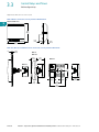
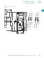
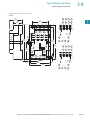
Machine Tool Relays
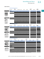
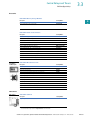
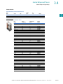
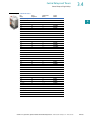
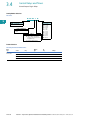
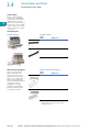
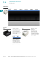
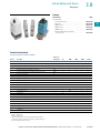
AC/DC Interface Module—
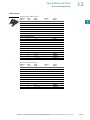
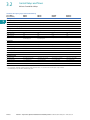
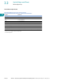
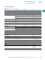
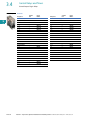
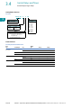
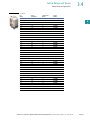
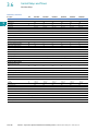
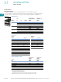
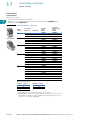
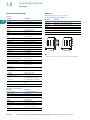
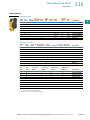
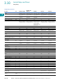
Controller Coil Voltage Ranges
C320DC
Controller Catalog
Number Prefix
Controller
Size or Rating
Coil Range
Volts AC
AE16, AE17, AE56,
AE57, CE15, CE55
A–F
24–240
G–K
48–240
AN16, AN56,
CN15, CN55
CN35
L–N
110–240
00–0
24–240
1–2
48–240
3
110–240
10–30A
24–240
60A
48–240
100A
110–240
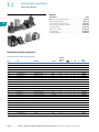
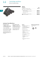
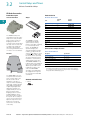
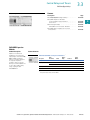
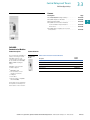
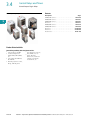
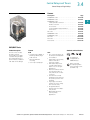
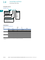
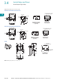
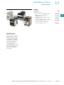
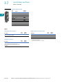
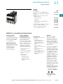
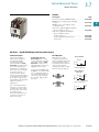
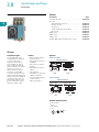
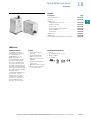
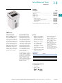
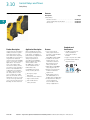
The Catalog Number C320DC
Interface Module is an
optically isolated solid-state
switch that provides a means
of operating AC coils with a
24 Vdc control signal. It acts
as a space-saving interposing
relay that can switch a
specified 50/60 Hz AC source
to the contactor or starter coil.
3.7
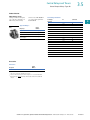
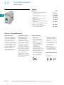
provisions for DIN rail
mounting.
3
The module will operate coils
within the voltage ranges
shown in the table to the left.
3
Design Characteristics
●
●
The module may be directly
attached to the coil terminals
of any Freedom Series
contactor or starter—NEMA
Sizes 00–3, D15, IEC Sizes
A–N and lighting contactors
10–100A. It also has
●
DC input: 24V ±10% at
mA nominal
AC operating voltage:
24–240 Vac ±10%
50/60 Hz
AC current rating:
10A make (inrush),
1A break (sealed)
3
3
3
3
3
3
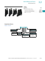
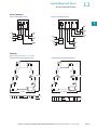
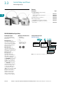
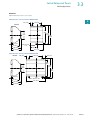
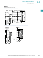
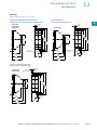
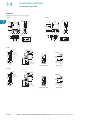
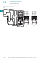
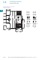
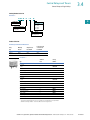
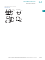
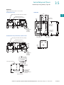
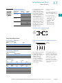
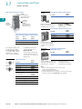
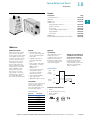
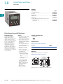
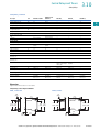
Typical Application—Solid-State Switch
Contactor Coil
24 Vdc
Input
Observe
Polarity on
Module
3
3
3
24–240 Vac
50/60 Hz
3
3
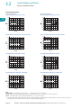
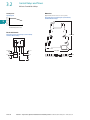
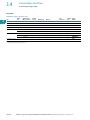
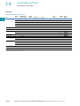
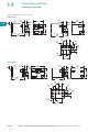
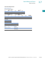
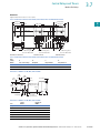
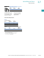
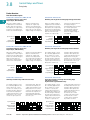
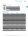
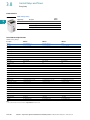
Technical Data and Specifications
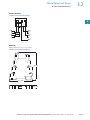
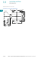
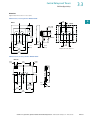
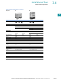
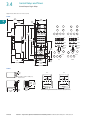
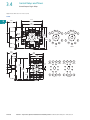
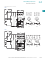
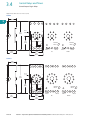
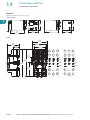
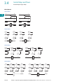
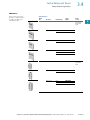
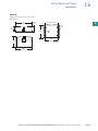
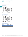
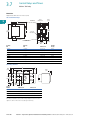
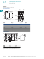
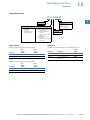
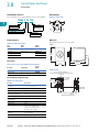
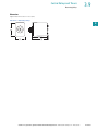
Example of Terminal Marking with 2NO and 2NC Contacts
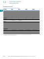
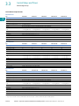
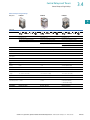
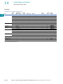
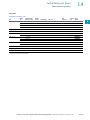
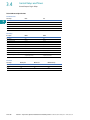
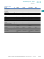
Contact Ratings—NEMA A600
Continuous Thermal Rating: 10A
Location
AC Volts
Make
Break
120
60
6.0
240
30
3.0
480
15
1.5
600
12
1.2
13
125
1.1
250
0.55
31
3
43
3
14
Continuous Thermal Rating: 5A
Make/Break Amperes
21
3
3
Contact Ratings—NEMA P300
DC Volts
Status
(NO or NC)
3
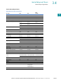
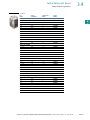
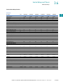
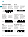
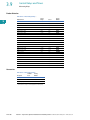
Magnet Coil Data
AC
Voltage
Pickup
Sealed
VA
Watts
VA
Watts
12–600V
80
49
7.5
2.4
DC
Voltage
Pickup
Amps
Watts
VA
Watts
12
6.4
76.8
0.28
3.36
24
3.2
76.8
0.14
3.36
48
1.6
76.8
0.07
3.36
120
0.64
76.8
0.028
3.36
22
32
3
44
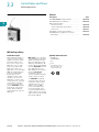
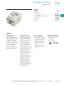
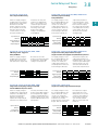
Relay terminals are identified
by a two-digit number in
accordance with International
Standards approved by
CENELEC (European
Committee for Electrotechnical Standardization).
The number is marked on
the relay and is used to
identify location and status
of the contacts.
The first digit indicates the
location of the contact on the
relay. The numbering begins
with 1 and continues without
a break from left to right.
The second digit indicates
the status of the contacts
(NO or NC). Terminal marking
1 and 2 mean NC and 3 and
4 mean NO.
3
3
3
3
3
3
Sealed
3
3
3
3
3
Volume 7—Logic Control, Operator Interface and Connectivity Solutions CA08100008E—January 2012 www.eaton.com
V7-T3-143