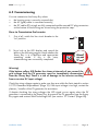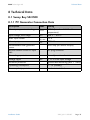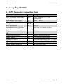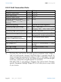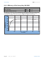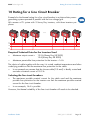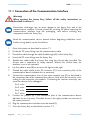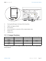
1
Sunny Boy SB 2500 and SB 3000
String Inverter for Photovoltaic Plants
Installation Guide
Version 1.0
SB25_30-11:SE0307
IMEN-SB25_30
SMA Technologie AG
Table of Contents
Table of Contents
1
Explanation of the Symbols Used . . . . . . . . . . . . 5
2
2.1
2.2
2.3
Foreword . . . . . . . . . . .
Target Group . . . . . . . . .
Appropriate Usage. . . . .
Validity of Documentation
3
Safety Instructions . . . . . . . . . . . . . . . . . . . . . . . . 9
4
4.1
4.2
Overview . . . . . . . . . . . . . . . . . . . . . . . . . . . . . . 11
Unit Description . . . . . . . . . . . . . . . . . . . . . . . . . . 11
External Dimensions . . . . . . . . . . . . . . . . . . . . . . . 12
5
5.1
5.2
5.3
Installation Requirements. . . . .
Installation Location Requirements
PV Generator Requirements . . . . .
Low Voltage Grid (AC) . . . . . . . .
6
6.1
6.2
Installation . . . . . . . . . . . . . . . . . . . . . . . . . . . . . 21
Mounting the Device. . . . . . . . . . . . . . . . . . . . . . . 21
Electrical Installation . . . . . . . . . . . . . . . . . . . . . . . 22
6.2.1
6.2.2
Connecting the AC Output . . . . . . . . . . . . . . . . . . . . . . . . . . .24
PV String (DC) Connection . . . . . . . . . . . . . . . . . . . . . . . . . . .30
6.3
Commissioning . . . . . . . . . . . . . . . . . . . . . . . . . . . 31
7
7.1
7.2
Opening and Closing the Sunny Boy . . . . . . . . 33
Opening the Sunny Boy . . . . . . . . . . . . . . . . . . . . 33
Closing the Sunny Boy . . . . . . . . . . . . . . . . . . . . . 33
8
8.1
Technical Data . . . . . . . . . . . . . . . . . . . . . . . . . . 35
Sunny Boy SB 2500 . . . . . . . . . . . . . . . . . . . . . . . 35
8.1.1
8.1.2
PV Generator Connection Data . . . . . . . . . . . . . . . . . . . . . . . .35
Grid Connection Data . . . . . . . . . . . . . . . . . . . . . . . . . . . . . .36
Installation Guide
.
.
.
.
.
.
.
.
..
..
..
..
.
.
.
.
.
.
.
.
.
.
.
.
.
.
.
.
.
.
.
.
.
.
.
.
.
.
.
.
.
.
.
.
.
.
.
.
.
.
.
.
.
.
.
.
.
.
.
.
.
.
.
.
.
.
.
.
.
.
.
.
.
.
.
.
.
.
.
.
.
.
.
.
.
.
.
.
.
.
.
.
.
.
.
.
.
.
.
.
SB25_30-11:SE0307
.
.
.
.
.
.
.
.
.
.
.
.
.
.
.
.
.
.
.
.
.
.
.
.
.
.
.
.
7
7
8
8
13
13
15
15
Page 3
SMA Technologie AG
Table of Contents
8.2
Sunny Boy SB 3000 . . . . . . . . . . . . . . . . . . . . . . . 37
8.2.1
8.2.2
PV Generator Connection Data . . . . . . . . . . . . . . . . . . . . . . . .37
Grid Connection Data . . . . . . . . . . . . . . . . . . . . . . . . . . . . . .38
8.3
General Data. . . . . . . . . . . . . . . . . . . . . . . . . . . . 39
8.3.1
8.3.2
Efficiency of the Sunny Boy SB 2500 . . . . . . . . . . . . . . . . . . . .40
Efficiency of the Sunny Boy SB 3000 . . . . . . . . . . . . . . . . . . . .41
8.4
Operating Parameters. . . . . . . . . . . . . . . . . . . . . . 42
8.4.1
8.4.2
8.4.3
8.4.4
Explanation of the Operating Parameters .
Parameter Settings for Germany . . . . . . .
Country-specific Parameter Settings . . . . .
Fixed Parameters . . . . . . . . . . . . . . . . . .
8.5
Certificate . . . . . . . . . . . . . . . . . . . . . . . . . . . . . . 49
8.5.1
8.5.2
CE Declaration of Conformity . . . . . . . . . . . . . . . . . . . . . . . . .49
SMA Grid Guard Certificate . . . . . . . . . . . . . . . . . . . . . . . . . .50
9
Replacing the Varistors . . . . . . . . . . . . . . . . . . . 51
10
Rating for a Line Circuit Breaker . . . . . . . . . . . . 55
11
11.1
The Communication Interface. . . . . . . . . . . . . . . 59
Connection of the Communication Interface. . . . . . . 60
11.1.1
Jumper Functions . . . . . . . . . . . . . . . . . . . . . . . . . . . . . . . . . .61
12
Contact. . . . . . . . . . . . . . . . . . . . . . . . . . . . . . . . 63
Page 4
SB25_30-11:SE0307
.
.
.
.
.
.
.
.
.
.
.
.
.
.
.
.
.
.
.
.
.
.
.
.
.
.
.
.
.
.
.
.
.
.
.
.
.
.
.
.
.
.
.
.
.
.
.
.
.
.
.
.
.
.
.
.
.
.
.
.
.42
.45
.47
.48
Installation Guide
SMA Technologie AG
Explanation of the Symbols Used
1 Explanation of the Symbols Used
To ensure optimum use of this document, note the following explanation of the symbols
used.
This symbol indicates an example.
This symbol indicates a note which, if ignored, will make the procedure or
operation more difficult.
This symbol indicates a fact which, if not observed, could result in damage
to components or represent a danger to persons. Read these passages
especially carefully.
Installation Guide
SB25_30-11:SE0307
Page 5
Explanation of the Symbols Used
Page 6
SB25_30-11:SE0307
SMA Technologie AG
Installation Guide
SMA Technologie AG
Foreword
2 Foreword
The Sunny Boy is equipped with the SMA grid guard. This is a type of automatic
disconnection device. This means that the Sunny Boy complies with the VDEW
(Verband der Elektrizitätswirtschaft – German Electricity Industry Association)
regulations for the connection and parallel operation of power-generating systems
to the low-voltage grid of the energy supply company and with DIN VDE 0126-11, which forms part of these regulations.
Refer to the operating manual for detailed information on troubleshooting and
operating the Sunny Boy as well as on the various communication options.
Sunny Design will assist you in the system design and checking of the string size for a
given type of inverter. Further information on Sunny Design is available at
www.SMA.de.
If you require further information, please call the Sunny Boy Hotline:
+49 (561) 95 22 - 499
2.1 Target Group
Warning!
The Sunny Boy may only be installed by trained specialists. The installer
must be approved by the local energy supplier. Read this installation
guide carefully. Ensure compliance with all prescribed safety regulations,
the technical connection requirements of the local energy supplier and
any other applicable provisions.
This installation guide is exclusively intended for qualified electricians and is intended
to assist with the speedy and correct installation and commissioning of the SMA Sunny
Boy SB 2500 and Sunny Boy SB 3000 inverters.
Installation Guide
SB25_30-11:SE0307
Page 7
SMA Technologie AG
Foreword
2.2 Appropriate Usage
Warning!
The Sunny Boy is designed for operation in grid-connected PV systems.
Use of the Sunny Boy for any purpose other than those specified in this
documentation will lead to the loss of the right to all warranty claims and
may lead to a fault in the device. This includes, among other things, the
operation with voltage sources without any current limit. When in doubt,
contact SMA.
2.3 Validity of Documentation
The Sunny Boy SB 2500 and Sunny Boy SB 3000 are identical in construction and only
differ in their technical data. This documentation uses the terms Sunny Boy or inverter
when referring to either device type. The device will be specified with its full name if the
information only refers to that particular device.
Page 8
SB25_30-11:SE0307
Installation Guide
SMA Technologie AG
Safety Instructions
3 Safety Instructions
Warning! Overvoltage!
Check the system design using the Sunny
Design tool (www.SMA.de) or by calling
the Sunny Boy Hotline. Overvoltages lead
to the destruction of the Sunny Boy.
Warning! High voltage!
Work on the Sunny Boy with the cover removed must be carried out by a
qualified electrician! High voltages are present in the device. Work is to
be carried out on the Sunny Boy only once the AC and DC voltages have
been disconnected from the Sunny Boy, and once it has been ensured that
the capacitors have been discharged.
The Sunny Boy must be disconnected from the grid and precautions must
be taken to prevent the grid being accidentally reconnected. In addition,
the connections to the PV generator must be disconnected.
After isolating the AC and DC voltage, you must wait approximately 30
minutes for the capacitors in the Sunny Boy to discharge. Only then is it
safe to open the unit by removing the cover to make sure that no voltage
is present in the device.
Warning! Electrostatic charge!
When working on the Sunny Boy and handling its assemblies, remember
to observe all ESD safety regulations. Electronic components are
susceptible to electrostatic charge. Discharge any electrostatic charge by
touching the grounded housing before handling any electronic
component.
Installation Guide
SB25_30-11:SE0307
Page 9
Safety Instructions
Page 10
SB25_30-11:SE0307
SMA Technologie AG
Installation Guide
SMA Technologie AG
Overview
4 Overview
4.1 Unit Description
The following diagram gives a schematic overview of the various components and
connection points inside the Sunny Boy with the cover removed:
Varistors, section 9
Communication socket
Communication socket (RS232, RS485, NLM
Piggy-Back, radio), section 11
Sunny Display
Operating status
LEDs
Jumper slot for
communication
Plug socket (AC),
section 6.2.1
PE (protective earth) connector for cover
Flat plug connection for grounding the cable shield for
RS232 and RS485 communication
Housing feed-through for the optional Electronic Solar Switch
PV input plugs (DC), section 6.2.2
Installation Guide
SB25_30-11:SE0307
Page 11
SMA Technologie AG
Overview
4.2 External Dimensions
225 mm
470 mm
490 mm
Page 12
SB25_30-11:SE0307
Installation Guide
SMA Technologie AG
Installation Requirements
5 Installation Requirements
Check that all of the requirements listed below are met before installing and
commissioning the Sunny Boy.
5.1 Installation Location Requirements
The Sunny Boy SB 2500 weighs 30 kg, the Sunny Boy SB 3000
weighs 32 kg. Take this weight into account when choosing the
installation location and method of installation.
The ambient temperature must not be outside the -25 °C to
+60 °C range.
30 / 32 kg
The Sunny Boy is designed for outdoor installation and should be
installed in a place where it is not exposed to direct sunlight. An
increased ambient temperature can reduce the yield of the PV
system. Installing the unit in badly ventilated, warm indoor locations
may also reduce yield.
The Sunny Boy is designed to be mounted on a vertical wall. However, if absolutely
necessary, the Sunny Boy can be installed tilted back at a maximum angle of 45°.
Vertical installation at eye-level is preferable for an optimum energy yield and maximum
operational comfort. If installing the unit outdoors, make sure that it is not slanting
forwards.
We advise against installing the unit in a horizontal position outdoors.
Install the inverter vertically or
tilting backward.
Installation Guide
Never install the inverter horizontally
or so that it tilts forward.
SB25_30-11:SE0307
Page 13
SMA Technologie AG
Installation Requirements
When choosing the installation location, be sure to observe the
following:
Warning, high voltage!
Unintentionally pulling out the DC plug connectors under load can
damage the plugs and could result in personal injury! Install the Sunny
Boy in such a way that it is not possible (e.g. for children) to unplug the
DC plug connector unintentionally.
Warning, risk of burning!
The temperature of the individual components in the housing, especially
the heatsinks, can exceed 60 °C. There is the danger of burn injury when
these parts are touched!
Warning!
Do not install the Sunny Boy on flammable construction materials, in areas
where highly inflammable materials are stored or in potentially explosive
environments!
When choosing the installation location, ensure there is enough space for heat to
dissipate! Under normal conditions, the following recommended values for the space
to be kept clear around the Sunny Boy should be followed:
Minimum clearance
Sides
20 cm
Top
20 cm
Underneath
20 cm
Front
5 cm
In a living area, the unit should not be mounted on
plasterboard walls or alike as otherwise audible
vibrations are likely to result.
We recommend securing the unit to a solid surface.
The Sunny Boy can make noises during operation
which could be perceived as a nuisance if installed
in a living area.
Page 14
SB25_30-11:SE0307
Installation Guide
SMA Technologie AG
Installation Requirements
5.2 PV Generator Requirements
The Sunny Boy is designed to be connected to up to three strings (PV modules wired in
series) having a homogenous structure (modules of the same type, identical orientation
and tilt).
Sunny Design will assist you in the system design and checking of the string size for a
given type of inverter. Further information on Sunny Design is available at
www.SMA.de.
The unit has six DC plug connectors (two for each string) for connecting the PV
generators. The connecting cables from the PV generators must also be fitted with this
type of plug connector. A pre-assembled set for connecting the free cable ends from a
string is available as an optional accessory. The SMA order codes for the various
connectors are as follows:
•
Multi-Contact 3 mm:
SWR-MC
•
Multi-Contact 4 mm:
MC-SET
•
Tyco:
TYCO-SET
Limit values for DC input
Max. voltage
600 V (DC)
Max. input current
12 A (DC)
5.3 Low Voltage Grid (AC)
The Sunny Boy must have a three-conductor connection to the grid (live (L), neutral (N),
protective earth (PE)).
The grid connection terminals on the AC connection
Cable
Wire
socket included in the accessories kit can take wires
diameter
cross-section
with a cross-section of up to 2.5 mm². The
accessories kit also contains a PG13.5 AC
connection socket for connecting cables with a crosssection between 9 mm² and 13.5 mm², while the
PG16 connection socket is used for cables with a
cross-section up to a maximum of 17 mm². For detailed instructions, see sections
"Connecting the AC Output with PG13.5" (Page 26) and "Connecting the AC Output
with PG16" (Page 28).
Warning!
We recommend using a 16 A line circuit
breaker to protect the power circuit. No
loads should be connected to this power
circuit.
Installation Guide
SB25_30-11:SE0307
Page 15
SMA Technologie AG
Installation Requirements
Rating for a Line Circuit Breaker in a Photovoltaic Power Generating
System Operated in Parallel to the Low Voltage Grid
Various factors should be taken into account when selecting line circuit breakers. These
include, for example:
•
The type of cable used (conductor material and insulation)
•
Ambient temperatures affecting the cables (higher temperatures result in a reduced
maximum current load)
•
Method of routing the cable (reduces the maximum current load)
•
Bundling cables together (reduces the maximum current load)
•
Loop impedance [Z] (in the event of a body contact this limits the current that can
flow and therefore determines the response behavior of the circuit breaker)
•
Sufficient distance between the circuit breakers so as to avoid undue heating (heat
can trigger the circuit breaker early)
•
Selectivity
•
Protection class of the connected load (VDE 0100, part 410), Protection against
electric shock
Please pay attention to section 10 "Rating for a Line Circuit Breaker" (Page 55).
The following standards should be followed in all cases:
•
DIN VDE 0298-4
(Cable routing and current-carrying capacity)
•
DIN VDE 0100, part 430
(Protective measures; protection of cable and
cords against overcurrent)
•
DIN VDE 0100, part 410
(Protective measures; protection against electric
shock)
Page 16
SB25_30-11:SE0307
Installation Guide
SMA Technologie AG
Installation Requirements
For optimum operation of the inverters, the grid impedance of the AC cable must not
exceed 1 Ohm. This is necessary, amongst other things, for the correct operation of the
impedance monitoring. In addition, we recommend dimensioning the cable crosssection so that output losses do not exceed 1 % at nominal power. Output losses as a
function of cable length and cross-section are shown in the graphs below. Multi-wire
cables with copper forward and return conductors are used.
Output Losses of the Sunny Boy SB 2500
Output losses
Do not use cables where losses will exceed 1.0 %
Cable length
The maximum cable lengths for the different cable cross-sections are as follows:
Cable cross-section
1.5 mm²
2.5 mm²
Max. length
9m
15.5 m
Installation Guide
SB25_30-11:SE0307
Page 17
SMA Technologie AG
Installation Requirements
Output Losses of the Sunny Boy SB 3000
Output losses
Do not use cables where losses will exceed 1.0 %
Cable length
Cable cross-section
1.5 mm²
2.5 mm²
Max. length
7.5 m
12.5 m
Page 18
SB25_30-11:SE0307
Installation Guide
SMA Technologie AG
Installation Requirements
The Sunny Boy is designed for operation on 220 - 240 V grids at a grid frequency of
50 / 60 Hz. When connecting an inverter to the public grid, follow the connection
requirements of the local grid operator.
Limit values for AC output
Voltage range (complying with DIN VDE 198 V ... 253 / 260 V a
0126-1-1)
Frequency range (complying with DIN 47.55 Hz ... 50.2 Hz
VDE 0126-1-1)
Voltage
range)
range
(extended
operating 180 V ... 265 V
Frequency range (extended operating 45.5 Hz ... 54.5 Hz
range)
55.5 Hz ... 64.5 Hz
a
The Sunny Boy can feed into the public grid at a maximum output voltage of
260 V for brief periods. However, DIN VDE 0126-1-1 stipulates that the 10minute average must not exceed a voltage of 253 V. That means, if the grid
voltage is constantly 254 V (e.g.), the inverter disconnects itself from the grid.
In this case, contact the local grid operator for assistance.
DIN VDE 0126-1-1 only applies in Germany. See section 8.4.3 "Countryspecific Parameter Settings" (Page 47) for all other preset country values of
your inverter.
Installation Guide
SB25_30-11:SE0307
Page 19
Installation Requirements
Page 20
SB25_30-11:SE0307
SMA Technologie AG
Installation Guide
SMA Technologie AG
Installation
6 Installation
6.1 Mounting the Device
To make the job easier, we recommend you use the
supplied wall bracket to mount the Sunny Boy. For
vertical installation and installation on solid concrete
or block walls, for example, you can fit the bracket
using 6 mm x 50 mm hexagon bolts to DIN 571
standard, stainless steel type, and with wall anchors
type SX 8.
When selecting the mounting materials, be sure to
take into account the weight of the Sunny Boy (SB
2500 (30 kg), SB 3000 (32 kg)).
If you do not want to use the supplied wall bracket as a template, observe the
dimensions shown in the illustration below. The procedure for mounting the inverter
using the wall bracket is described on the following pages.
108.75 mm
117 mm
217.5 mm
Installation Guide
179.5 mm
182 mm
112 mm
SB25_30-11:SE0307
Page 21
SMA Technologie AG
Installation
1.
Mount the wall bracket (1). To mark the
positions to drill the holes, you can use the wall
bracket as a drilling template.
2.
Now hang the Sunny Boy onto the wall bracket
(2) using its upper mounting plate so that it
cannot be moved sideways.
3.
Secure the Sunny Boy in position by screwing
the supplied M6x10 bolt into the central
threaded hole at the bottom of the bracket (3).
4.
Make sure that the Sunny Boy is positioned
securely on the bracket.
6.2 Electrical Installation
Warning!
Make sure to check the polarity of the strings before connecting them.
The wiring for the Sunny Boy is shown schematically in the following figure:
AC connection, max. 2.5 mm²
String 1
String 2
String 3
Page 22
SB25_30-11:SE0307
Installation Guide
SMA Technologie AG
Installation
View from below
Opening for the optional
Electronic Solar Switch
Plug and socket
connector for
connection of the
solar modules
Installation Guide
AC plug for the grid
connection
Opening for optional
communication via
RS232, RS485 or
radio (PG16)
SB25_30-11:SE0307
Page 23
SMA Technologie AG
Installation
6.2.1 Connecting the AC Output
Warning! Voltage!
Before you connect the mains cable to the AC connection socket, make
sure that no voltage is present at the cable.
A round plug connector system is used, which allows various cable diameters to be
used in the cable outlet. For this reason, the accessories kit includes a PG13.5 pressure
screw and a PG16 pressure screw. Check which screw fitting is the right one for your
AC cable.
To connect up the AC output, follow these steps:
1.
Check the grid voltage. If this is higher than 253 V, the Sunny Boy will not be fully
operational. In this case, contact the local grid operator for assistance.
2.
Isolate the grid connection (switch the line circuit
breaker to its "off" position), make sure it cannot
be switched back on, and test to make sure no
voltage is present.
3.
Peel off approximately 30 mm of the cable
jacket. Shorten L and N by 5 mm.
4.
Strip approximately 4 mm of the cable's
insulation.
Page 24
SB25_30-11:SE0307
Off!
approx. 25
approx.
4 mm
Installation Guide
SMA Technologie AG
5.
Installation
Now take the AC connection socket parts from the accessories kit and connect up
the cable, with shielding and insulation stripped, as described on the following
pages.
Cord grip
for PG13.5
Sealing ring
for PG13.5
Pressure screw
for PG13.5
Threaded sleeve
Socket element
PG16 pressure screw for
large cable cross-sections
Installation Guide
SB25_30-11:SE0307
Page 25
SMA Technologie AG
Installation
Connecting the AC Output with PG13.5
To connect a cable with a maximum cross-section of 13.5 mm², proceed as follows.
1.
2.
Press the sealing ring (1) into the cord grip (2).
(1)
(2)
Now slide the pressure screw (3) over the cable
first of all, followed by the cord grip with the sealing ring (4) in it. Now slide the
threaded sleeve (5) over the cable.
(3)
(4)
(5)
3.
4.
Now connect the individual conductors to the socket element in sequence.
-
Protective earth PE (green/yellow) to the
screw terminal with the earth sign.
-
Neutral conductor N (blue) to screw terminal
1.
-
Live L (brown or black) to screw terminal 2.
-
Terminal 3 remains unused.
Make sure
connected.
the
wires
(6)
are
N
PE
L
securely
(6)
Page 26
SB25_30-11:SE0307
Installation Guide
SMA Technologie AG
5.
Now screw the threaded sleeve (7) onto the socket element (8) and tighten it.
(8)
6.
Installation
(7)
Now screw the pressure screw (9)
into the threaded sleeve (10) and
tighten it. The cord grip with the
sealing ring is pressed into the
threaded sleeve and can no longer
be seen.
(10)
(9)
The AC connection socket is now fully assembled.
If you are not going to connect up the Sunny Boy immediately, close the socket element
using the cap supplied in the accessories kit.
If the Sunny Boy is already installed, you can now connect up the fully assembled AC
connection socket to the flange plug on the Sunny Boy. To do this, remove the protective
cap from the flange plug on the Sunny Boy. Firmly tighten the threaded ring on the AC
connection socket to the flange plug to seal the connection and secure it.
Warning!
Do not switch the line circuit breaker on yet! The Sunny Boy may only be
connected to the AC grid once the PV strings are connected and the device
is securely closed.
Installation Guide
SB25_30-11:SE0307
Page 27
SMA Technologie AG
Installation
Connecting the AC Output with PG16
To connect a cable with a cross-section between 13.5 mm² and 16 mm², proceed as
follows.
1.
First of all, slide the pressure screw with the PG16 screw fitting (1) onto the cable.
Now slide the threaded sleeve (2) over the cable.
(1)
(2)
2.
3.
Now connect the individual conductors to the socket element in sequence.
-
Protective earth PE (green/yellow) to the
screw terminal with the earth sign.
-
Neutral conductor N (blue) to screw terminal
1.
-
Live L (brown or black) to screw terminal 2.
-
Terminal 3 remains unused.
Make sure
connected.
the
wires
(3)
are
N
PE
L
securely
(3)
4.
Now screw the threaded sleeve (4) onto the socket element (5) and tighten it.
(5)
Page 28
(4)
SB25_30-11:SE0307
Installation Guide
SMA Technologie AG
5.
Now screw the pressure screw (6)
into the threaded sleeve (7) and
tighten it.
6.
Firmly tighten the screw fitting against
the seal and strain relief.
Installation
(7)
(6)
The AC connection socket is now fully assembled.
If you are not going to connect up the Sunny Boy immediately, close the socket element
using the cap supplied in the accessories kit.
If the Sunny Boy is already installed, you can now connect up the fully assembled AC
connection socket to the flange plug on the Sunny Boy. To do this, remove the protective
cap from the flange plug on the Sunny Boy. Firmly tighten the threaded ring on the AC
connection socket to the flange plug to seal the connection and secure it.
Warning!
Do not switch the line circuit breaker on yet! The Sunny Boy may only be
connected to the AC grid once the PV strings are connected and the device
is securely closed.
Installation Guide
SB25_30-11:SE0307
Page 29
SMA Technologie AG
Installation
6.2.2 PV String (DC) Connection
To connect up the input, follow these steps:
1.
Make sure the PV generator connectors have
the right polarity and do not exceed the
maximum string voltage of 600 V (DC). See
also section 5.2 "PV Generator Requirements"
(Page 15).
Warning!
Dangerously high voltages may be present. Danger of death!
2.
Taking one DC plug connector at a time,
measure the direct current voltage between one
DC plug connector of a string and ground
potential.
3.
If the measured voltages are constant and their
total is roughly the same as the open circuit
voltage of the string, then there is a ground fault
in this string. Its approximate location can be
deduced from the relationships between the
voltages.
Warning!
Do not connect strings to the Sunny Boy that contain a ground fault until
you have fixed the ground fault in the PV generator!
4.
Repeat points 2 and 3 for each string.
5.
Connect up the faultless PV generator strings to
the inverter.
6.
Close the unused DC input sockets with the caps
included in the delivery.
Page 30
SB25_30-11:SE0307
Installation Guide
SMA Technologie AG
Installation
6.3 Commissioning
You can commission the Sunny Boy when:
•
the housing cover is securely screwed shut,
•
the AC (grid) cable is connected correctly,
•
the DC cables (PV strings) are fully connected and the unused DC plug connectors
on the bottom of the housing are closed using the protective caps.
How to Commission the Inverter
1.
First of all, switch the line circuit breaker to the
"on" position.
2.
Now look at the LED display and consult the
table on the following page to check whether the
Sunny Boy is in a fault-free and appropriate
operating mode. If this is the case,
commissioning was successfully completed.
On
Warning!
If the bottom yellow LED flashes four times at intervals of one second, the
grid voltage and the PV generator must be immediately disconnected
from the Sunny Boy! There is a risk of damage to the inverter resulting
from excessive DC input voltage!
Check the string voltages again to make sure they are within the limits stated in section
5.2 "PV Generator Requirements" (Page 15). If the input voltage is too high, contact the
planner / installer of the PV generator for assistance.
If despite checking the string voltages the LED signal occurs again when the PV
generator is connected to the Sunny Boy, disconnect the PV generator from the Sunny
Boy again and contact SMA Technologie AG (see section 12 "Contact" (Page 63)).
Installation Guide
SB25_30-11:SE0307
Page 31
SMA Technologie AG
Installation
Green
Red
Yellow
Status
shines continuously
is not shining
is not shining
OK (working mode)
shines continuously
is not shining
failure
shines continuously
OK (initialization)
is not shining
is not shining
OK (stop)
shines continuously
is not shining
failure
is not shining
is not shining
OK (waiting, grid
monitoring)
shines continuously
is not shining
failure
is not shining
is not shining
OK (derating)
shines continuously
is not shining
failure
is not shining
is not shining
OK (night
shutdown)
shining/flashing
failure
is not shining
failure
shining/flashing
failure
flashes quickly
(3 x per second)
flashes slowly
(1 x per second)
briefly goes out
(approx. 1 x per
second)
is not shining
shines continuously
For a detailed description of the fault messages and their causes, see the operating
manual.
Page 32
SB25_30-11:SE0307
Installation Guide
SMA Technologie AG
Opening and Closing the Sunny Boy
7 Opening and Closing the Sunny Boy
Warning!
If you need to open the device for whatever reason, pay attention to
section 3 "Safety Instructions" (Page 9).
7.1 Opening the Sunny Boy
Warning!
Follow the sequence below under all circumstances!
1.
Switch the line circuit breaker to the "off" position.
2.
Disconnect the PV generator from the Sunny Boy.
3.
Wait 30 minutes!
4.
Remove the four screws from the housing cover and pull the cover forward
smoothly. Remove the PE connection from the cover. Loosen the locking on the PE
connectors on the cover when you remove them.
7.2 Closing the Sunny Boy
Warning!
Follow the sequence below under all circumstances!
1.
Reconnect the protective earth (PE) to the housing cover. Now secure the housing
cover of the Sunny Boy by evenly tightening the four screws.
2.
Connect the PV generator.
3.
Switch the line circuit breaker to the "on" position.
4.
Now check whether the LED display on the Sunny Boy indicates that the device is
functioning correctly.
Installation Guide
SB25_30-11:SE0307
Page 33
Opening and Closing the Sunny Boy
Page 34
SB25_30-11:SE0307
SMA Technologie AG
Installation Guide
SMA Technologie AG
Technical Data
8 Technical Data
8.1 Sunny Boy SB 2500
8.1.1 PV Generator Connection Data
Description
Abbr.
Setting
Max. input open circuit voltage
UPV 0
600 V (based on -10 °C cell
temperature)
Input voltage, MPP range
UPV
224 V ... 600 V
Max. input current
IPV, max
12 A
Max. input power
PDC
2700 W
Recommended total generator
power
3000 Wp (for central Europe)
All-pole isolator on the DC input
side
DC plug connector
Overvoltage protection
thermally monitored varistors
Voltage ripple
UPP
< 10 % of the input voltage
Insulation protection
ground fault monitoring (Riso > 1 MΩ)
Operating consumption
< 7 W (standby)
Reverse polarity protection
via short-circuit diode
Installation Guide
SB25_30-11:SE0307
Page 35
SMA Technologie AG
Technical Data
8.1.2 Grid Connection Data
Description
Abbr.
Setting
Nominal output power
PACnom
2300 W
Peak output power
PAC, max 2500 W
Nominal output current
IACnom
10 A
Harmonic distortion of output
KIAC
current (at KUgrid < 2 %, PAC > 0.5
PACnom)
<4%
Short-circuit proofing
grid-side via current regulation
Operating range, grid voltage
UAC
180 ... 265 V AC
Germany: 198 ... 253 / 260 V ACb)
Operating range, grid frequency
fAC
All-pole isolator on grid side
Power factor (based on the
current's fundamental frequency)
47.55 ... 50.2 Hz
automatic disconnection device (SMA
grid guard 2), double implementation
cos phi
1 (at nominal power output)
Overvoltage category
III
Test voltage (DC)
1.95 kV (1 s routine testing / 5 s type
testing)
Test surge voltage
4 kV (serial interface: 6 kV)
Operating consumption in night
mode
0.25 W
b)
The Sunny Boy can feed into the public grid at a maximum output voltage of
260 V for brief periods. However, DIN VDE 0126-1-1 stipulates that the 10minute average must not exceed a voltage of 253 V. That means, if the grid
voltage is constantly 254 V (e.g.), the inverter disconnects itself from the grid.
In this case, contact the local grid operator for assistance.
DIN VDE 0126-1-1 only applies in Germany. See section 8.4.3 "Countryspecific Parameter Settings" (Page 47) for all other preset country values
of your inverter.
Page 36
SB25_30-11:SE0307
Installation Guide
SMA Technologie AG
Technical Data
8.2 Sunny Boy SB 3000
8.2.1 PV Generator Connection Data
Description
Abbr.
Setting
Max. input open circuit voltage
UPV 0
600 V (based on -10 °C cell
temperature)
Input voltage, MPP range
UPV
268 V ... 600 V
Max. input current
IPV, max
12 A
Max. input power
PDC
3200 W
Recommended total generator
power
3600 Wp (for central Europe)
All-pole isolator on the DC input
side
DC plug connector
Overvoltage protection
thermally monitored varistors
Voltage ripple
UPP
< 10 % of the input voltage
Insulation protection
ground fault monitoring (Riso > 1 MΩ)
Operating consumption
< 7 W (standby)
Reverse polarity protection
via short-circuit diode
Installation Guide
SB25_30-11:SE0307
Page 37
SMA Technologie AG
Technical Data
8.2.2 Grid Connection Data
Description
Abbr.
Setting
Nominal output power
PACnom
2750 W
Peak output power
PAC, max 3000 W
Nominal output current
IACnom
12 A
Harmonic distortion of output
KIAC
current (at KUgrid < 2 %, PAC > 0.5
PACnom)
<4%
Short-circuit proofing
grid-side via current regulation
Operating range, grid voltage
UAC
180 ... 265 V AC
Germany: 198 ... 253 / 260 V ACb)
Operating range, grid frequency
fAC
All-pole isolator on grid side
Power factor (based on the
current's fundamental frequency)
47.55 ... 50.2 Hz
automatic disconnection device (SMA
grid guard 2), double implementation
cos phi
1 (at nominal power output)
Overvoltage category
III
Test voltage (DC)
1.95 kV (1 s routine testing / 5 s type
testing)
Test surge voltage
4 kV (serial interface: 6 kV)
Operating consumption in night
mode
0.25 W
b)
The Sunny Boy can feed into the public grid at a maximum output voltage of
260 V for brief periods. However, DIN VDE 0126-1-1 stipulates that the 10minute average must not exceed a voltage of 253 V. That means, if the grid
voltage is constantly 254 V (e.g.), the inverter disconnects itself from the grid.
In this case, contact the local grid operator for assistance.
DIN VDE 0126-1-1 only applies in Germany. See section 8.4.3 "Countryspecific Parameter Settings" (Page 47) for all other preset country values
of your inverter.
Page 38
SB25_30-11:SE0307
Installation Guide
SMA Technologie AG
Technical Data
8.3 General Data
For a detailed description of the device, see the operating manual.
General data
Protection degree (DIN EN 60529)
IP65
Dimensions (w x h x d)
434 mm x 295 mm x 214 mm
(approx.)
Weight
Sunny Boy SB 2500: approx. 30 kg
Sunny Boy SB 3000: approx. 32 kg
External interfaces
Data transmission over mains power line
optional
Data transmission over separate data cable
optional,
RS232
galvanically isolated
Wireless data transmission
optional
Installation Guide
/
SB25_30-11:SE0307
RS485,
Page 39
SMA Technologie AG
Technical Data
8.3.1 Efficiency of the Sunny Boy SB 2500
Efficiency
Max. efficiency
ηmax
94.1 %
European standard efficiency
ηeuro
93.2 %
Efficiency [%]
The efficiency of the Sunny Boy SB 2500 depends mainly on the input voltage of the
connected PV strings. The lower the input voltage, the higher the efficiency.
Pac [kW]
Page 40
SB25_30-11:SE0307
Installation Guide
SMA Technologie AG
Technical Data
8.3.2 Efficiency of the Sunny Boy SB 3000
Efficiency
Max. efficiency
ηmax
95 %
European standard efficiency
ηeuro
93,6 %
Efficiency [%]
The efficiency of the Sunny Boy SB 3000 depends mainly on the input voltage of the
connected PV strings. The lower the input voltage, the higher the efficiency.
Pac [kW]
Installation Guide
SB25_30-11:SE0307
Page 41
SMA Technologie AG
Technical Data
8.4 Operating Parameters
8.4.1 Explanation of the Operating Parameters
Name
Explanation
ACVtgRPro
Voltage rise protection (only relevant for Germany).
Sunny Boys can feed into the public grid in Germany with up to
260 V AC. However, DIN VDE 0126-1-1 stipulates that the
average AC voltage over 10 minutes must not exceed 253 V. If
the average over 10 minutes exceeds the threshold value of 253
V, the inverter disconnects itself from the grid. Once the average
over 10 minutes returns to a value of less than 253 V, the inverter
resumes grid feeding. If voltage rise protection is not required in
the relevant grid area (outside Germany), it can be deactivated
by presetting the LDVtgC parameter. In this event, only the fast
cut-off via the Uac-Max parameter intervenes.
AntiIsland-Ampl
Amplification of the AntiIsland process (alternative anti-islanding
process, which is deactivated for Germany).
AntiIsland-Freq
Repetition rate of the AntiIsland process (alternative antiislanding process, which is deactivated for Germany).
Betriebsart
Operating mode of the Sunny Boy:
MPP-Betrieb: Maximum Power Point
Konstantspg.: constant voltage mode (nominal voltage is
defined in "Usoll-Konst").
Stop: disconnection from grid, no operation.
Turbine: operating mode for wind turbine systems.
Default
Used for setting country-specific information.
GER/VDE0126-1-1: country-specific parameter settings for
Germany in accordance with DIN VDE 0126-1-1.
SP/RD1663: country-specific parameter settings for Spain.
GB/G83: country-specific parameter settings for Great Britain.
Other: here, parameter settings can be defined for countries for
which no predefined setting exists.
Trimmed: if country-specific parameters have been changed,
"trimmed" is shown on the display.
Off_Grid: settings for inverters which are operated in a standalone grid. More detailed information can be found in the Sunny
Island manual.
Page 42
SB25_30-11:SE0307
Installation Guide
SMA Technologie AG
Technical Data
Name
Explanation
dFac-Max
Maximum "grid frequency change" before the grid monitoring
system disconnects the device from the grid.
dZac
Maximum "grid impedance change" before the grid monitoring
system disconnects the device from the grid.
E_Total
Total energy yield for the inverter. This change may be
necessary when you replace the Sunny Boy and want to use the
data stored in the old device.
Fac-delta-
Maximum frequency, above (Fac-delta+) and below (Fac-delta-)
the grid frequency of 50 or 60 Hz, before the grid monitoring
system disconnects the device from the grid.
Fac-delta+
Fac-Pderating
Frequency-dependent output limitation.
Fac-Tavg
Averaging time of grid frequency measurement.
h_Total
Total hours of operation for the inverter. The changes may be
necessary when you exchange your Sunny Boy and want to use
the data from the old device.
I-NiTest
Setting the impulse for impedance monitoring. This parameter
only functions when the Sunny Boy is deactivated (disconnected
on the AC side) or in "Stopp" mode.
Speicherfunktion
Default parameter: returns all parameters to the factory settings.
Reset Betriebsdaten: returns all user level parameters to the
factory settings.
Reset Fehler: resets a permanent error.
Speicher/Storage
Permanent: modified parameters are stored in the EEPROM and
can be used even when the Sunny Boy has been restarted.
Volatil: prevents the parameters being stored in the EEPROM,
the parameters are only stored until the next restart.
T-Start
The period the Sunny Boy waits after all switch-on conditions
have been satisfied.
T-Stop
The period the Sunny Boy waits before disconnecting from the
grid.
Uac-Min
Lower (Uac-Min) and upper (Uac-Max) limits of the allowable
AC voltage (stand-alone grid recognition), before the grid
monitoring system disconnects the device from the grid.
Uac-Max
Uac-Tavg
Installation Guide
Averaging time for measuring grid frequency
SB25_30-11:SE0307
Page 43
SMA Technologie AG
Technical Data
Name
Explanation
Upv-Start
The DC voltage required before the inverter begins feeding
power into the grid.
This value is above the minimum MPP voltage which is required
in order to always guarantee safe connection to the grid, and to
minimize grid relay wear.
If, after disconnection from the grid, and in the absence of any
further faults, the inverter does not automatically reconnect to the
grid, this parameter can be decreased in small steps.
It must be noted that if the value is set too low, this leads to an
increased number of connections to the grid, and thus to
increased wear of components.
Usoll-Konst
Page 44
PV desired voltage for constant operational voltage. These
parameters are only important when the "Betriebsart" parameter
is set to U-konst.
SB25_30-11:SE0307
Installation Guide
SMA Technologie AG
Technical Data
8.4.2 Parameter Settings for Germany
Warning!
Unauthorized changes to the operating parameters may result in:
•
injury or accidents as a result of changing the internal safety routines
in the Sunny Boy,
•
voiding the Sunny Boy's operating approval certificate,
•
voiding the Sunny Boy's warranty.
Never change the parameters of your Sunny Boy without express
authorization and instructions.
The grayed-out parameters are only displayed in installer mode.
Name
Short
descr.
Value range
ACVtgRPro
V
AntiIslandAmpl*
grd
Factory setting
Sunny Boy
SB 2500
Sunny Boy
SB 3000
230 ... 300
253
253
0 ... 10
0
0
AntiIsland-Freq* mHz
0 ... 2000
500
500
Betriebsart
MPP,
Konstantspg.,
Stop, Turbine
MPP
MPP
Default *
GER/VDE0126- GER/VDE0126-1-1 GER/VDE0126-1-1
1-1, GB/G83,
Off_Grid,
SP/RD1663,
Other, trimmed
dFac-MAX *
Hz/s
0.005 ... 4.0
4
4
dZac*
mOhm
0 ... 20000
700
700
E_Total
kWh
0 ... 200000
Fac-delta+ *
Hz
0 ... 4.5
0.19
0.19
Fac-delta- *
Hz
0 ... 4.5
2.45
2.45
h_Total
h
0 ... 200000
I-NiTest *
mA
0 ... 15000
8000
9000
permanent,
volatil
permanent
permanent
Speicher/
Storage
Installation Guide
SB25_30-11:SE0307
Page 45
SMA Technologie AG
Technical Data
Name
Short
descr.
Speicherfunkt.
Value range
Factory setting
Sunny Boy
SB 2500
Sunny Boy
SB 3000
Default
Parameter,
Reset
Betriebsdaten,
Reset Fehler
no
no
T-Start *
s
5 ... 300
10
10
T-Stop
s
1 ... 1800
2
2
Uac-Max *
V
180 ... 300
260
260
Uac-Min *
V
180 ... 300
198
198
Upv-Start
V
250 ... 600/
290 ... 600
300
330
Usoll-Konst
V
250 ... 600
600
600
Parameters designated with * are safety-related grid monitoring parameters. To
change the SMA grid guard parameters, you must enter your personal SMA grid
guard password (Inst.-Code). Call the Sunny Boy Hotline to obtain your personal
SMA grid guard password.
Page 46
SB25_30-11:SE0307
Installation Guide
SMA Technologie AG
Technical Data
8.4.3 Country-specific Parameter Settings
The parameters listed below represent country-specific settings and are only displayed
in installer mode. All other parameters are international and can be viewed in the table
in section 8.4.2 "Parameter Settings for Germany" (Page 45).
Sunny Boy SB 2500
Name
Short
descr.
Country settings
Germany
Default
Great Britain
Spain
GER/VDE0126-1-1 GB/G83
SP/RD1663
dFac-Max
Hz/s
4
0.2
2
dZac-Max
mOhm
700
350
350
Fac-delta-
Hz
2.45
0.5
0.98
Fac-delta+
Hz
0.19
0.5
0.98
I-NiTest
mA
8000
0
0
T-Start
s
10
180
10
Uac-Min
V
198
209
199
Uac-Max
V
260
261
250
Great Britain
Spain
Sunny Boy SB 3000
Name
Short
descr.
Country settings
Germany
Default
GER/VDE0126-1-1 GB/G83
SP/RD1663
dFac-Max
Hz/s
0.25
0.2
2
dZac-Max
mOhm
700
350
350
Fac-delta-
Hz
2.45
0.5
0.98
Fac-delta+
Hz
0.19
0.5
0.98
I-NiTest
mA
9000
0
0
T-Start
s
10
180
10
Uac-Min
V
198
209
199
Uac-Max
V
260
261
250
Installation Guide
SB25_30-11:SE0307
Page 47
SMA Technologie AG
Technical Data
8.4.4 Fixed Parameters
The following parameters are displayed in the parameter list but cannot be changed:
Name
Short
descr.
Value range
Sunny Boy SB 2500
Sunny Boy SB 3000
Fac-Tavg
ms
160
160
Plimit
W
2500
3000
ms
80
80
Fac-Pderating
SMA-SN
Software-BFR
Software-SRR
Uac-Tavg
Page 48
SB25_30-11:SE0307
Installation Guide
SMA Technologie AG
Technical Data
8.5 Certificate
8.5.1 CE Declaration of Conformity
CE Declaration of Conformity
for utility interactive inverters
Product:
Type:
Sunny Boy
SB 700, SB 1100, SB 1100LV, SB 1700, SB 2100TL,
SB 2500, SB 2800i, SB 3000, SB 3300TL, SB 3300TL HC
We declare that the above specified devices are compliant with the regulations of the European
Community, in terms of the design and the version fabricated by SMA. This especially applies
for the EMC Regulation defined in 89/336/EWG and the LV- regulation defined in
73/23/EWG.
The devices are compliant with the following standards:
EMC:
Emission:
Utility Interference:
Immunity:
Safety:
Semiconductor-Converter:
DIN
DIN
DIN
DIN
DIN
DIN
DIN
DIN
DIN
EN 61000-6-3: 2002-08
EN 61000-6-4: 2002-08
EN 55022: 2003-09, Class B
EN 61000-3-3: 2002-05
EN 61000-3-2: 2001-12
EN 61000-6-1: 2002-08
EN 61000-6-2: 2002-08
EN 50178: 1998-04
EN 60146-1-1: 1994-03
The above mentioned devices are therefore marked with a CE sign.
Note:
This declaration of conformity becomes invalid in case
·
the product is modified, complemented or changed,
·
and/or components, other than those belonging to the SMA accessories, are installed in the product,
·
as well as in case of incorrect connection or inproper usage
without explicit written confirmation by SMA.
Niestetal, 13.03.2006
i.V. Frank Greizer
(Head of Development Department Solar Technology)
SB-K16A-CE-12:BE1706
SMA Technologie AG
SMA Technologie AG
Hannoversche Strasse 1-5
34266 Niestetal
Tel. +49 561 9522 – 0
Fax +49 561 9522 – 100
www.SMA.de
[email protected]
Installation Guide
SB25_30-11:SE0307
Page 49
Technical Data
SMA Technologie AG
8.5.2 SMA Grid Guard Certificate
The Sunny Boy is equipped with the automatic disconnection device “SMA grid guard”
which has been awarded a certificate of confidence by the Professional Association for
Electric Technology and Precision Mechanics..
Page 50
SB25_30-11:SE0307
Installation Guide
SMA Technologie AG
Replacing the Varistors
9 Replacing the Varistors
The Sunny Boy is a complex high-technology device. As a result, the possibilities for
fixing faults on site are limited to just a few items. Do not attempt to carry out repairs
other than those described here. Use the SMA Technologie AG 24-hour replacement
service and repair service instead.
If the red LED on the status display shines continuously during operation, you should first
of all make sure that there is no ground fault in the PV generator.
1.
Disconnect the Sunny Boy from the low
voltage grid (switch the line circuit breaker to
its "off" position or pull out the AC plug).
Make sure the grid cannot be inadvertently
reconnected.
Off
You must make sure that no voltage is present
at the AC output before opening the Sunny
Boy.
2.
Disconnect the DC plug connectors for all
strings.
3.
Disconnect the PV generators from the Sunny
Boy.
4.
Taking one DC plug connector at a time,
measure the voltages between one DC plug
connector of a string and ground potential.
Pay attention to the safety instructions!
5.
Measure the voltage between DC plug
connectors and ground potential.
Caution! Dangerously high voltages may be present. Danger of death!
Installation Guide
SB25_30-11:SE0307
Page 51
Replacing the Varistors
6.
SMA Technologie AG
If the measured voltages are constant and their total is roughly the same as the
open circuit voltage of the string, then there is a ground fault in this string. Its
approximate location can be deduced from the relationships between the
voltages.
Repeat points 3 and 4 for each string.
If you found a ground fault, it is probably not necessary to replace the varistors.
Instead, make sure the ground fault is fixed. Generally the PV generator's installer
should be hired for this job. In this case continue as described under point 10, but
without reconnecting the faulty string! Protect its DC plug against accidental touch
or contact (e.g. by fitting the protective caps or using sufficient high-voltage
insulating tape).
If you did not find any ground fault in the PV generators, it is likely that one of the
thermally monitored varistors has lost its protective function. These components
are wearing parts. Their functioning diminishes with age or following repeated
responses as a result of overvoltages. You can now check these varistors in the
following way, paying attention to the safety instructions in section 3 "Safety
Instructions" (Page 9):
7.
Remove the screws securing the cover and remove the cover from the Sunny Boy.
Disconnect the PE connection from the cover. Make sure that no voltage is
present.
8.
Use a continuity tester to check all the varistors and see if there is a conducting
connection between connectors 2 and 3. If there is no connection, then that
varistor is not working. The positions of the varistors in the Sunny Boy can be seen
in the figure in section 4.1 "Unit Description" (Page 11).
Page 52
SB25_30-11:SE0307
Installation Guide
SMA Technologie AG
9.
Replace the varistor in question with a new
one as shown in the illustration to the right.
Ensure the varistor is installed the right way
around! If you do not receive a special tool
for operating the terminal clamps together
with your replacement varistors, contact
SMA. As an alternative, the terminal contacts
can be operated using a suitable
screwdriver. Since the failure of one varistor
is generally due to factors that affect all
varistors in a similar way (temperature, age,
inductive overvoltages), it is highly
recommended that you replace both
varistors, not just the one that is obviously
defective. The varistors are specially
manufactured for use in the Sunny Boy and
are not commercially available. They must
be ordered directly from SMA Technologie
AG (SMA order code: SB-TV4).
Replacing the Varistors
Insert the special
tool to open the
terminal clamp
Remove the
varistor
The pole with the small
loop (crimp) must be
fitted to terminal 1 when
replacing the varistor.
Warning!
If no spare varistors are available on site, the Sunny Boy can once again
feed into the grid. The input is no longer protected against overvoltages!
Replacement varistors should be obtained as soon as possible. In systems
with a high risk of overvoltages, the Sunny Boy should not be operated
with defective varistors!
10. Reconnect the PE connection on the cover and close the Sunny Boy.
11. Connect up the faultless PV generator strings
to the inverter.
12. Close the unused DC input sockets with the
caps included in the delivery.
13. Switch the line circuit breaker to the "on"
position.
Installation Guide
On
SB25_30-11:SE0307
Page 53
Replacing the Varistors
SMA Technologie AG
14. Now check whether the LED display on the
Sunny Boy indicates that the device is
functioning correctly.
If no ground fault and no defective varistor were found, there is probably a fault in the
Sunny Boy. In this case, contact the SMA Hotline to discuss what to do next.
Page 54
SB25_30-11:SE0307
Installation Guide
SMA Technologie AG
Rating for a Line Circuit Breaker
10 Rating for a Line Circuit Breaker
Example for the thermal rating for a line circuit breaker in a photovoltaic powergenerating system operated in parallel with the low voltage grid.
We assume a PV system with 9 Sunny Boy inverters, with three inverters per
phase.
PhotovoltaikPhotovoltaic
Stringwechsel
string
inverter richter
Betrieb
Operation
Erdschluss
Earth
Fault
Störung
Failure
PhotovoltaikPhotovoltaic
Stringwechsel
string
inverter richter
Betrieb
Operation
Erdschluss
Earth
Fault
Störung
Failure
PhotovoltaikPhotovoltaic
Stringwechsel
string
inverter richter
...
Betrieb
Operation
Erdschluss
Earth
Fault
PhotovoltaikPhotovoltaic
Stringwechsel
string
inverter richter
Betrieb
Operation
PhotovoltaikPhotovoltaic
Stringwechsel
string
inverter richter
Erdschluss
Earth
Fault
Störung
Failure
Störung
Failure
Betrieb
Operation
Erdschluss
Earth
Fault
Störung
Failure
PhotovoltaikPhotovoltaic
Stringwechsel
string
inverter richter
Betrieb
Operation
Erdschluss
Earth
Fault
Störung
Failure
L1
L2
L3
N
Required Technical Data for the Inverters Used
•
Maximum output current =
12.5 A (Sunny Boy SB 2500)
•
Maximum permissible fuse protection for the inverter = 16 A
15 A (Sunny Boy SB 3000)
The choice of cable together with the way it is routed, ambient temperatures and other
underlying conditions limit the maximum fuse protection for the cable.
•
In our example we assume that the chosen cable (2.5 mm²) is ideally routed and
can take a nominal current of 18.9 A.
Selecting the line circuit breakers:
•
The maximum possible nominal current for the cable used and the maximum
possible fuse protection for the inverter now limit the maximum possible nominal
current for the line circuit breaker.
•
In our example, 16 A is possible.
However, the thermal suitability of the line circuit breaker still needs to be checked.
Installation Guide
SB25_30-11:SE0307
Page 55
Rating for a Line Circuit Breaker
SMA Technologie AG
When selecting line circuit breakers, a number of load factors need to be taken into
account. These can be found in the respective data sheets.
Example for the thermal selection of a 16 A line circuit breaker with B sensitivity
and no gap between the circuit breakers:
For example, one manufacturer's circuit breaker may be designed for an ambient
temperature of 50 °C.
Load factors according to data sheet specifications:
•
Reduction through permanent load >1 h = 0.91
•
Reduction factor when 9 circuit breakers are arranged side-by-side without gaps
= 0.772
•
Increase in nominal current as a result of ambient temperatures of 40 °C in the
circuit breaker panel = 1.073
Result:
The nominal load current for the line circuit breaker is calculated as:
Ibn = 16 A x 0.9 x 0.77 x 1.07 = 11.86 A
1. Permanent loads of longer than 1 hour are possible in photovoltaics.
2. When only one circuit breaker is used, this factor = 1.
3. Due to the fact that the circuit breakers are rated for 50 °C.
Page 56
SB25_30-11:SE0307
Installation Guide
SMA Technologie AG
Rating for a Line Circuit Breaker
Summary
The selected line circuit breaker cannot be used in our example case since the maximum
current-carrying capacity for fault-free operation is lower than the maximum output
current of the inverter used. It will trip under rated operating conditions!
In this case one solution would be to ensure there is an 8 mm gap between the circuit
breakers. This would mean that the reduction factor is 0.98 instead of 0.77. As a result,
the maximum current-carrying capacity would be 15.1 A.
In addition to the thermal rating of the circuit breakers, the boundary conditions as laid
out in section "Rating for a Line Circuit Breaker in a Photovoltaic Power Generating
System Operated in Parallel to the Low Voltage Grid" (page 16) and the applicable
DIN VDE standards also need to be taken into account. The main ones that apply here
are:
•
DIN VDE 0100, part 410
•
DIN VDE 0100, part 430
•
DIN VDE 0298, part 4
In special applications the relevant standards must be followed!
Installation Guide
SB25_30-11:SE0307
Page 57
Rating for a Line Circuit Breaker
Page 58
SB25_30-11:SE0307
SMA Technologie AG
Installation Guide
SMA Technologie AG
The Communication Interface
11 The Communication Interface
Warning!
Installation or replacement of the communication interface is only to be
carried out by a qualified electrician.
The communication interface is used to communicate with SMA communication devices
(e.g. Sunny Boy Control, Sunny WebBox) or a PC with appropriate software (e.g.
Sunny Data Control). Depending on the selected communication interface, up to 2500
inverters can be interconnected. Detailed information on this topic can be found in the
communication device manual, or on the Internet at www.SMA.de.
The communication interface connections are designed for safe disconnection in
accordance with DIN EN 50178: 1998-04.
The RS232 and RS485 communication interface connections are of a short-circuit
proof design.
The detailed wiring diagram for each communication interface can be found in the
communication device manual. This wiring diagram includes:
•
Details on the required cable type
•
Which of the inverter's connections are used
•
Whether jumpers need to be mounted, and if so, which jumpers
•
Whether the PE needs to be connected to the cable shield
The next pages will describe the following:
•
The housing feed-throughs for the communication interface
•
The permitted cable route inside the Sunny Boy
•
The location of the PE connector
•
The location of the screw terminals for connecting the communication wires
•
The location of the jumper slots
•
The location of the interface port
Installation Guide
SB25_30-11:SE0307
Page 59
The Communication Interface
SMA Technologie AG
11.1 Connection of the Communication Interface
Warning!
When opening the Sunny Boy, follow all the safety instructions as
described in section 3.
Electrostatic discharges are an acute danger to the Sunny Boy and to the
communication interface. Ground yourself by touching PE before removing the
communication interface from the packaging, and before touching any
components within the Sunny Boy.
Read the communication device manual before beginning installation work.
Further wiring details can be found there.
1.
Open the inverter as described in section 7.1.
2.
Guide the PG screw fitting over the communication cable.
3.
Thread the cable through the cable feed-through (A) on the Sunny Boy.
4.
Screw the PG screw fitting onto the Sunny Boy.
5.
Sheathe the cable inside the Sunny Boy using the silicone tube provided. The
silicone tube is imperative for safety reasons. Without this silicone tube, the
interface is not to be operated.
6.
Lay the cable in area (B) as shown in the figure to the right.
7.
Ground the cable shield at the PE connector (C) if the connection plan of the
communication device indicates this as necessary.
8.
Connect the communication wires to the screw terminal strip (D) as described in
the connection plan of the communication device. Note down the connector color
coding for the respective pin numbers. Connecting the receiver incorrectly can
cause the devices to be damaged.
9.
-
Pin 2 color:
-
Pin 3 color:
-
Pin 5 color:
-
Pin 7 color:
Connect the jumpers (E) if the connection plan of the communication device
indicates this as necessary. The table shown to the right provides an overview of
the jumper functions.
10. Plug the communication interface onto the board (F).
11. Close the Sunny Boy as described in section 7.2.
Page 60
SB25_30-11:SE0307
Installation Guide
SMA Technologie AG
The Communication Interface
F
23 57
D
E
PE
23 57
C B A
A
Housing feed-through in the base of the Sunny Boy
B
Cable route (gray surface)
C
PE connector
D
Screw terminals for connection of the communication wires
E
Jumper slots
F
Interface port
11.1.1 Jumper Functions
Jumper A
Jumper B
Jumper C
RS232
-
-
-
RS485
termination
bias 1
bias 2
NLM
-
-
-
Radio
-
-
-
A detailed description of the jumper functions can be found in the communication
device manual.
Installation Guide
SB25_30-11:SE0307
Page 61
The Communication Interface
Page 62
SB25_30-11:SE0307
SMA Technologie AG
Installation Guide
SMA Technologie AG
Contact
12 Contact
If you have any questions or technical problems concerning the Sunny Boy, contact our
hotline. Have the following information available when you contact SMA:
•
Inverter type
•
Type and number of modules connected
•
Communication method
•
Serial number of the Sunny Boy
•
Blink code or display of the Sunny Boy
Address:
SMA Technologie AG
Hannoversche Strasse 1 - 5
34266 Niestetal
Germany
Tel.:+49 (561) 95 22 - 499
Fax:+49 (561) 95 22 - 4699
[email protected]
www.SMA.de
Installation Guide
SB25_30-11:SE0307
Page 63
Legal Restrictions
SMA Technologie AG
The information contained in this document is the property of SMA Technologie AG. Publishing its content,
either partially or in full, requires the written permision of SMA Technologie AG. Any internal company copying
of the document for the purposes of evaluating the product or its correct implementation is allowed and does
not require permission.
Exclusion of liability
The general terms and conditions of delivery of SMA Technologie AG shall apply.
The content of these documents is continually checked and amended, where necessary. However,
discrepancies cannot be excluded. No guarantee is made for the completeness of these documents. The latest
version is available on the Internet at www.SMA.de or from the usual sales channels.
Guarantee or liability claims for damages of any kind are exlcuded if they are caused by one or more of the
following:
• Improper or inappropriate use of the product
• Operating the product in an unintended environment
• Operating the product whilst ignoring relevant, statutory safety regulations in the deployment location
• Ignoring safety warnings and instructions contained in all documents relevant to the product
• Operating the product under incorrect safety or protection conditions
• Altering the product or supplied software without authority
• The product malfunctions due to operating attached or neighboring devices beyond statutory limit values
• In case of unforeseen calamity or force majeure
Software licensing
The use of supplied software produced by SMA Technologie AG is subject to the following conditions:
This software may be copied for internal company purposes and may be installed on any number of
computers. Supplied source codes may be changed or adapted for internal company purposes on your own
responsibility. Drivers may also be transferred to other operating systems. Source codes may only be published
with the written permission of SMA Technologie AG. Sub-licensing of software is not permissible.
Limitation of liability: SMA Technologie AG rejects any liability for direct or indirect damages arising from the
use of software developed by SMA Technologie AG. This also applies to the provision or non-provision of
support activities.
Supplied software not developed by SMA Technologie AG is subject to the respective licensing and liability
agreements of the manufacturer.
Trademarks
All trademarks are recognized even if these are not marked separately. Missing designations do not mean that
a product or brand is not a registered trademark.
SMA Technologie AG
Hannoversche Straße 1-5
34266 Niestetal
Germany
Tel. +49 561 9522-0
Fax +49 561 9522-100
www.SMA.de
E-mail: [email protected]
© 2007 SMA Technologie AG. All rights reserved.
Page 64
SMC-11:FS1205
Technische Unterlagen
Sales
Solar Technology
www.SMA.de
SMA Technologie AG
Hannoversche Strasse 1–5
34266 Niestetal, Germany
Tel. : +49 561 9522 4000
Fax: +49 561 9522 4040
E-Mail: [email protected]
Freecall: +800 SUNNYBOY
Freecall: +800 7 8 6 6 9 2 6 9
Innovation in Systems Technology
for the Success of Photovoltaics