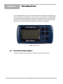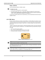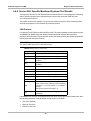
1
R
User Manual
September 2010
EAZ0067L11B Rev. A
Trademarks
Blue Point, MICROSCAN, Scanner, Snap-on, and ShopStream Connect are trademarks of Snap-on Incorporated,
registered in the United States and other countries.
All other marks are trademarks or registered trademarks of their respective holders.
Copyright Information
©2010 Snap-on Incorporated. All rights reserved.
Disclaimer of Warranties and Limitation of Liabilities
The information, specifications and illustrations in this manual are based on the latest information available at the
time of printing. While the authors have taken due care in the preparation of this manual, nothing contained herein:
• Modifies or alters in any way the standard terms and conditions of the purchase, lease, or rental agreement
under the terms of which the equipment to which this manual relates was acquired.
• Increases in any way the liability to the customer or to third parties.
Snap-on reserves the right to make changes at any time without notice.
IMPORTANT:
Before operating or maintaining this unit, please read this manual carefully paying extra attention to the safety
warnings and precautions.
Visit our websites at:
www.diagnostics.snapon.com/microscan (North America)
snapondiag.com (United Kingdom)
sun-diagnostics.com (United Kingdom)
For Technical Assistance Call
1-800-424-7226 (North America)
CALL +44 (0) 845 601 4736 (United Kingdom)
E-mail [email protected] (United Kingdom)
For technical assistance in all other markets, contact your selling agent.
ii
Safety Information
For your own safety and the safety of others, and to prevent damage to the equipment and
vehicles upon which it is used, it is important that these Safety Messages be read and understood
by all persons operating, or coming into contact with, the equipment.
This product is intended for use by properly trained and skilled professional automotive
technicians. The safety messages presented throughout this manual are reminders to the
operator to exercise extreme care when using this test instrument.
There are many variations in procedures, techniques, tools, and parts for servicing vehicles, as
well as in the skill of the individual doing the work. Because of the vast number of test applications
and variations in the products that can be tested with this instrument, we cannot possibly
anticipate or provide advice or safety messages to cover every situation. It is the automotive
technician’s responsibility to be knowledgeable of the system being tested. It is essential to use
proper service methods and test procedures. It is important to perform tests in an appropriate and
acceptable manner that does not endanger your safety, the safety of others in the work area, the
equipment being used, or the vehicle being tested.
It is assumed that the operator has a thorough understanding of vehicle systems before using this
product. Understanding of these system principles and operating theories is necessary for
competent, safe and accurate use of this instrument.
Before using the equipment, always refer to and follow the safety messages and applicable test
procedures provided by the manufacturer of the vehicle or equipment being tested. Use the
equipment only as described in this manual.
Read, understand and follow all safety messages and instructions in this manual, the
accompanying safety manual, and on the test equipment.
Safety Message Conventions
Safety messages are provided to help prevent personal injury and equipment damage. All safety
messages are introduced by a signal word indicating the hazard level.
! DANGER
Indicates an imminently hazardous situation which, if not avoided, will result in death or serious
injury to the operator or to bystanders.
! WARNING
Indicates a potentially hazardous situation which, if not avoided, could result in death or serious
injury to the operator or to bystanders.
! CAUTION
Indicates a potentially hazardous situation which, if not avoided, may result in moderate or minor
injury to the operator or to bystanders.
iii
Safety Information
Important Safety Instructions
Safety messages contain three different type styles.
• Normal type states the hazard.
• Bold type states how to avoid the hazard.
• Italic type states the possible consequences of not avoiding the hazard.
An icon, when present, gives a graphical description of the potential hazard.
Example:
! WARNING
Risk of unexpected vehicle movement.
• Block drive wheels before performing a test with engine running.
A moving vehicle can cause injury.
Important Safety Instructions
For a complete list of safety messages, refer to the accompanying safety manual.
SAVE THESE INSTRUCTIONS
iv
Contents
Safety Information ..................................................................................................................... iii
Contents ...................................................................................................................................... v
Chapter 1: Using This Manual ................................................................................................... 1
Conventions.................................................................................................................................. 1
Bold Text ................................................................................................................................ 1
Terminology ........................................................................................................................... 1
Notes and Important Messages ............................................................................................. 1
Procedures............................................................................................................................. 2
Additional Manuals ....................................................................................................................... 2
Chapter 2: Introduction.............................................................................................................. 3
Functional Description .................................................................................................................. 3
Technical Specifications ............................................................................................................... 5
Control Buttons............................................................................................................................. 6
Y (Accept) Button ................................................................................................................... 6
N (Back) Button...................................................................................................................... 6
Power Button ......................................................................................................................... 6
Up Button ............................................................................................................................... 6
Down Button .......................................................................................................................... 6
Connections.................................................................................................................................. 7
USB Port ................................................................................................................................ 7
Data Cable Connector ........................................................................................................... 7
Power Supply ............................................................................................................................... 7
Vehicle Power ........................................................................................................................ 7
USB Power ............................................................................................................................ 8
Battery Power ........................................................................................................................ 8
Data Cable.................................................................................................................................... 8
Disconnecting MICROCSCAN from the Vehicle .......................................................................... 8
Chapter 3: Getting Started......................................................................................................... 9
Supplying Power........................................................................................................................... 9
Installing the Battery ..................................................................................................................... 9
Connecting to Vehicle Power ..................................................................................................... 10
Auxiliary Power Cables ........................................................................................................ 10
Powering On the Unit ................................................................................................................. 11
Selecting a Language................................................................................................................. 11
Chapter 4: On-Board Diagnostics (OBD) ............................................................................... 12
Global OBD and What it Means ................................................................................................. 12
OBD-II Start-up Phase ......................................................................................................... 12
EOBD Start-up Phase .......................................................................................................... 13
OBD-II/EOBD Limitations ........................................................................................................... 13
OBD-II/EOBD Advantages ......................................................................................................... 13
v
Contents
Communication Protocols........................................................................................................... 13
What is CAN? ...................................................................................................................... 14
Diagnostic Services Introduction ................................................................................................ 14
Readiness Monitor Test Status ............................................................................................ 14
MIL Status ............................................................................................................................ 16
Diagnostic Service Definitions .................................................................................................... 17
Service $01: Display Current Data....................................................................................... 17
Service $02: Powertrain Freeze Frame Data....................................................................... 17
Service $03: Emission-related DTCs ................................................................................... 18
Service $04: Clear/Reset Emission-related Diagnostic Data ............................................... 19
Service $05: Oxygen Sensor Monitoring Test Results......................................................... 20
Service $06: Specific Monitored Systems Test Results....................................................... 24
Service $07: Emission-related DTCs detected during Current or
Last Completed Drive Cycle (Pending Codes)..................................................................... 25
Service $08: On-board Activation Tests............................................................................... 26
Service $09: Vehicle Information ......................................................................................... 26
Service $09: In-use Performance Tracking.......................................................................... 26
Chapter 5: Navigation .............................................................................................................. 28
Screen Layout ............................................................................................................................ 28
Trouble Code Screens................................................................................................................ 28
Menu Screens ............................................................................................................................ 29
Main Menu ........................................................................................................................... 30
Global OBD-2/EOBD Menu.................................................................................................. 30
Exit Menu ............................................................................................................................. 31
Data Screens.............................................................................................................................. 32
Text View ............................................................................................................................. 33
Graph View .......................................................................................................................... 34
Screen Messages....................................................................................................................... 35
Loading and Connecting Messages..................................................................................... 35
Confirmation Messages ....................................................................................................... 35
Warning Messages .............................................................................................................. 36
Error Messages.................................................................................................................... 36
Stopping Vehicle Communication............................................................................................... 36
Chapter 6: Data Parameters .................................................................................................... 37
Long Parameter Names ............................................................................................................. 37
Short Parameter Names ...................................................................................................... 41
DTC Association .................................................................................................................. 45
Chapter 7: Operations.............................................................................................................. 49
Global OBD-2/EOBD .................................................................................................................. 49
Readiness Status ................................................................................................................. 49
Current Data ........................................................................................................................ 50
Freeze Frame Data .............................................................................................................. 50
Confirmed Codes ................................................................................................................. 51
Clear Codes ......................................................................................................................... 51
O2 Monitors ......................................................................................................................... 52
Non-Cont. Monitors .............................................................................................................. 52
Pending Codes .................................................................................................................... 53
vi
Contents
Request Control of On-board System .................................................................................. 53
Vehicle Information .............................................................................................................. 53
Movie .......................................................................................................................................... 54
Settings....................................................................................................................................... 55
Global OBD-2/EOBD Help.......................................................................................................... 55
Select Protocol ........................................................................................................................... 56
Chapter 8: Maintenance ........................................................................................................... 57
Cleaning and Damage Inspection .............................................................................................. 57
Replacing the Battery ................................................................................................................. 57
Storage Tips ............................................................................................................................... 58
Appendix A: Troubleshooting ................................................................................................. 59
Communication Problems .......................................................................................................... 59
Erratic or No Communication ............................................................................................... 59
Testing the Data Link Connector ......................................................................................... 59
Check the Malfunction Indicator Lamp................................................................................. 61
Appendix B: Downloading and Installing Software Updates ............................................... 62
Check for Service Updates Before Use...................................................................................... 62
Verifying Minimum PC Requirements......................................................................................... 62
Verifying PC System Properties........................................................................................... 63
Downloading and Installing ShopStream Connect ..................................................................... 63
Downloading Service Updates ................................................................................................... 65
Before You Begin ................................................................................................................. 66
Installing a Service Update .................................................................................................. 66
Appendix C: Software License Agreement ............................................................................ 69
Appendix D: Product Warranty ............................................................................................... 74
Index .......................................................................................................................................... 75
vii
Chapter 1
Using This Manual
This manual contains tool usage instructions.
Some of the illustrations shown in this manual may contain modules and optional equipment that
are not included on your system. Contact your sales representative for availability of other
modules and optional equipment.
1.1 Conventions
The following conventions are used.
1.1.1 Bold Text
Bold is used in procedures to highlight selectable items such as buttons and menu options.
Example:
• Press the Y button.
1.1.2 Terminology
The term “select” means highlighting a button or menu item using the arrow buttons and pressing
the Y button to confirm the selection.
Example:
• Select Clear Codes.
The above statement abbreviates the following procedure:
1. Scroll with the arrow buttons to highlight Clear Codes on the menu.
2. Press the Y button.
1.1.3 Notes and Important Messages
The following messages are used.
Notes
A NOTE provides helpful information such as additional explanations, tips, and comments.
Example:
1
Using This Manual
i
Additional Manuals
NOTE:
For additional information refer to...
Important
IMPORTANT indicates a situation which, if not avoided, may result in damage to the test
equipment or vehicle.
Example:
IMPORTANT:
The Test ID Table below is for CAN Protocol only.
1.1.4 Procedures
An arrow icon indicates a procedure.
Example:
z
To change screen views:
1. Scroll to highlight Settings on the main menu and press Y to select.
A sub-menu of language options displays.
2. Highlight the desired language and press Y to select.
1.2 Additional Manuals
This tool works in conjunction with other software products. All of the required manuals are
included on the Diagnostics website. See the appropriate manual for information regarding these
products.
2
Chapter 2
Introduction
Your new MICROSCAN™ scan tool provides European On-board Diagnostic (EOBD) trouble
codes and datastream information for electronic vehicle control systems. Your MICROSCAN
can also graph live data parameters, record data, clear diagnostic trouble codes (DTCs) from
the electronic control module (ECM), and reset the vehicle malfunction indicator lamp (MIL).
Contact your sales representative for availability of accessories and upgrades.
Figure 2-1 MICROSCAN
2.1 Functional Description
This section illustrates external features, ports and connectors of the OBD unit.
3
Introduction
Functional Description
1
2
3
4
5
6
7
1— Liquid Crystal Display (LCD) Screen
2— Power Light emitting Diode (LED)
3— Down or Right Button
4— Up or Left Button
5— Y (Yes) Button
6— N (No) Button
7— Power Button
Figure 2-2 Front view
1
1— Battery Cover
Figure 2-3 Back view
1
2
1— USB Port
2— Data Cable Connector
Figure 2-4 Top view
4
Introduction
Technical Specifications
2.2 Technical Specifications
Display:
Liquid Crystal display (LCD) backlight monochrome screen
2.83 inch (72 mm) diagonal
Battery:
9-volt
Dimensions:
Width:
5.53 inch
140.4 mm
Height:
2.68 inch
68 mm
Depth:
1.57 inch
40 mm
Weight:
Without battery:
6.4 ounce
199 g
Operating Temperature Range:
14 to 140°F
–10 to 40°C
Storage Temperature Range:
–4 to 149°F
–20 to 65°C
Data Buffer:
64 data frames (values per parameter)
Communication Protocols:
Your MICROSCAN supports the following OBD-II/EOBD communications protocols:
• SAE J1850 (VPW and PWM)
• ISO 9141-2
• ISO 14230-2 (KWP 2000)
• ISO 15765-4 (CAN)
In addition, the optional vehicle communications software allows you to access “enhanced”
diagnostic information for specific vehicle manufacturers.
5
Introduction
Control Buttons
2.3 Control Buttons
The MICROSCAN has the following control buttons; N (back), Y (accept), b (Up), d (Down),
and Power (Figure 2-2).
2.3.1 Y (Accept) Button
The Y button is used to do the following:
• To select the item that you highlighted using the direction buttons.
• To answer “Yes” when a Yes or No choice is given.
2.3.2 N (Back) Button
The N button is used to do the following:
•
•
•
•
•
To open the Exit Menu
To exit a menu or program.
To close an open list and return to the previous menu.
To answer “No” when a Yes or No choice is given.
To return to the main menu.
2.3.3 Power Button
The Power button powers up the tool, and turns it off.
2.3.4 Up Button
The Up button is used to do the following:
• Move the highlight or cursor up when the screen arrows are vertically aligned.
• Move the highlight or cursor right when the screen arrows are horizontally aligned.
2.3.5 Down Button
The Down button is used to do the following:
• Move the highlight or cursor down when the screen arrows are vertically aligned.
• Move the highlight or cursor left when the screen arrows are horizontally aligned.
6
Introduction
Connections
2.4 Connections
The MICROSCAN scan tool uses two connections; a USB port and a data cable port
(Figure 2-4 on page 4):
2.4.1 USB Port
The USB port is for connecting to a personal computer (PC) and is used for updating the
internal software, and for transferring saved files. The scan tool also receives power through
the USB port when it is connected to a PC.
2.4.2 Data Cable Connector
The data cable connector is used to connect the MICROSCAN scan tool to a vehicle data link
connector (DLC) for testing.
2.5 Power Supply
The MICROSCAN scan tool can receive power from the test vehicle or through the USB port
when connected to a personal computer.
2.5.1 Vehicle Power
Vehicle power is required for the scan tool to properly communicate with the vehicle during
testing. The Data Cable provides power to the unit through the vehicle data link connector
(DLC). The scan tool turns on automatically and checks for stored codes whenever it is
connected to a DLC that provides power.
Two auxiliary power cables are included with MICROSCAN. These cables are used for testing
pre-1996 vehicles without battery power on the diagnostic connector. Refer to “Auxiliary
Power Cables” on page 10 for information on connecting to a test vehicle with these cables.
1
2
1— Battery Power Cable
2— Lighter Power Cable
Figure 2-5 Auxiliary power cables
7
Introduction
Data Cable
2.5.2 USB Power
The MICROSCAN scan tool can be powered by a personal computer (PC) when connected
to the PC with a standard USB cable.
2.5.3 Battery Power
The MICROSCAN scan tool can receive power from the internal 9V battery. Use battery
power to review saved files only.
2.6 Data Cable
A Data Cable is included with your MICROSCAN scan tool. The data cable plugs directly into
the 16-pin data link connector (DLC) on OBD-II vehicles.
2.7 Disconnecting MICROCSCAN from the Vehicle
Always make sure the scan tool is no longer communicating with the vehicle electronic control
module (ECM) before disconnecting the data cable. Opening the data cable connection while
MICROSCAN is actively communicating with the ECM may cause irreversible damage to the
ECM on some models. Refer to “Stopping Vehicle Communication” on page 36 for information
on how to properly end a diagnostic session.
8
Chapter 3
Getting Started
To get started using your new MICROSCAN™ supply power to the tool.
3.1 Supplying Power
There are three ways to supply power to this scan tool:
• Install the battery
• Connect to vehicle power
• Connect to a personal computer (PC) with a USB cable
3.2 Installing the Battery
The MICROSCAN scan tool comes with a 9V battery that installs into a compartment on the
back side of the unit. When replacing the battery, use a heavy-duty type battery from a reliable
manufacturer. Light-duty inexpensive batteries may not provide sufficient power to operate
the scan tool, and may leak and damage your MICROSCAN.
z
To install the battery:
1. Slide the battery cover on the back of the MICROSCAN unit down to release the lock tabs.
2. Pivot the cover up slightly and lift it off of the unit (Figure 3-1).
Figure 3-1 Battery cover removal
3. Connect a new 9-volt battery to the connector and fit the battery into the compartment.
4. Fit the center tab on the battery cover into the slot on the tool housing, pivot the cover
down, and slide it into position so that it locks into place on the housing.
Note the following safety warnings when installing batteries.
9
Getting Started
Connecting to Vehicle Power
! WARNING
Risk of personal injury or harm.
• Always make sure the battery polarities (“+” and “–”) are correct when installing.
• Do not expose batteries to excessive heat.
• Use batteries from a reputable manufacturer only.
• Do not try to recharge batteries that are not specifically designed to be recharged.
• Do not allow children to install batteries unsupervised.
• Follow the battery manufacturer's instructions as to proper handling, storage, and
disposal of batteries.
Improper use of batteries can result in personal harm.
3.3 Connecting to Vehicle Power
The Data Cable, included with your MICROSCAN unit, plugs directly into the data link
connector (DLC) on OBD-II/EOBD vehicles.
z
To connect to vehicle power:
1. Attach the 15-pin connector of the Data Cable to the MICROSCAN unit. Tighten the
captive screws to ensure a good connection.
2. Connect the 16-pin connector of the Data Cable to the DLC of the test vehicle.
3. Switch the vehicle ignition on.
4. The MICROSCAN unit automatically powers on and checks for diagnostic trouble codes
(DTCs) stored in the electronic control module (ECM) of the vehicle.
i
NOTE:
This scan tool can communicate with many non-OBD-II/EOBD vehicles, however, a data
cable adapter and other optional equipment may be needed to connect to the vehicle and to
power the tool. Contact your sales representative for details.
3.3.1 Auxiliary Power Cables
The two auxiliary power cables are included with MICROSCAN are used for testing pre-1996
vehicles without battery power on the diagnostic connector. Optional data cable adapters,
which work with the auxiliary power cables, are also needed to test these earlier vehicles.
IMPORTANT:
The gray colored data cable adapters are designed exclusively for use with MICROSCAN.
Red or black Snap-on adapters for VERUS, MODIS, SOLUS PRO and other Snap-on scan
tools are not compatible with MICROSCAN.
z
To use the auxiliary power cables on OBD-I vehicles:
1. Connect the required test adapter to the data cable.
2. Plug the small end of the Lighter Power Cable into the port on the test adapter.
10
Getting Started
Powering On the Unit
3. Plug the large end of the Lighter Power Cable into the socket of the Battery Power Cable.
4. Connect the clamps of the Battery Power Cable to the vehicle battery. Be sure to observe
correct polarity when connecting to the vehicle battery.
1
2
3
1— Lighter Power Cable, large end
2— Lighter Power Cable, small end
3— Vehicle test adapter
Figure 3-2 Auxiliary power cable connections
3.4 Powering On the Unit
When vehicle power is not available, you can manually power on your MICROSCAN unit
using the internal 9-volt battery. To manually power the tool, Press the Power button on the
front of the unit. Press the Power button on the front of the unit.
3.5 Selecting a Language
English is the default language selection in the scan tool software. However, you can change
the language setting if desired.
z
To change the language setting:
1. Select Settings from the main menu.
2. Select Languages from the settings menu.
3. Scroll to highlight the desired language and press Y.
4. Press N to exit.
The language remains as selected after powering down.
11
Chapter 4
On-Board Diagnostics (OBD)
Your new MICROSCAN conforms to Global OBD (OBD-II in North America and EOBD in Europe)
standards, and is designed for testing compliant vehicles. This chapter describes Global OBD.
4.1 Global OBD and What it Means
Many countries have enacted strict emission related regulations that will drive increased
technology into the modern automobile in order to reduce the exhaust emissions. European and
North American countries lead the way by adopting technology that standardizes the way these
vehicles can be checked for compliance.
The OBD-I (On-Board Diagnostics I) system was introduced in the early 1980s and by 1988 all
new cars and light trucks sold in California had to have OBD-I. The fundamental elements of the
OBD-I are the electrical components (which influence exhaust emissions) that are monitored by
the engine management system. An optical warning signal is given in the event of an OBD-I
relevant failure. This fault can be read out by way of a flashing code.
OBD-II has been compulsory on all vehicles in the US market since January 1996. EOBD
(European On-Board Diagnostics) is the European equivalent to OBD-II. It was introduced in 2000
and became effective in January 2001. There are a few differences between EOBD and OBD-II
but none that will affect scan tool operation. All the communication protocols for both programs are
identical. Vehicle emission strategies and certification procedures vary between countries, states
and regions. Always use service information specific to the country and emission certification.
EURO-3, also known as EOBD, is a continuation of the emission regulations known as EURO-1
and EURO-2. In addition to introducing stricter emission limits, the directive now also covers the
monitoring of emission related components and functions during operation.
The OBD-II and EOBD system must show the failure of an emission related component or system
to the driver using a MIL (Malfunction Indicator).
What does OBD-II and EOBD mean for the Repair Shop?
A universal connector can now be used on any OBD-II 1996 and newer and EOBD 2001 and
newer vehicle, giving the shop more diagnostic coverage that was not previously possible.
4.1.1 OBD-II Start-up Phase
About 40% of the vehicles of model year 1995 sold in the USA were OBD-II prepared. Beginning
in 1996, all vehicles sold in the USA were supposed to comply with OBD-II standards.
However, some 1996 and 1997 vehicles were not fully OBD-II compliant. This means that some
early OBD-II vehicles may:
• Not have the standardized diagnostic connector location or
• Have missing or only partially implemented OBD-II monitors.
12
On-Board Diagnostics (OBD)
OBD-II/EOBD Limitations
4.1.2 EOBD Start-up Phase
The European vehicle manufacturers also needed time to phase in and develop EOBD tests and
software in their electronic control modules (ECMs). Some of the manufacturers already had
experience with the USA OBD-II. Others may still have to improve their most recent software
versions. This means that EOBD is experiencing similar phase in problems as OBD-II, with some
2001 and 2002 vehicles having limited EOBD functionality.
4.2 OBD-II/EOBD Limitations
Generic OBD-II/EOBD data is currently limited to:
• Emission diagnostics or
• Problems related to the Malfunction Indicator.
Access to all available data in the ECM (other systems, other parameters, enhanced diagnostics)
will still require a scan tool with manufacturer specific capabilities.
4.3 OBD-II/EOBD Advantages
The advantage of OBD-II and EOBD is the simple “Plug and Play” function:
• Unlike using a manufacturer specific scan tool or vehicle communication software, one does
not have to select the vehicle make, year or model.
• The communication protocol can be automatically detected by the scan tool software.
• Depending on the ECM and amount of parameters selected, data update rates may vary. By
using functions as Custom Data List and Manual Select PID in Service $01, sometimes data
update rates may be higher than with manufacturer specific software. This can be helpful in
finding intermittent signal gulches.
Data and monitors that are not described in the OBD/EOBD standards are filtered out, although
they are selectable.
4.4 Communication Protocols
A communication protocol is a standardized way of data communication between an ECM and a
scan tool.
For vehicles that comply with OBD-II and EOBD, the following communication protocols are
permitted:
•
•
•
•
ISO 9141-2 (K-LINE)
SAE J1850 PWM (Pulse Width Modulation) and VPW (Variable Pulse Width)
ISO 14230-2 (Keyword Protocol 2000)
ISO 15765-4 (CAN)
The scan tool can be setup so it will automatically determine the communication protocol used in
the vehicle under test.
13
On-Board Diagnostics (OBD)
Diagnostic Services Introduction
4.4.1 What is CAN?
CAN stands for Controller Area Network and means that control units are part of a network and
can interchange data. Although some car manufacturers have used CAN for some years for
communication between electronic control modules (ECMs), it was not directly connected to the
diagnostic connector. In approximately 2001/2002 for Europe and 2003 for North America, the first
car manufacturers started to connect the CAN communication lines to the diagnostic connector.
CAN will be the only required protocol in near future for OBD.
4.5 Diagnostic Services Introduction
The OBD program is divided into several sub programs, called ‘Service $xx’. This complies to the
EOBD/OBD-II standards:
Table 4-1 Diagnostic services
Service
Description
System readiness test status display
$01
MIL (malfunction indicator) Status & Control
Request current powertrain diagnostic data
$02
Request powertrain freeze frame data
$03
Request emission-related DTCs (Diagnostic Trouble
Codes)
$04
Clear/reset emission-related diagnostic data
$05
Oxygen sensor monitoring test results1
$06
Request on-board monitoring test results for specific
monitored systems
$07
Request Pending Codes (emission related
diagnostic trouble codes) detected during current or
last completed driving cycle
$08
Onboard system activation tests
$09
Request vehicle information
$09
In-use Performance Tracking
1. Manual selection of Test IDs is not supported.
4.5.1 Readiness Monitor Test Status
OBD-II/EOBD stipulates the monitoring (continuous or non-continuous) of the functions of the
following emission control related subsystems):
Table 4-2 Continuous or Non-continuous monitors (sheet 1 of 2)
Readiness Monitor
Remark
Misfire monitoring
Continuous
Fuel system monitoring
Continuous
Comprehensive component monitoring
Continuous
† Will only be monitored if the correct conditions are met.
14
On-Board Diagnostics (OBD)
Diagnostic Services Introduction
Table 4-2 Continuous or Non-continuous monitors (sheet 2 of 2)
Readiness Monitor
Remark
Catalyst monitoring
†
Heated catalyst monitoring
†
Evaporative system monitoring
†
Secondary air system monitoring
†
A/C system refrigerant monitoring
†
Oxygen sensor monitoring
†
Oxygen sensor heater monitoring
†
EGR system monitoring
†
† Will only be monitored if the correct conditions are met.
NOTE:
Not all data is applicable or supported by all vehicles.
Each vehicle manufacturer has unique monitor test criteria. The Readiness Test Status indicates
whether a particular diagnostic monitor or function passed its specific test criteria and was found
to be within specification.
EGR, and Purge Monitors
Catalyst, Misfire, EGR, Fuel
Trim, HO2, and Purge Monitors
Misfire, Fuel Trim, and
Purge Monitors
EGR, Fuel Trim, and
Purge Monitors
Misfire, EGR, AIR, Fuel Trim,
HO2, and Purge Monitors
Misfire, Fuel Trim, and
Purge Monitors
Usually the monitors should run and set the Readiness Test Status during normal vehicle
operation. The OBD-II Drive Cycle (see Figure 4-1: ‘Typical OBD-II Drive Cycle’) can be used to
drive the vehicle in a prescribed manner.
HO2 Heater, Misfire,
AIR, Fuel Trim, and
Purge Monitors
i
5 Minutes
3 Minutes
Idle 2.5 Minutes
in Drive, A/C &
Rear Defrost ON
Cold Start
ECT < 50C
Accelerate at 50%
Throttle to 55 mph/
89 kph A/C OFF
Steady State Cruise
55 mph/89 kph
Decelerate to
20 mph/32 kph
with the Clutch
Engaged and
No Brakes
Accelerate at
75% Throttle to
55 to 60 mph/
89 to 97 kph
Steady State Cruise
55 to 60 mph/
89 to 97 kph
Decelerate to
End of Cycle
Without Brakes
Total Time 12 Minutes
Figure 4-1 Typical OBD-II Drive Cycle
As this is a generic drive cycle, it may have limited results on some vehicles. If available, use the
drive cycle information as supplied by the vehicle manufacturer.
System malfunctions that occur later and record a DTC (Diagnostic Trouble Code) will not change
the Readiness Test Status. When the failure is repaired and the DTC is erased, all Readiness Test
Status will be reset to a ‘Not Completed’ status.
15
On-Board Diagnostics (OBD)
Diagnostic Services Introduction
Repair validation
Use the following procedure to validate a repair.
z
To validate the repair:
1. Perform a drive cycle (generic or vehicle specific).
2. Check Service $07 (refer to 4.6.7: ‘Service $07: Emission-related DTCs detected during
Current or Last Completed Drive Cycle (Pending Codes)’ on page 25) and Service $03 (refer
to 4.6.3: ‘Service $03: Emission-related DTCs’ on page 18).
If no DTCs are reported (that relate to the initial failure), it can be assumed that the fault has been
repaired correctly.
4.5.2 MIL Status
Emission related malfunctions set failure specific DTC(s). The MIL (Malfunction Indicator Lamp)
may light up as soon as the first emission related DTC has been stored and confirmed (stored a
second time). Depending on the type of malfunction, it may take multiple drive cycles before the
MIL turns on.
The MIL is located in the instrument panel. The MIL may display a symbol of an engine and should
light up as soon as the ignition is switched on. Three different states are possible when the engine
is running:
1. OFF: no emission limits exceeded.
2. ON: at least one OBD-II/EOBD emission limit exceeded.
3. Blinking: possibility of damage to the catalytic converter.
Figure 4-2 Example of Malfunction Indicator Lamp
i
NOTE:
The MIL may also be called the “Check Engine” lamp.
The ECM transmits the status of the Malfunction Indicator including the identification of the ECM
that commanded the MIL to turn on.
i
NOTE:
The MIL status indicates “off” during the ignition key on, engine off instrument panel bulb check
unless the MIL has been commanded “on” for a detected malfunction.
16
On-Board Diagnostics (OBD)
Diagnostic Service Definitions
4.6 Diagnostic Service Definitions
4.6.1 Service $01: Display Current Data
The ECMs transmit the data value stored by the system. The data is commonly called PID
(Parameter IDentification). All of the sensors parameters show the actual readings. Not default or
substitute values used by the system, because of a fault with that sensor.
Depending on the ECM and amount of parameters selected, data update rates may vary. Use
Custom Data List to select the parameters to be displayed in Service $01. The fewer data
parameters were selected, the faster the update rate.
Only OBD/EOBD defined parameters appear in the Current Data List. To view not supported
parameters, select Manual Select PID (the last item of the Current Data List).
4.6.2 Service $02: Powertrain Freeze Frame Data
Engine conditions are stored by the ECM at the time a Monitor detects an emission-related fault.
A “Freeze Frame” is such a group of captured information.
Using Freeze Frame for Diagnostic Purposes
Freeze Frame is useful for determining the exact conditions the vehicle was operating under when
the DTC was set.
i
NOTE:
Freeze Frame is captured and stored when the DTC is set, not when the problem began.
For example, misfire is evaluated every 1000 rpm. A misfire DTC may be stored 60 to 90 seconds
after the misfire initially occurred, at substantially different speed and load conditions.
The Technician can duplicate these conditions to verify the complaint or the repair. In some cases
the on-board tests for a specific DTC may report no problem found. But when the conditions match
the Freeze Frame conditions, that same DTC would set with the MIL on.
i
NOTE:
Freeze Frame data is erased whenever codes are cleared.
Does a stored DTC change?
It can be overwritten by higher priority Emission DTCs. Misfire and Fuel System DTCs have the
highest priority. A lower rated DTC may be overwritten by a higher priority DTC.
Only data parameters supported by the ECM are included in the Freeze Frame data list.
17
On-Board Diagnostics (OBD)
Diagnostic Service Definitions
4.6.3 Service $03: Emission-related DTCs
The purpose of this service is to enable the scan tool to obtain stored DTCs from the power train
ECMs that are emission-related.
The OBD-I ECM primarily identifies a faulty signal or a faulty sensor using three steps:
• Signal or component shorted to ground
• Signal or component shorted to battery positive
• No signal or component (open circuit)
For each of these tests, a specific trouble code is set.
With OBD-II/EOBD, expanded diagnostics now includes “rationality” testing. One input signal is
compared against other input signals to determine if the reading is reasonable, given the current
operating conditions.
Table 4-3 Diagnostic Trouble Code description
Position
Description
P = Power train
1
C = Chassis
B = Body
U = Network
0 = Standardized emission-related trouble code
2
1 = Manufacturer-specific trouble code
2 = Standardized or Manufacturer-specific trouble code
3 = Standardized or Manufacturer-specific trouble code
0 = Overall system
1 = Secondary air system/Mixture preparation
2 = Fuel system
3 = Ignition system/Misfires
4 = Additional exhaust gas monitoring
3
5 = Cruise control/Idle speed control
6 = Input/Output signals, Control units
7 = Gearbox/Transmission
8 = Transmission
9 = Transmission
A = Hybrid Propulsion
B = Reserved
4&5
Serial numbering of individual components or systems
18
On-Board Diagnostics (OBD)
Diagnostic Service Definitions
P0 237
Position 4 & 5
Position 3
Position 2
Position 1
Figure 4-3 Example: DTC “P0237”
In this example, definitions listed for Position 3 are only valid for DTCs starting with “P”. For other
codes (C, B, U) there are other definitions. Please refer to ruling OBD standards for more
information.
Code Ranking
OBD-II/EOBD Codes have a priority according to their emission severity, with higher priority codes
overwriting lower priority codes. The priority of the code determines the illumination of the MIL and
the code erase procedure.
Vehicle manufacturers have implemented the ranking differently.
4.6.4 Service $04: Clear/Reset Emission-related Diagnostic Data
i
NOTE:
It is recommended to perform the Clear Code/Reset function with the engine off and the ignition
switched on.
The purpose of this service is to clear codes and turn off the MIL. It is recommended to print the
DTCs before erasing them, for comparison after repairs are made.
Clearing the code memory erases all diagnostic information stated in “Reset Information” below:
Table 4-4 Reset Information (sheet 1 of 2)
Service
Items to reset
Status of system monitoring tests
Number of diagnostic trouble codes
Distance travelled while MIL is activated
$01
Number of warm-ups since DTCs cleared
Distance travelled since DTCs cleared
Time run by the engine while MIL is activated
Time since diagnostic trouble codes cleared
$02
Diagnostic trouble code for freeze frame data
Freeze frame data
19
On-Board Diagnostics (OBD)
Diagnostic Service Definitions
Table 4-4 Reset Information (sheet 2 of 2)
Service
Items to reset
$03
Confirmed diagnostic trouble codes
$05
Oxygen sensor test data
$06
Specific on-board monitoring test results
$07
Pending diagnostic trouble codes
The following may occur as well:
• It may also erase engine management adaptive memory (some vehicle manufacturers only)
when codes are cleared. Depending on the vehicle, adaptive memory may not correct itself
without extensive driving.
• Other manufacturer specific actions for clearing and setting may also occur in response to this
request message.
• Normally the MIL automatically turns off after a successful repair, if emissions are normal.
Refer to “Repair validation” on page 16.
IMPORTANT:
For safety and/or technical design reasons, some ECMs may not respond to this service under all
conditions.
i
NOTE:
In most cases, once a MIL is deactivated, the original code remains in memory until forty to eighty
warm-up cycles are completed without the fault reappearing.
4.6.5 Service $05: Oxygen Sensor Monitoring Test Results
The purpose of this service is to allow access to the on-board oxygen sensor monitoring test
results (if implemented).
i
NOTE:
For CAN vehicles, Service $05 is not supported. Oxygen sensor test results are implemented in
Service $06. For non-CAN vehicles, manufacturers can use Service $06 as an alternative to
Service $05.
Different manufacturers may use many methods to calculate test results for this service. The scan
tool converts test values and displays them in the standard units of measurement.
The ECM transmits the latest test results available from the system. Test results are retained by
the ECM, even over multiple ignition OFF cycles, until replaced by the results of a more recent
test. Test results are requested by Test ID. (See Test ID Table).
Test results can be reported either as a constant or as a calculated value, depending on the Test
ID. Calculated values are reported with minimum and maximum limits.
i
NOTE:
Depending on the manufacturer, calculated values may be rounded off, which means that a test
may fail despite the values reading within min. and max limits.
20
On-Board Diagnostics (OBD)
Diagnostic Service Definitions
The scan tool checks if the readiness status of oxygen sensors is completed. If the test is not
completed, the scan tool displays a warning.
$08
Oxygen
Sensor
Output
$04
Rich
$01
$02
$03
$07
Lean
Numbers Refer to Test ID
$06
$05
$0A
$09
Figure 4-4 Test ID Values Example
i
NOTE:
Refer to Table 4-5 for an explanation of the individual Test ID numbers.
Table 4-5 Test ID Table
Test ID No.
$01
i
Description
Rich to Lean sensor threshold voltage (constant)
$02
Lean to Rich sensor threshold voltage (constant)
$03
Low sensor voltage for switch time calculation
(constant)
$04
High sensor voltage for switch time calculation
(constant)
$05
Rich to Lean sensor switch time (calculated)
$06
Lean to Rich sensor switch time (calculated)
$07
Minimum sensor voltage for test cycle (calculated)
$08
Maximum sensor voltage for test cycle (calculated)
$09
Time between sensor transitions (calculated)
$0A
Sensor Period (calculated)
$0B
EWMA (Exponential Weighted Moving Average)
misfire counts for last 10 driving cycles (calculated)
Calculation: 0.1 * (current counts) + 0.9 * (previous
average)
Initial value for (previous average) = 0
$0C
Misfire counts for last/current driving cycles
(calculated)
NOTE:
Not all test values are applied on or supported by all vehicles. Only supported Test IDs appear in
the selection list.
21
On-Board Diagnostics (OBD)
Diagnostic Service Definitions
Cylinder Bank & O2S Locations, Examples
1
2
3
4
Figure 4-5 L4 Cylinder Engine with 1 exhaust bank and 1 Catalyst
1— Engine, exhaust bank
2— Sensor 1
3— Catalyst
4— Sensor 2, (heated)
1
2
3
4
5
Figure 4-6 L4 Cylinder Engine with 1 exhaust bank and 2 Catalysts
1— Engine, exhaust bank
2— Sensor 1
3— Catalyst
4— Sensor 2, (heated), Bank 1
5— Catalyst
6— Sensor 3 (heated), Bank 1
22
6
On-Board Diagnostics (OBD)
Diagnostic Service Definitions
1A
2A
3A
4A
2B
3B
4B
5
6
V
1B
Figure 4-7 V8 Cylinder Engine with 2 exhaust banks and 3 Catalysts
1— Exhaust Bank X
2— Sensor 1, Bank X
3— Catalyst
4— Sensor 2, (heated), Bank X
5— Catalyst
6— Sensor 3 (heated), Bank X
1A
2A
3A
4A
5A
6A
2B
3B
4B
5B
6B
V
1B
Figure 4-8 V8 Cylinder Engine with 2 exhaust banks and 4 Catalysts
1— Exhaust Bank X
2— Sensor 1, Bank X
3— Catalyst
4— Sensor 2, (heated), Bank X
5— Catalyst
6— Sensor 3 (heated), Bank X
23
On-Board Diagnostics (OBD)
Diagnostic Service Definitions
4.6.6 Service $06: Specific Monitored Systems Test Results
The purpose of this service is to allow access to the test results for on-board diagnostic monitoring
tests of specific components or systems that are continuously monitored (CAN only) and
non-continously monitored.
The misfire monitor is an example of a continuously monitored system, and the catalyst system
would be an example of a non-continously monitored system.
CAN Protocol
For CAN the Test ID Table from Service $05 is used. The request message for test values includes
an OBDMID (On-Board Diagnostic Monitor IDentification) that indicates the information
requested. Unit information is given with the values. Test values (results) are always reported with
the minimum and maximum test limits.
IMPORTANT:
The Test ID Table below is for CAN Protocol only:
Table 4-6 Test ID Table for CAN Protocol
Test ID No.
Description
$01
Rich to Lean sensor threshold voltage, (Constant)
$02
Lean to Rich sensor threshold voltage, (Constant)
$03
Low sensor voltage for switch time calculation,
(Constant)
$04
High sensor voltage for switch time calculation,
(Constant)
$05
Rich to Lean sensor switch time, (Calculated)
$06
Lean to Rich sensor switch time, (Calculated)
$07
Minimum sensor voltage for test cycle, (Calculated)
$08
Maximum sensor voltage for test cycle, (Calculated)
$09
Time between sensor transitions, (Calculated)
$0A
Sensor Period, (Calculated)
$0B
EWMA (Exponential Weighted Moving Average)
misfire counts for last 10 driving cycles (calculated)
Calculation: 0.1 * (current counts) + 0.9 * (previous
average)
Initial value for (previous average) = 0
$0C
Misfire counts for last/current driving cycles
(calculated)
If an OBDMID has not been completed at least once since Service $04 or battery disconnect, then
the following properties of the parameter are set to zero by the ECM:
• Test Value (Results)
• Minimum Test Limit
• Maximum Test Limit
24
On-Board Diagnostics (OBD)
Diagnostic Service Definitions
Non CAN Protocol
The vehicle manufacturer is responsible for assigning Test IDs and Component IDs for tests of
different systems and components. The latest test results are to be retained, even over multiple
ignition OFF cycles, until replaced by more recent test results. Test results are requested by Test
ID. Test results are reported only for supported combinations of test limit type and component ID
and are reported as positive (unassigned) values. Service $06 test values and limits are raw
values that not scaled.
To date, only some manufacturers have provided conversion factors for technicians to use this
data. See the example below for a US Ford version of Service $06 Catalytic Converter test results.
Table 4-7 Service $06 Catalytic Converter test results
Test ID
Comp ID
Test
$10
$11
Cat monitor Switch ratio
Bank1
$10
$21
Cat monitor Switch ratio
Bank2
Value Min. Max
45
0
48
42
0
48
Ford conversion factor: multiply the value by 0.0156 to get a value from 0 to 1.0.
Table 4-8 Calculated values
Item
Factor
Result
Bank 1
45 * 0.0156
0.702
Bank 2
42 * 0.0156
0.655
Threshold
48 * 0.0156
0.749
This catalyst is about to fail. Normal readings for a good catalyst should be approximately
0 to 0.1 (switch ratio).
Service $06 Notes
Consider the following when performing this service:
• If in Service $01 (Readiness Test Status) one of the tests is not completed, a warning
message displays indicating that the values may be invalid or not available.
• Not all test values are applicable or supported by all vehicles. Only supported Test IDs appear
on the selection list. To be able to select none supported Test IDs, the last item of the selection
list is Manual Selection of Test ID.
• This service can be used as an alternative to Service $05 to report oxygen sensor test results
The values are not converted and are displayed in standard units.
4.6.7 Service $07: Emission-related DTCs detected during Current or
Last Completed Drive Cycle (Pending Codes)
The purpose of this service is to enable the scan tool to obtain “pending” or maturing diagnostic
trouble codes. These are codes for emission-related components or systems that are tested or
continuously monitored during normal driving conditions that were detected during the current or
last completed driving cycle.
25
On-Board Diagnostics (OBD)
Diagnostic Service Definitions
Test results for these components or systems are reported in the same format as the DTCs in
Service $03; refer to “Service $03: Emission-related DTCs” on page 18.
The intended use of this service is to assist the service technician after a vehicle repair and after
clearing diagnostic information, by reporting test results after a single driving cycle.
• If a test failed during the driving cycle, the DTC associated with that test will be reported. If the
pending fault does not occur again within 40 to 80 warm-up cycles, the fault is automatically
cleared from memory.
• Test results reported by this service do not necessarily indicate a faulty component or system.
If test results indicate a failure again after additional driving, then a DTC will set with Service
$03, indicating a faulty component or system. The MIL will be illuminated.
This service can always be used to request the results of the latest test, independent of the setting
of a DTC.
4.6.8 Service $08: On-board Activation Tests
This service controls the operation of vehicle components, tests or systems. These tests are also
known as “On-Board Activation Tests”.
4.6.9 Service $09: Vehicle Information
The purpose of this service is to enable the scan tool to request vehicle specific vehicle
information such as:
• Vehicle Identification Number (VIN)
• Calibration IDs
• Calibration Verification Numbers (CVN, displayed as hexadecimal value)
Some of this information may be required by regulations and some may be desirable to be
reported in a standard format, if supported by the vehicle manufacturer.
4.6.10 Service $09: In-use Performance Tracking
This data is used to support possible regulatory requirements for “In-use Performance Tracking”.
Manufacturers are required to implement software programs that track in-use performance for
each of the following components or systems:
•
•
•
•
•
•
•
Catalyst Bank 1
Catalyst Bank 2
Primary Oxygen Sensor Bank 1
Primary Oxygen Sensor Bank 2
Evaporative Leak Detection System
EGR System
Secondary Air System
26
On-Board Diagnostics (OBD)
Diagnostic Service Definitions
The completion value tracks the number of times that all conditions necessary for a specific
monitor to detect a malfunction have been encountered. The condition value indicates the number
of times that the vehicle has been operated in the specified conditions.
OBD Monitoring Conditions—displays the number of times that the vehicle has been operated
in the specified OBD monitoring conditions.
Engine Starts—displays the count of the number of times that the engine has been started.
Catalyst Monitor Completion Bank X—displays the number of times that all conditions
necessary to detect a Catalyst System Bank 1 or 2 malfunction have been encountered.
Catalyst Monitor Conditions Bank X—displays the number of times that the vehicle has been
operated in the specified Catalyst monitoring conditions.
O2 Sensor Monitor Completion Bank X—displays the number of time that all conditions
necessary to detect an Oxygen Sensor Bank 1 or 2 malfunction have been encountered.
O2 Sensor Monitor Conditions Bank X—displays the number of times that the vehicle has been
operated in the specified Oxygen Sensor monitoring conditions.
EGR Monitor Completion—displays the number of time that all conditions necessary to detect
an EGR system malfunction have been encountered.
EGR Monitor Conditions—displays the number of times that the vehicle has been operated in
the specified EGR system monitoring conditions.
Secondary Air Monitor Completion—displays the number of time that all conditions necessary
to detect a Secondary Air system malfunction have been encountered.
Secondary Air Monitor Conditions—displays the number of times that the vehicle has been
operated in the specified Secondary Air system monitoring conditions.
EVAP Monitor Completion—displays the number of time that all conditions necessary to detect
an EVAP system leak malfunction have been encountered.
EVAP Monitor Conditions—displays the number of times that the vehicle has been operated in
the specified EVAP system leak malfunction monitoring conditions.
27
Chapter 5
Navigation
The following sections describe screen layout, how to navigate the interface, and how to make
selections using screen menus and buttons. The various types of screen messages are also
explained in this section.
5.1 Screen Layout
MICROSCAN™ display screens typically consist of two sections:
1
2
LIVE DATA
ID:$
RPM(1/min.)
TPS(%)
IAT(°C)
ECT(°C)
A/F Rate(g/s)
11
1800
50.2
88
104
11.52
Figure 5-1 Sample screen
1— Title bar—shows the type of test being performed and the power source
2— Main body—shows test data
One of three basic types of screen displays for most scan tool procedures:
• Trouble code screens
• Menu screens
• Data screens
Each type is explained below.
5.2 Trouble Code Screens
A trouble code screen displays a list of the diagnostic trouble codes (DTCs) stored in the
electronic control module (ECM) of the test vehicle. The MICROSCAN automatically tests for
codes on connection to a vehicle data link connector (DLC) on power up. An “establishing
communication” message momentarily displays on the screen while the MICROSCAN gathers
code information. A “No Codes” message displays if there are no stored DTCs in the vehicle ECM.
If there are stored codes, a code report similar to the example shown below displays. An arrow
head in the lower right corner of the screen indicates there are additional codes, scroll with the
down (d) button to view the entire list.
28
Navigation
Menu Screens
TROUBLE CODES
Confirmed Codes
P0105
Intake (A) Camshaft Posit...
P0115
Engine Coolant Temperatu...
Figure 5-2 Sample code report
A sub-title, which can read Confirmed Codes, Pending Codes, or Permanent Codes, appears at
the top of the report. The sub-title changes as you scroll through the list if there are more than one
type of code in memory. Codes are listed in ascending order with a truncated description on the
line immediately below the DTC. Press Y and a window showing the complete description of the
highlighted DTC opens.
TROUBLE CODES
Confirmed Codes
P0128: Coolant
P0128
Thermostat
(Coolant Temp
Coolant
Thermostat...
Below Thermostat
P0115
Regulating
Temperature).
Coolant
Thermostat
(Coola...
Figure 5-3 Sample DTC description window
IMPORTANT:
Certain “Enhanced Codes”, which are specific to a particular manufacturer, do not display in the
standard code list that automatically opens when connected to a vehicle. Select Enhanced Codes
from the main menu to view these manufacturer specific DTCs.
5.3 Menu Screens
Menu screens present a list of options from which you can select. Selecting a menu option can
open a test, perform a function, or open a sub-menu of additional choices. A typical “main menu”
is shown below.
MAIN MENU
Global OBD-2/EOBD
Enhanced Codes
Captured Movies
Settings
Global OBD-2/EOBD Help
Select Protocol
Figure 5-4 Sample main menu
29
Navigation
Menu Screens
z
To select from a menu:
1. Use the up (b) and down (d) buttons to move the highlight to the desired choice.
2. Press Y to make the selection.
5.3.1 Main Menu
The main menu is the default screen that displays under the following conditions:
• The MICROSCAN unit is turned on and powered by the internal battery.
• The MICROSCAN unit is powered by the vehicle but cannot establish communication with the
vehicle ECM.
• When exiting from a Trouble Codes screen.
• When Y is selected from a “No Codes” screen.
The main menu may include the following options:
• Global OBD-2/EOBD—opens a sub-menu of test options.
• Enhanced Codes (optional)—the MICROSCAN Pro or MICROSCAN Standard with optional
software can access enhanced engine codes. Selecting this option opens a list of
manufacturer specific codes in memory that are not included in the standard DTC list.
•
•
•
•
•
Movie—opens a previously recorded data file.
Settings—opens a menu for configuring the MICROSCAN display characteristics.
Global OBD-2/EOBD Help—opens a “help” file that explains certain global OBD tests.
Select Protocol—allows you to choose which communication protocol the scan tool uses.
OBD-I Codes (optional)—MICROSCAN Pro or MICROSCAN Standard with optional software
can access OBD-I codes on select pre-1996 GM, Ford, Chrysler and Toyota vehicles.
Optional adapters are needed, contact your selling agent for details.
• ABS Codes (optional)—MICROSCAN Pro or MICROSCAN Standard with the optional
software displays codes for the antilock brake systems (ABS) on select GM, Ford and
Chrysler vehicles.
5.3.2 Global OBD-2/EOBD Menu
The Global OBD2/EOBD menu presents a list of standard tests from which you can choose.
GLOBAL OBD-2/EOBD
Current Data
Freeze Frame Data
Confirmed Codes
Clear Codes
O2 Monitors
Non-Cont. Monitors
Figure 5-5 Sample Global OBD-2/EOBD menu
30
Navigation
Menu Screens
A brief description of each test is presented here, more detailed descriptions can be found in the
Operations Chapter of this manual.
•
•
•
•
•
•
•
Current Data—displays “live” data parameter values transmitted by the vehicle ECM.
Extended Data (Optional)—displays additional data values not included on the standard list.
Freeze Frame Data—displays certain data values that were captured when a DTC set.
Confirmed Codes—displays any emissions related DTCs stored in ECM memory.
Clear Codes—erases DTC and freeze frame records from ECM memory.
O2 Monitors—displays the status of the oxygen (O2) sensor monitors.
Non-Cont. Monitors—displays the status of the non-continuous monitors.
5.3.3 Exit Menu
The exit menu opens as a “pop-up” when the N button is pressed from most screens and offers a
series of functions to choose from. The pop-up presents graphic representations for three
functions and the center option is the one that is activated if the Y button is pressed.
Table 5-1 Exit menu graphic definitions (sheet 1 of 2)
Name
Graphic
Protocol Information
Description
Shows the current communication
protocol, the number of emissions
related DTCs, and the serial number of
your MICROSCAN unit.
Returns to the previous screen, this is
the default selection for the exit menu.
Exit
Opens a menu for configuring the
MICROSCAN display, this is the
Settings
same as the Settings selection from the
main menu.
Screen Capture
Saves a copy of the last screen viewed
before the N button was pressed.
Save Movie
Saves a copy of the data recorded in
the data buffer.
Lock/Unlock
Locks or unlocks the parameter
highlighted on the previous screen to
either prevent or allow it to scroll.
Text/Graph
Switches the data list between a text
view and a graph view.
Min/Max
Recalibrates the minimum and
maximum data values displayed on a
data graph.
31
Navigation
Data Screens
Table 5-1 Exit menu graphic definitions (sheet 2 of 2)
Name
Graphic
Pause/Play
Description
Suspends data collection when viewing
live data to allow closer examination,
and restarts data collection when
viewing paused data.
Clear ECM Memory
Erases all data, stored codes, pending
codes, and freeze frame information,
from the vehicle ECM.
Custom Data List
Allows you to select which data
parameters display on the data list.
The up (b) and down (d) buttons scroll the graphics right and left respectively when more than
three options are available. The graphics scroll in a continuous loop so there is no need to reverse
direction while scrolling.
z
To use the Exit menu:
1. Press the N button to open the menu.
GLOBAL OBD-2/EOBD
Current Data
Freeze Frame Data
Confirmed Codes
Clear Codes
O2 Monitors
Non-Cont. Monitors
Figure 5-6 Sample Exit menu
2. Press the up (b) button to scroll left or the down (d) button to scroll right until the desired
option is in the center position.
3. Press the Y button to activate the selected function.
5.4 Data Screens
Data screens display serial datastream parameter values, which represent input and output
information that the ECM is receiving and transmitting to the various actuators, sensors, and
switches in the electronic control system.
Vehicle datastream information can be displayed in two formats; text view and graph view. Use the
Text/Graph function on the Exit menu to switch between viewing modes.
32
Navigation
Data Screens
5.4.1 Text View
Text view screens include a parameter description and a parameter value. The units of the value,
such as V for volts, mS for milliseconds, and % for percent, are shown in parenthesis after the
parameter description. A lock icon appears to the right of the value if the parameter has been
locked to prevent it from scrolling. Up and down scroll arrows appear to the right of the values
whenever additional parameters are above and below those shown on the current screen.
i
NOTE:
Parameters display in the order in which they are transmitted by the ECM. Therefore, the display
order can vary considerably depending upon make, model, and year.
1
2
3
LIVE DATA
RPM(1/min.)
TPS(%)
TPS(V)
IAT(°C)
ECT(°C)
A/F Rate(g/s)
4
1800
50.2
2.7
88
104
11.52
5
5
1— Parameter description
2— Parameter value unit
3— Parameter value
4— Lock icon
5— Scroll arrows
Figure 5-7 Sample text view screen
Up to three parameters can be locked in place to allow side-by-side comparison while in the text
view. Use the Lock/Unlock function on the Exit menu to lock and release parameters. When a
parameter is locked, it is moved to the top of the data list, when it is released it returns to its original
position in the data list.
An abbreviated, or short version, of the parameter description is used so that it fits on one line.
Highlight a parameter and press Y to open a pop-up with the complete long parameter name.
LIVE DATA
RPM(1/min.)
ECT: Engine Coolant
TPS(%)
TPS(V)
Temperature (°C)
IAT(°C)
ECT(°C)
A/F Rate(g/s)
1800
50.2
2.7
88
104
11.52
Figure 5-8 Sample long parameter name pop-up
33
Navigation
Data Screens
5.4.2 Graph View
Graph view screens include a parameter description and a data graph parameter value activity.
The units of the data value, the lock icon, and the scroll arrows are similar as for text view. The
short parameter name is shown, but pressing Y opens a pop-up to reveal the complete name. Due
to the height of the data graphs, only two parameters are displayed at a time and only one
parameter can be locked. A parameter moves to the top of the data list when it is locked. If more
than on parameter was locked when graph view is selected, the top parameter in the list remains
locked and the others return to their original positions in the data list.
1 2
3
4
5
LIVE DATA
RPM(1/min.)
1850
TPS(%)
50.2
6
6
1— Parameter description
2— Current data value
3— Parameter value unit
4— Parameter data graph
5— Lock icon
6— Scroll arrows
Figure 5-9 Sample graph view screen
The MICROSCAN constructs the graphs from left to right across the screen and generates a point
on the graph for each data stream transmission from the ECM. How quickly the graph area of the
screen is filled depends upon the transmission speed of the ECM, so expect graphing speed
differences between makes and models. The screen is wide enough to display 64 data points on
a graph. Once the graph fills the screen older point at the left edge are hidden as new points on
the right edge are added. The value of the current sample point displays below the parameter
name alongside the graph.
A special cursor function that allows you to scroll across the data graphs is available on the exit
menu in graph view. When selected a cursor appears as a vertical line on the graphs, arrows on
either side of the graph show the scrolling direction has changed, and a frame counter the show
the relative position of the cursor displays in the title bar. The sampled value at the point of the
cursor displays below the parameter description.
34
Navigation
Screen Messages
1
LIVE DATA
2
28 64
RPM(1/min.)
1225
TPS(%)
23.7
1— Cursor
2— Frame counter
Figure 5-10 Sample graph with cursor
IMPORTANT:
You cannot scroll up and down through the data list in cursor mode. Make sure the two parameters
you want to examine are on the screen before selecting the cursor mode.
5.5 Screen Messages
There are four types of on-screen messages:
•
•
•
•
Loading and connecting
Confirmations
Warnings
Errors
5.5.1 Loading and Connecting Messages
Loading and connecting messages display when the MICROSCAN unit is performing an internal
operation, such as loading a database, initiating a test, or establishing communications with the
vehicle. The message automatically clears once the internal operation is complete.
5.5.2 Confirmation Messages
Confirmation messages inform you when you are about to perform an action that cannot be
reversed or when an action that requires your confirmation to continue has been initiated.
When a response is not required, the message displays briefly before disappearing.
35
Navigation
Stopping Vehicle Communication
5.5.3 Warning Messages
Warning messages inform you when completing the selected action may result in an irreversible
change or loss of data.
5.5.4 Error Messages
Error messages inform you when a system or procedural error has occurred. Examples of
possible errors include a disconnected cable, a poor connection, or some other mechanical failure
that prevents the tool from communicating with the vehicle.
5.6 Stopping Vehicle Communication
Disconnecting the MICROSCAN unit from the data link connector (DLC) while it is actively
communicating with the vehicle may cause electronic control module (ECM) damage on some
models. Always follow the procedure below while viewing live data to end the diagnostic session
before separating the data cable from the DLC.
z
To stop communications and disconnect from the vehicle:
1. Press the N button from any data screen.
The Exit menu opens.
2. Scroll to highlight the Exit icon on the menu.
GLOBAL OBD-2/EOBD
Current Data
Freeze Frame Data
Confirmed Codes
Clear Codes
O2 Monitors
Non-Cont. Monitors
Figure 5-11 Sample highlighted Exit icon
3. Press Y to select exit.
The display returns to the Global OBD2/EOBD menu.
4. Press N once again to open the Exit menu.
5. Again, highlight the Exit icon on the menu.
6. Press Y to select exit.
A “stop communications” message momentarily displays followed by the Main menu. The
message indicates that the electronic connection between the MICROSCAN unit and the
ECM has been terminated. To verify, open the Exit menu. The Exit icon should no longer be
available as a menu option.
7. From the Main menu, press the Power button to shut down the MICROSCAN unit.
8. Disconnect the data cable from the vehicle DLC.
36
Data Parameters
Chapter 6
Mode $01 and $02 services involve evaluating the vehicle data stream parameter values. This
section provides definitions for the values that display on the viewing screen, along with diagnostic
tips. The information is presented in three ways:
• “Long parameter names” on page 37—lists parameters by their complete names
• “Short parameter names” on page 41—lists parameters by their common acronym
• “DTC association” on page 45—lists parameter names by their corresponding diagnostic
trouble code (DTC)
Depending upon the vehicle being tested and other variables, the screen may display either the
long or short parameter names on the data list. The numeric definitions are based on the last three
characters of the diagnostic trouble code. Refer to “Service $03: Emission-related DTCs” on
page 18 information on DTC structure.
6.1 Long Parameter Names
Table 6-1 lists data parameter definitions alphabetically by their complete name. The complete
name typically displays when viewing data in text mode.
i
NOTE:
Counters (like cylinder bank or sensor position) in a parameter name are represented by a ‘y’ or
‘x’ in the table.
The vehicle ECM determines the parameter data list, not all parameters display on every vehicle.
Table 6-1 Long parameter names (sheet 1 of 4)
Parameter
Description for long parameter
ABSOLUTE LOAD VALUE
Value is presented as a percentage and ranges from 0 to 100 for
naturally aspirated engines, and from 0 to 400 for boosted
engines.
On boosted engines the actual figure displayed is very much
depending on how much boost is used. The higher the boost used,
the higher Absolute Load Value will be.
ABSOLUTE THROTTLE
POSITION–/B/C
Shows the absolute throttle position. The output signal is a
proportional percentage to the input voltage (when proportional) or
100% minus the proportional percentage (when inversely
proportional).
See PID $45 for the relative position.
ACCELERATOR PEDAL
POSITION x
Shows the absolute pedal position. The output signal is a
proportional percentage to the input voltage (when proportional) or
100% minus the proportional percentage (when inversely
proportional).
AIR FLOW RATE
Shows the flow rate of the intake air as measured by the Mass Air
Flow (MAF) sensor.
37
Data Parameters
Long Parameter Names
Table 6-1 Long parameter names (sheet 2 of 4)
Parameter
Description for long parameter
AMBIENT AIR
TEMPERATURE
Can be obtained from an AAT sensor directly or deducted by the
ECM from other sensor signals.
BAROMETRIC PRESSURE
Can be obtained from a BARO or MAP sensor directly or deducted
by the ECM from other sensor (MAF) signals. If the value at
'ignition key on' and certain driving conditions is stored into a
memory, clearing the memory may lead to inaccurate BARO
values.
The ECM calculates the engine load by dividing the actual
manifold airflow volume (Otto engines) or actual fuel flow (Diesel
engines) by the maximum possible volume with a factor for
CALCULATED LOAD VALUE
pressure and temperature compensation. Correlates with the
engine vacuum. Value is presented as a percentage and ranges
from 0 to 100.
CATALYST TEMPERATURE
Bx–Sy
Shows the catalyst substrate temperature for the mentioned bank
or the temperature of the mentioned bank and oxygen sensor. Can
be obtained from a sensor directly or deducted by the ECM from
other sensor signals.
COMMANDED EGR
Shows the status of the Exhaust Gas Recirculation system
between 0% (no flow) and 100% (max. flow, max. duty cycle)
COMMANDED
EQUIVALENCE RATIO
Shows the Air/Fuel ratio as commanded by the ECM. To obtain the
actual Air/Fuel ratio, multiply the stoichiometric Air/Fuel ratio by the
equivalence ratio. Conventional oxygen sensors shows the ratio
when in Open Loop only. In Closed Loop '1.0' is shown. Wide
range, or linear, oxygen sensors show the ratio in Open Loop and
Closed Loop.
COMMANDED
EVAPORATIVE PURGE
Shows the status of the Evaporative Purge Control Valve between
0% (no flow) and 100% (max. flow, max. duty cycle)
COMMANDED SEC. AIR
STATUS
Shows the position of the Secondary Air system (upstream or
downstream of the first catalytic converter) and/or its status.
COMMANDED THROTTLE
ACT.CONTROL
Shows the status of the Throttle Actuator Control between 0%
(closed throttle) and 100% (wide open throttle)
CONTROL MODULE
VOLTAGE
Shows the power input to the ECM. This is not automatically equal
to the battery voltage!
DISTANCE SINCE DTCs
CLEARED
Accumulated distance since the DTCs were cleared. The
maximum number is 65535. To set to 0, reset all DTCs
DISTANCE WHILE MIL
ACTIVE
Conditions for this counter:
1. Resets to zero when MIL state changes from 'deactivated' to
'activated' by the ECM.
2. Accumulates counts in km if MIL is activated (ON).
3. Does not change value while MIL is not activated (OFF).
4. Resets to zero if diagnostic information is cleared either by
service $04 or 40 warm-up cycles without MIL activated.
5. Does not wrap to zero if value is maximum (65535).
EGR ERROR
The Exhaust Gas Recirculation system control and feedback
devices differ, therefore no 'actual' or 'commanded' status can be
shown. The value is (actual EGR - commanded EGR),
commanded EGR. E.g. (5%-10%)/10%=-50%
38
Data Parameters
Long Parameter Names
Table 6-1 Long parameter names (sheet 3 of 4)
Parameter
Description for long parameter
ENGINE COOLANT
TEMPERATURE
Shows the temperature as measured by either the engine coolant
temperature sensor or the cylinder head temperature sensor. If
neither of these sensors are available, the engine oil temperature
may be shown instead.
ENGINE RUN WITH MIL
ACTIVE
Conditions for this counter:
1. Resets to zero when MIL state changes from deactivated to
activated by this ECM.
2. Accumulates counts in minutes if MIL is activated (ON)
3. Does not change value while MIL is not activated (OFF)
4. Resets to zero if diagnostic information is cleared either by
service $04 or 40 warm-up cycles without MIL activated
5. Does not wrap to zero if value is maximum (65535).
ENGINE SPEED
Engine speed as calculated by the ECM, based on various signals.
Status of the oxygen sensor in V or as a ratio. Designed for linear
EQUIVALENCE RATIO Bx-Sy or wide-ratio oxygen sensors.
See also PID $14 and up or $34 and up.
EVAP SYSTEM VAPOR
PRESSURE
Evaporative system vapor pressure, if used by the control module.
Can be obtained from a fuel pressure sensor in the tank or in the
evaporative system vapor line.
FUEL LEVEL INPUT
Shows the nominal fuel tank liquid fill capacity. For gaseous fuels
the percentage of usable fuel capacity is shown. May either be
obtained directly from a dedicated sensor, or calculated by the
ECM based on other sensor signals.
FUEL PRESSURE GAUGE
Shows the fuel rail pressure at the engine relative to the
atmosphere (gauge pressure).
FUEL SYSTEM x
Fuel System 'x' does not normally refer to injector banks. It is
intended to represent different fuel systems (for multi-fuel vehicles)
that can independently enter and exit 'Closed Loop'. 'Closed Loop'
means the fuel control system uses the oxygen sensor signal.
Banks of injectors on a V engine are generally not independent
and use the same closed loop criteria.
IGNITION TIMING ADVANCE
Ignition timing spark advance for cylinder #1. If timing is retarded,
the value will be negative.
INTAKE AIR TEMPERATURE
Shows the intake manifold air temperature as obtained from a
sensor or as calculated by the ECM (using other inputs).
INTAKE MAP
Shows the absolute pressure in the intake manifold as measured
by the MAP sensor.
LONG TERM FUEL TRIM
BANK x
Shows the correction used by the Closed Loop and Open Loop
fuel algorithm at the moment this parameter is requested. Negative
values indicate a 'lean' condition, positive values a 'rich' condition.
0% correction will be shown if no correction is used in Open Loop.
NR OF WARM-UPS SINCE
DTCs CLEARED
A warm-up cycle is valid if the coolant temperature rises, after
starting the engine, at least 22 °C/40 °F and reaches at least 70
°C/160 °F (60 °C/140 °F for Diesel engines). The maximum
number is 255. To set to 0, reset all DTCs.
O2S BANK x, SENSOR y
Shows the presence of oxygen sensor number 'y' per bank 'x'
(group of cylinders). Sensor 1 is closest to the engine
39
Data Parameters
Long Parameter Names
Table 6-1 Long parameter names (sheet 4 of 4)
Parameter
Description for long parameter
O2S CURRENT BANK x,
SENSOR y
Status of the oxygen sensor in mA or as a ratio. Designed for linear
or wide-ratio oxygen sensors.
See also PID $14 and up or $24 and up.
O2S VOLTAGE BANK x,
SENSOR y
Shows the status of the oxygen sensor in V or percentages.
Designed for conventional 0 - 1 V oxygen sensors. Sensors with a
different full scale will be adapted. Negative percentages or 0 V
indicate a 'lean' condition. Positive percentages or 1 V indicate a
'rich' condition.
See also PID $24 and up or $34 and up.
OBD REQUIREMENTS
Shows the OBD requirements that the vehicle was designed for
POWER TAKE OFF (PTO)
STATUS
Shows Power Take Off (PTO) status.
RELATIVE FUEL PRESSURE
Shows the fuel rail pressure at the engine relative to the manifold
vacuum.
RELATIVE THROTTLE
POSITION
Shows the 'learned' throttle position. Due to the 'closed throttle
offset', Wide Open Throttle will be much less than 100%. See PID
$11, $47 and $48 for the absolute position.
SHORT TERM FUEL TRIM
BANK x
Shows the correction used by the Closed Loop fuel algorithm.
Negative values indicate a 'lean' condition, positive values a 'rich'
condition. A 0% correction is shown if the fuel system is operating
in Open Loop.
SHORT TERM FUEL TRIM
Bx-Sy
Shows the status of the oxygen sensor in V or percentages.
Designed for conventional 0 - 1 V oxygen sensors. Sensors with a
different full scale will be adapted. Negative percentages or 0 V
indicate a 'lean' condition. Positive percentages or 1 V indicate a
'rich' condition.
See also PID $24 and up or $34 and up.
TIME SINCE DTCs
CLEARED
Accumulated time since the DTCs were cleared. The maximum
number is 65535. To set to 0, reset all DTCs
The incrementing counter starts when the engine runs. It freezes if
TIME SINCE ENGINE START the engine stalls. It resets if the ECM powers up and when the
ignition key enters the 'key-on, engine off' position.
VEHICLE SPEED
Shows the vehicle speed as obtained from a sensor or as
calculated by the ECM (using other inputs).
40
Data Parameters
Long Parameter Names
6.1.1 Short Parameter Names
Table 6-2 lists data parameter definitions alphabetically by their abbreviated name. As there is
less display space available on the screen in graphing mode, short parameter names display.
i
NOTE:
Counters (like cylinder bank or sensor position) in a parameter name are represented by a ‘y’ or
‘x’ in the table.
The vehicle ECM determines the parameter data list, not all parameters display on every vehicle.
Table 6-2 Short parameter names (sheet 1 of 4)
Parameter
Description for short parameter
AAT
Can be obtained from an AAT sensor directly or deducted by the
ECM from other sensor signals.
AIR_STAT
Shows the position of the Secondary Air system (upstream or
downstream of the first catalytic converter) and/or its status.
APP_x
Shows the absolute pedal position. The output signal is a
proportional percentage to the input voltage (when proportional) or
100% minus the proportional percentage (when inversely
proportional).
BARO
Can be obtained from a BARO or MAP sensor directly or deducted
by the ECM from other sensor (MAF) signals. If the value at
'ignition key on' and certain driving conditions is stored into a
memory, clearing the memory may lead to inaccurate BARO
values.
CATEMPx/y
Shows the catalyst substrate temperature for the mentioned bank
or the temperature of the mentioned bank and oxygen sensor. Can
be obtained from a sensor directly or deducted by the ECM from
other sensor signals.
CLR_DIST
Accumulated distance since the DTCs were cleared. The
maximum number is 65535. To set to 0, reset all DTCs
CLR_TIME
Accumulated time since the DTCs were cleared. The maximum
number is 65535. To set to 0, reset all DTCs
ECT
Shows the temperature as measured by either the engine coolant
temperature sensor or the cylinder head temperature sensor. If
these sensors are not available, the engine oil temperature may be
shown instead.
ECT_ERR
The Exhaust Gas Recirculation system control and feedback
devices differ, therefore no 'actual' or 'commanded' status can be
shown. The value is (actual EGR - commanded EGR),
commanded EGR. Example; (5%-10%)/10%=-50%
ECT_PCT
Shows the status of the Exhaust Gas Recirculation system
between 0% (no flow) and 100% (max. flow, max. duty cycle)
EQ_RAT
Shows the Air/Fuel ratio as commanded by the ECM. To obtain the
actual Air/Fuel ratio, multiply the stoichiometric Air/Fuel ratio by the
equivalence ratio. Conventional oxygen sensors shows the ration
when in Open Loop only. In Closed Loop '1.0' is shown. Wide
range or linear oxygen sensors show the ratio in Open Loop and
Closed Loop.
41
Data Parameters
Long Parameter Names
Table 6-2 Short parameter names (sheet 2 of 4)
Parameter
Description for short parameter
EQ_RATxy
Status of the oxygen sensor in V or as a ratio. Designed for linear
or wide-ratio oxygen sensors.
See also PID $14 and up or $34 and up.
EVAP_PCT
Shows the status of the Evaporative Purge Control Valve between
0% (no flow) and 100% (max. flow, max. duty cycle)
EVAP_VP
Evaporative system vapor pressure, if used by the control module.
Can be obtained from a fuel pressure sensor in the tank or in the
evaporative system vapor line.
FLI
Shows the nominal fuel tank liquid fill capacity. For gaseous fuels
the percentage of usable fuel capacity is shown. Can be obtained
directly from a dedicated sensor or calculated by the ECM from
other sensor signals.
FRP
Shows the fuel rail pressure at the engine relative to the
atmosphere (gauge pressure).
FRP_REL
Shows the fuel rail pressure at the engine relative to the intake
manifold vacuum.
FUELSYSx
Fuel System 'x' does not normally refer to injector banks. It is
intended to represent different fuel systems (for multi-fuel vehicles)
that can independently enter and exit 'Closed Loop'. 'Closed Loop'
means the fuel control system uses the oxygen sensor signal.
Banks of injectors on a V-engine are generally not independent
and use the same closed loop criteria.
IAT
Shows the intake manifold air temperature as obtained from a
sensor or as calculated by the ECM (using other inputs).
LOAD_ABS
Value is presented as a percentage and ranges from 0 to 100 for
naturally aspirated engines, and from 0 to 400 for boosted
engines.
On boosted engines the actual figure displayed is dependant on
how much boost is used. The higher the boost used, the higher
Absolute Load Value will be.
LOAD_PCT
The ECM calculates the engine load by dividing the actual
manifold airflow volume (Otto engines) or actual fuel flow (Diesel
engines) by the maximum possible volume with a factor for
pressure and temperature compensation. Correlates with the
engine vacuum. Value is presented as a percentage and ranges
from 0 to 100.
LONGFTx
Shows the correction used by the Closed Loop and Open Loop
fuel algorithm at the moment this parameter is requested. Negative
values indicate a 'lean' condition, positive values a 'rich' condition.
0% correction will be shown if no correction is used in Open Loop.
MAF
Shows the flow rate of the intake air as measured by the Mass Air
Flow (MAF) sensor.
MAP
Shows the absolute pressure in the intake manifold as measured
by the MAP sensor.
42
Data Parameters
Long Parameter Names
Table 6-2 Short parameter names (sheet 3 of 4)
Parameter
Description for short parameter
MIL_DIST
Conditions for this counter:
1. Resets to zero when MIL state changes from 'deactivated' to
'activated' by the ECM.
2. Accumulates counts in km if MIL is activated (ON)
3. Does not change value while MIL is not activated (OFF)
4. Resets to zero if diagnostic information is cleared either by
service $04 or 40 warm-up cycles without MIL activated
5. Does not wrap to zero if value is maximum (65535).
MIL_TIME
Conditions for this counter:
1. Resets to zero when MIL state changes from deactivated to
activated by this ECM.
2. Accumulates counts in minutes if MIL is activated (ON).
3. Does not change value while MIL is not activated (OFF).
4. Resets to zero if diagnostic information is cleared either by
service $04 or 40 warm-up cycles without MIL activated.
5. Does not wrap to zero if value is maximum (65535).
O2SLOCxy
Shows the presence of oxygen sensor number 'y' per bank 'x'
(group of cylinders). Sensor 1 is closest to the engine
O2Sxy
Shows the status of the oxygen sensor (O2S) in voltage or
percentages. This parameter is designed for a conventional (0
to 1 V range) O2S. Sensors with a different full scale will be
adapted. Negative percentages or below 0.5 V indicates a 'lean'
operating condition. Positive percentages or above 0.5 V indicates
a 'rich' operating condition.
See also PID $24 and up or $34 and up.
O2Sxy
Status of the oxygen sensor in mA or as a ratio. Designed for linear
or wide-ratio oxygen sensors.
See also PID $14 and up or $24 and up.
OBDSUP
Shows the OBD requirements that the vehicle was designed for.
PTO_STAT
Shows Power Take Off (PTO) status.
RPM
Engine speed as calculated by the ECM, based on various signals.
RUNTM
The incrementing counter starts when the engine runs. It freezes if
the engine stalls. It resets if the ECM powers up and when the
ignition key enters the 'key-on, engine off' position.
SHRTFTx
Shows the correction used by the Closed Loop fuel algorithm.
Negative values indicate a 'lean' condition, positive values indicate
a 'rich' condition. A 0% correction is shown if the fuel system is
operating in Open Loop.
SHRTFTxy
Shows the status of the oxygen sensor (O2S) in voltage or
percentages. This parameter is designed for a conventional (0
to 1 V range) O2S. Sensors with a different full scale will be
adapted. Negative percentages or below 0.5 V indicates a 'lean'
operating condition. Positive percentages or above 0.5 V indicates
a 'rich' operating condition.
See also PID $24 and up or $34 and up.
SPARKADV
Ignition timing spark advance for cylinder #1. If timing is retarded,
the displayed value is negative.
TAC_PCT
Shows the status of the Throttle Actuator Control between 0%
(closed throttle) and 100% (wide open throttle)
43
Data Parameters
Long Parameter Names
Table 6-2 Short parameter names (sheet 4 of 4)
Parameter
Description for short parameter
TP/TP_B/TP_C
Shows the absolute throttle position. The output signal is a
proportional percentage to the input voltage (when proportional) or
100% minus the proportional percentage (when inversely
proportional).
See PID $45 for the relative position.
TP_R
Shows the 'learned' throttle position. Due to the 'closed throttle
offset', Wide Open Throttle will be much less than 100%.
See PID $11, $47 and $48 for the absolute position.
VPWR
Shows the power input to the ECM. This is not automatically equal
to the battery voltage!
VSS
Shows the vehicle speed as obtained from a sensor or as
calculated by the ECM (using other inputs).
WARM_UPS
A warm-up cycle is valid if the coolant temperature rises, after
starting the engine, at least 22 °C/40 °F and reaches at least 70
°C/160 °F (60 °C/140 °F Diesel). The maximum number is 255. To
set to 0, reset all DTCs.
44
Data Parameters
Long Parameter Names
6.1.2 DTC Association
Table 6-3 lists parameter names (short and long) by their associated diagnostic trouble code
(DTC) in numerically ascending order.
i
NOTE:
The value listed is the last three characters of the DTC, a “$” indicates a variable value.
Table 6-3 DTC association (sheet 1 of 4)
DTC
Name, short
Parameter Name, long
$03
FUELSYS1
FUEL SYSTEM 1
$03
FUELSYS2
FUEL SYSTEM 2
$04
LOAD_PCT (%)
CALCULATED LOAD VALUE (%)
$05
ECT (°C)
ENGINE COOLANT TEMPERATURE (°C)
$06
SHRTFT1 (%)
SHORT TERM FUEL TRIM BANK 1 (%)
$07
LONGFT1 (%)
LONG TERM FUEL TRIM BANK 1 (%)
$08
SHRTFT2 (%)
SHORT TERM FUEL TRIM BANK 2 (%)
$09
LONGFT2 (%)
LONG TERM FUEL TRIM BANK 2 (%)
$0A
FRP (kPa)
FUEL PRESSURE GAUGE (kPa)
$0B
MAP (kPa)
INTAKE MAP (kPa)
$0C
RPM (1/min.)
ENGINE SPEED (1/min.)
$0D
VSS (km/h)
VEHICLE SPEED (km/h)
$0E
SPARKADV (°)
IGNITION TIMING ADVANCE (°)
$0F
IAT (°C)
INTAKE AIR TEMPERATURE (°C)
$10
MAF (g/s)
AIR FLOW RATE (g/s)
$11
TP (%)
ABSOLUTE THROTTLE POSITION (%)
$12
AIR_STAT
COMMANDED SEC. AIR STATUS
$13
O2SLOC11
O2S BANK 1 - SENSOR 1
$13
O2SLOC12
O2S BANK 1 - SENSOR 2
$13
O2SLOC13
O2S BANK 1 - SENSOR 3
$13
O2SLOC14
O2S BANK 1 - SENSOR 4
$13
O2SLOC21
O2S BANK 2 - SENSOR 1
$13
O2SLOC22
O2S BANK 2 - SENSOR 2
$13
O2SLOC23
O2S BANK 2 - SENSOR 3
$13
O2SLOC24
O2S BANK 2 - SENSOR 4
$14
O2S11 (V)
O2S VOLTAGE BANK 1 - SENSOR 1 (V)
$14
SHRTFT11 (%)
SHORT TERM FUEL TRIM B1-S1 (%)
$15
O2S12 (V)
O2S VOLTAGE BANK 1 - SENSOR 2 (V)
$15
SHRTFT12 (%)
SHORT TERM FUEL TRIM B1-S2 (%)
$16
O2S13 (V)
O2S VOLTAGE BANK 1 - SENSOR 3 (V)
$16
SHRTFT13 (%)
SHORT TERM FUEL TRIM B1-S3 (%)
45
Data Parameters
Long Parameter Names
Table 6-3 DTC association (sheet 2 of 4)
DTC
Name, short
Parameter Name, long
$17
O2S14 (V)
O2S VOLTAGE BANK 1 - SENSOR 4 (V)
$17
SHRTFT14 (%)
SHORT TERM FUEL TRIM B1-S4 (%)
$18
O2S21 (V)
O2S VOLTAGE BANK 2 - SENSOR 1 (V)
$18
O2S31 (V)
O2S VOLTAGE BANK 3 - SENSOR 1 (V)
$18
SHRTFT21 (%)
SHORT TERM FUEL TRIM B2-S1 (%)
$18
SHRTFT31 (%)
SHORT TERM FUEL TRIM B3-S1 (%)
$19
O2S22 (V)
O2S VOLTAGE BANK 2 - SENSOR 2 (V)
$19
O2S32 (V)
O2S VOLTAGE BANK 3 - SENSOR 2 (V)
$19
SHRTFT22 (%)
SHORT TERM FUEL TRIM B2-S2 (%)
$19
SHRTFT32 (%)
SHORT TERM FUEL TRIM B3-S2 (%)
$1A
O2S23 (V)
O2S VOLTAGE BANK 2 - SENSOR 3 (V)
$1A
O2S41 (V)
O2S VOLTAGE BANK 4 - SENSOR 1 (V)
$1A
SHRTFT23 (%)
SHORT TERM FUEL TRIM B2-S3 (%)
$1A
SHRTFT41 (%)
SHORT TERM FUEL TRIM B4-S1 (%)
$1B
O2S24 (V)
O2S VOLTAGE BANK 2 - SENSOR 4 (V)
$1B
O2S42 (V)
O2S VOLTAGE BANK 4 - SENSOR 2 (V)
$1B
SHRTFT24 (%)
SHORT TERM FUEL TRIM B2-S4 (%)
$1B
SHRTFT42 (%)
SHORT TERM FUEL TRIM B4-S2 (%)
$1C
OBDSUP
OBD REQUIREMENTS
$1D
O2SLOC11
O2S BANK 1 - SENSOR 1
$1D
O2SLOC12
O2S BANK 1 - SENSOR 2
$1D
O2SLOC21
O2S BANK 2 - SENSOR 1
$1D
O2SLOC22
O2S BANK 2 - SENSOR 1
$1D
O2SLOC31
O2S BANK 3 - SENSOR 1
$1D
O2SLOC32
O2S BANK 3 - SENSOR 2
$1D
O2SLOC41
O2S BANK 4 - SENSOR 1
$1D
O2SLOC42
O2S BANK 4 - SENSOR 2
$1E
PTO_STAT
POWER TAKE OFF (PTO) STATUS
$1F
RUNTM (s)
TIME SINCE ENGINE START (s)
$21
MILL_DIST (km)
DISTANCE WHILE MIL ACTIVE (km or miles)
$22
FRP_REL (kPa)
RELATIVE FUEL PRESSURE (kPa)
$23
FRP (kPa)
FUEL PRESSURE GAUGE (kPa)
$24
EQ_RAT11
EQUIVALENCE RATIO B1-S1 (:1)
$25
EQ_RAT12
EQUIVALENCE RATIO B1-S2 (:1)
$26
EQ_RAT13
EQUIVALENCE RATIO B1-S3 (:1)
$27
EQ_RAT14
EQUIVALENCE RATIO B1-S4 (:1)
$28
EQ_RAT21
EQUIVALENCE RATIO B2-S1 (:1)
$28
EQ_RAT31
EQUIVALENCE RATIO B3-S1 (:1)
46
Data Parameters
Long Parameter Names
Table 6-3 DTC association (sheet 3 of 4)
DTC
Name, short
Parameter Name, long
$29
EQ_RAT22
EQUIVALENCE RATIO B2-S2 (:1)
$29
EQ_RAT32
EQUIVALENCE RATIO B3-S2 (:1)
$2A
EQ_RAT23
EQUIVALENCE RATIO B2-S3 (:1)
$2A
EQ_RAT41
EQUIVALENCE RATIO B4-S1 (:1)
$2B
EQ_RAT24
EQUIVALENCE RATIO B2-S4 (:1)
$2B
EQ_RAT42
EQUIVALENCE RATIO B4-S2 (:1)
$2C
EGR_PCT (%)
COMMANDED EGR (%)
$2D
EGR_ERR (%)
EGR ERROR (%)
$2E
EVAP_PCT (%)
COMMANDED EVAPORATIVE PURGE (%)
$2F
FLI (%)
FUEL LEVEL INPUT (%)
$30
WARM_UPS
NR OF WARM-UPS SINCE DTCs CLEARED
$31
CLR_DIST
DISTANCE SINCE DTCs CLEARED
$32
EVAP_VP (Pa)
EVAP SYSTEM VAPOR PRESSURE (Pa)
$33
BARO (kPa)
BAROMETRIC PRESSURE (kPa)
$34
O2S11 (mA)
O2S CURRENT BANK 1 - SENSOR 1 (mA)
$35
O2S12 (mA)
O2S CURRENT BANK 1 - SENSOR 2 (mA)
$36
O2S13 (mA)
O2S CURRENT BANK 1 - SENSOR 3 (mA)
$37
O2S14 (mA)
O2S CURRENT BANK 1 - SENSOR 4 (mA)
$38
O2S21 (mA)
O2S CURRENT BANK 2 - SENSOR 1 (mA)
$38
O2S31 (mA)
O2S CURRENT BANK 3 - SENSOR 1 (mA)
$39
O2S22 (mA)
O2S CURRENT BANK 2 - SENSOR 2 (mA)
$39
O2S32 (mA)
O2S CURRENT BANK 3 - SENSOR 2 (mA)
$3A
O2S23 (mA)
O2S CURRENT BANK 2 - SENSOR 3 (mA)
$3A
O2S41 (mA)
O2S CURRENT BANK 4 - SENSOR 1 (mA)
$3B
O2S24 (mA)
O2S CURRENT BANK 2 - SENSOR 4 (mA)
$3B
O2S42 (mA)
O2S CURRENT BANK 4 - SENSOR 2 (mA)
$3C
CATEMP11 (°C)
CATALYST TEMPERATURE B1-S1 (°C)
$3D
CATEMP21 (°C)
CATALYST TEMPERATURE B2-S1 (°C)
$3E
CATEMP12 (°C)
CATALYST TEMPERATURE B1-S2 (°C)
$3F
CATEMP22 (°C)
CATALYST TEMPERATURE B2-S2 (°C)
$42
VPWR (V)
CONTROL MODULE VOLTAGE (V)
$43
LOAD_ABS (%)
ABSOLUTE LOAD VALUE (%)
$44
EQ_RAT
COMMANDED EQUIVALENCE RATIO
$45
TP_R (%)
RELATIVE THROTTLE POSITION (%)
$46
AAT (°C)
AMBIENT AIR TEMPERATURE (°C)
$47
TP_B (%)
ABSOLUTE THROTTLE POSITION B (%)
$48
TP_C (%)
ABSOLUTE THROTTLE POSITION C (%)
$49
APP_D (%)
ACCELERATOR PEDAL POSITION D (%)
47
Data Parameters
Long Parameter Names
Table 6-3 DTC association (sheet 4 of 4)
DTC
Name, short
Parameter Name, long
$4A
APP_E (%)
ACCELERATOR PEDAL POSITION E (%)
$4B
APP_F (%)
ACCELERATOR PEDAL POSITION F (%)
$4C
TAC_PCT (%)
COMMANDED THROTTLE ACT.CONTROL (%)
$4D
MIL_TIME (min.)
ENGINE RUN WITH MIL ACTIVE (min.)
$4E
CLR_TIME (min.)
TIME SINCE DTCs CLEARED (min.)
48
Chapter 7
Operations
This chapter details the tests and procedures that are available from the main menu, it includes
the following sections:
•
•
•
•
•
“Global OBD-2/EOBD” on page 49
“Movie” on page 54
“Settings” on page 55
“Global OBD-2/EOBD Help” on page 55
“Select Protocol” on page 56
7.1 Global OBD-2/EOBD
When Global OBD-2/EOBD is selected a service menu that lists all of the tests available on the
identified vehicle. Menu choices typically include:
•
•
•
•
•
•
•
•
•
•
Readiness Status
Current Data
Freeze Frame Data
Confirmed Codes
Clear Codes
O2 Monitors
Non-continuous Monitors
Pending Codes
Request Control of On-Board System
Vehicle Information
7.1.1 Readiness Status
Designated OBD Mode $00, this selection opens a menu of available tests on monitored systems.
Selecting Readiness Status from the main menu opens a submenu with the following options:
• Complete since DTC Cleared
• Enable Status this Cycle
• Complete this Cycle
Each selection opens a listing of test results.
49
Operations
Global OBD-2/EOBD
READINESS STATUS
ID: $
Misfire
Fuel System
Catalyst
O2 Sensor
Not
O2 Heater
Not
11
Complete
Complete
Complete
Complete
Complete
Figure 7-1 Sample readiness status report
There are two types of monitored systems:
• Continuously monitored systems—those that impact vehicle emissions, and are required to
be monitored by OBD regulations.
• Non-continuously monitored systems—those that do not directly impact vehicle emissions,
and are required to be monitored by OBD regulations.
7.1.2 Current Data
Designated OBD Mode $01, this selection displays the current emission related data from the
selected electronic control module (ECM) of the vehicle. Displayed data includes analog inputs
and outputs, digital inputs and outputs, and system status information broadcast on the vehicle
data stream.
LIVE DATA
RPM(1/min.)
TPS(%)
TPS(V)
IAT(°C)
ECT(°C)
A/F Rate(g/s)
1800
50.2
2.7
88
104
11.52
Figure 7-2 Sample current data display in text mode
Data can be displayed in either text view or graph view. Press N to open the exit menu and select
Text/Graph to switch views.
7.1.3 Freeze Frame Data
Designated OBD Mode $02, this selection displays freeze fame data for any stored emission
related diagnostic trouble codes (DTC). Only one set of freeze frame data is retained in ECM
memory. In most cases the stored frame is the last DTC that occurred. Certain DTCs, those that
have a greater impact on vehicle emission, have a higher priority. In these cases, the highest
priority DTC is the one for which the freeze frame records are retained.
50
Operations
Global OBD-2/EOBD
FREEZE FRAME DATA
RPM(1/min.)
TPS(%)
TPS(V)
IAT(°C)
ECT(°C)
A/F Rate(g/s)
2765
32.7
3.4
14
129
14.31
Figure 7-3 Sample freeze frame data
Freeze frame data includes a “snapshot” of critical parameter values at the time the DTC set.
7.1.4 Confirmed Codes
Designated OBD Mode $03, this selection displays any stored emission related DTCs reported by
the various ECMs.
TROUBLE CODES
Confirmed Codes
P0105
Intake (A) Camshaft Posit...
P0115
Engine Coolant Temperatu...
Figure 7-4 Sample confirmed codes list
The B0XXX, C0XXX, P0XXX, and U0XXX codes are Society of Automotive Engineers (SAE)
controlled and they display along with a description. These codes are the same for all
manufactures.
The B1XXX, B2XXX, C1XXX, C2XXX, P1XXX, P3XXX, U1XXX, and U2XXX codes are
manufacturer controlled, refer to manufacturer data for information.
7.1.5 Clear Codes
Designated OBD Mode $04, this selection is used to erase all emission related diagnostic data
such as, DTCs, freeze frame data, and test results from the memory of the selected ECM. A
confirmation message displays when Clear Codes is selected, press Y to continue and follow the
on screen instructions.
51
Operations
Global OBD-2/EOBD
CLEAR CODES
To clear DTCs,
Freeze Frame,
Test Results, and
Readiness Monitors
Key on, Engine off
Press Y; Press N to exit
Figure 7-5 Sample clear codes confirmation message
7.1.6 O2 Monitors
Designated OBD Mode $05, this selection opens a sub-menu of tests available for the oxygen
sensor (O2S) monitoring system. Tests display on the screen with an identification (ID) number
and an abbreviated description. Complete test names are shown in the table below.
Table 7-1 O2 Monitor descriptions
Test ID
$01
Abbreviated Description
Complete Description
R/L Sensor Threshold Volt.
Rich to lean sensor threshold voltage
$02
L/R Sensor Threshold Volt.
Lean to rich sensor threshold voltage
$03
Low Sensor Volt Switch Time
Low sensor voltage switch time
$04
Hi Sensor Volt Switch Time
High sensor voltage switch time
$05
R/L Sensor Switch Time
Rich to lean sensor switch time
$06
L/R Sensor Switch Time
Lean to rich sensor switch time
$07
Test Cycle Min Sensor Volt
Test cycle minimum sensor voltage
$08
Test Cycle Max Sensor Volt
Test cycle maximum sensor voltage
$09
Time Between Sensor Trans
Time between sensor transitions
Making a selection displays and all of the pertinent O2S parameters for the specific test.
7.1.7 Non-Cont. Monitors
Designated OBD Mode $06, this selection opens a menu of available tests on non-continuously
monitored systems. These are systems that do not directly impact vehicle emissions, but are
required to be monitored by OBD regulations. Tests display on the screen with an identification
(ID) number and an abbreviated description.
Table 7-2 Non-continuous Monitor descriptions (sheet 1 of 2)
Test ID
Abbreviated Description
$21 to $24
Catalyst Bn
$31 to $34
EGR Bn
$39
EVAP (cap off)
$3A
EVAP (0.090)
$3B
EVAP (0.040)
52
Complete Description
Operations
Global OBD-2/EOBD
Table 7-2 Non-continuous Monitor descriptions (sheet 2 of 2)
Test ID
Abbreviated Description
$3C
EVAP (0.020)
$3D
Purge Flow
$41 to $50
O2 Sensor Htr Bn Sm
$61 to $64
Heated Cat. Bn
$71 to $74
2nd Air n
$81 to $84
Fuel System Bank n
$A1
$A2 to $AD
Complete Description
Misfire General
Misfire Cyl n Data
Making a selection displays and all of the pertinent parameters for the specific test.
7.1.8 Pending Codes
Designated OBD Mode $07, this selection opens a record of any pending codes that set during the
last completed drive cycle. Pending codes are those whose symptoms must occur during more
than one consecutive drive cycle before an actual DTC is set. The code list appears similar to the
standard DTC list.
PENDING CODES
P0113
Intake Air Temperatu...
Figure 7-6 Sample pending codes list
7.1.9 Request Control of On-board System
Designated OBD Mode $08, this selection enables bidirectional control of the ECM. In this mode
the scan tool transmits control commands to operate the vehicle system. This function is useful in
determining how well the ECM responds to a command.
7.1.10 Vehicle Information
Designated OBD Mode $09, this selection opens a sub-menu that includes:
• Read vehicle identification
• In-use performance tracking
Read vehicle identification displays the vehicle identification number (VIN), the calibration
identification, and the calibration verification number (CVN) of the test vehicle.
53
Operations
Movie
In-use performance tracking displays a record of monitored data. It is basically shows the number
of times each of the monitor tests have been completed.
7.2 Movie
A movie is a recording of vehicle datastream information that has been saved on the
MICROSCAN scan tool. The movie feature allows you to quickly capture data when symptoms
occur, then play it back for review and analysis at a later time.
z
To record a movie:
1. Connect the MICROSCAN to the vehicle and begin monitoring data.
2. Allow the MICROSCAN to gather data until the buffer is full.
3. Press N to open the Exit menu.
4. Scroll to highlight the Save Movie icon on the Exit menu.
LIVE DATA
ID:$
RPM(1/min.)
TPS(%)
IAT(°C)
ECT(°C)
A/F Rate(g/s)
11
1800
50.2
88
104
11.52
Figure 7-7 Sample Save Movie icon
5. Press Y to save the movie.
The movie, which includes all of the buffered data, is now saved and can be retreived from the
main menu.
The Movie option on the main menu allows you to open data saved on the MICROSCAN unit.
Saved data includes datastream recordings (movies) as well as individual screen captures. A list
of saved data displays when Movie is selected from the main menu.
CAPTURED MOVIES
Data
Data
Data
Data
Data
Capture
Capture
Capture
Capture
Capture
1
2
3
4
5
Figure 7-8 Sample movie menu
Data is listed on the menu in the order in which it was saved with the most recent at the top of the
list. A movie includes all of the data and you can scroll up and down through the list. A screen
capture, or snapshot, includes only what was visible at the time it was taken, other data cannot be
scrolled into view.
54
Operations
Settings
7.3 Settings
This main menu option allows you to select the language for the MICROSCAN display and how
units of measurement display in the data lists. English is the default language and Metric is the
default measurement units.
z
To change the language setting:
1. Scroll to highlight Settings on the main menu and press Y to select.
A sub-menu of language options displays.
2. Highlight the desired language and press Y to select.
Select Units from the main menu to choose between US Standard or Metric units of measure for
certain data parameters.
Table 7-3 Units of measurement—defaults and options
Measurement
Metric
US Standard
Temperature
degrees Celsius (°C)
degrees Fahrenheit (°F)
Air Pressure (including
manifold pressure)
kilopascal (kPa)
inches of mercury (“Hg)
Pressures (all others)
kilopascal (kPa)
pounds per square inch (psi)
Vehicle Speed
kilometers per hour (kph) miles per hour (mph)
7.4 Global OBD-2/EOBD Help
This main menu option allows you to access information designed to assist you in making a quick
and accurate diagnosis. Selecting opens a menu with two options:
• Code Tips—provides specific code information that includes setting conditions, test tips, and
probable causes.
• Mode Definitions—provides detailed descriptions of the OBD operating modes and
procedures for performing tests and clearing monitors.
Code tips are arranged by groups and you need to navigate through a series of sub-menus to get
to the desired code. Most tips contain more information than will fit on a single screen, scroll to
view the entire tip.
GLOBAL OBD-2/EOBD HELP
P0108:
MAP/BARO Circuit High Input
Possible Causes:
Short to Power Circuit;
Faulty BARO Sensor;
Faulty ECM;
Figure 7-9 Sample code tip
Selecting Mode Definitions opens a sub-menu of modes. Highlight the desired mode and press Y
to open the definition. scroll down as needed to view the entire definition.
55
Operations
Select Protocol
GLOBAL OBD-2/EOBD HELP
Service MODE $01:
Current Powertrain Data
System Readiness Test
Display:
MIL or malfunction control;
Figure 7-10 Sample mode definition
7.5 Select Protocol
This main menu option allows you to select which communication protocol the MICROSCAN unit
uses to retrieve data from the ECM. For most instances, the MICROSCAN software automatically
determines which protocol to use based on the signals received from the ECM.
When the MICROSCAN is connected to the DLC it transmits an inquiry signal and looks for
responses from the vehicle ECMs to determine the protocol. In certain cases a non-emissions
ECM may respond first on a different communication line than what is used for the
emissions-related ECMs. When this happens, the MICROSCAN cannot retrieve DTC and other
pertinent data because it is not receiving the correct data. The Select Protocol option allows you
to choose the correct communications link in the rare instances when this happens. Selecting
opens a sub-menu.
SELECT PROTOCOL
ISO 15765-4 (CAN)
ISO 9141-2
ISO 14230-4 (KWP2000)
SAE J1850 (PWM)
SAE J1850 (VPW)
Figure 7-11 Sample select protocol menu
Scroll and press Y to select from the menu.
56
Chapter 8
Maintenance
This section covers the following maintenance issues:
• Cleaning and damage inspection
• Replacing the battery
• Storage tips
8.1 Cleaning and Damage Inspection
When using this MICROSCAN™ scan tool, make sure to do the following:
• Before and after each use, check the housing, wiring, and connectors for dirt and damage.
• At the end of each working day, clean the housing, wiring, and connectors with a damp cloth.
IMPORTANT:
Do not use any abrasive cleansers or caustic chemicals to clean the MICROSCAN housing,
display screen, cables, connectors, and adapters.
8.2 Replacing the Battery
When replacing the battery, use a heavy-duty type 9V battery from a reliable manufacturer.
z
To Replace the battery:
1. Slide the battery cover on the back of the MICROSCAN unit down to release the lock tabs.
2. Pivot the battery cover up slightly, then lift it off of the unit. (Figure 8-1).
Figure 8-1 Battery cover removal
57
Maintenance
Storage Tips
3. Remove the battery from the battery compartment and separate it from the wiring connector.
4. Connect a new 9-volt battery to the wiring connector and fit the battery into the compartment.
5. Fit the center tab on the battery cover into the slot on the housing and pivot the cover down.
6. Slide the battery cover into position so that it locks into place on the housing.
Note the following safety warnings when installing batteries.
! WARNING
Risk of personal injury or harm.
•
•
•
•
•
•
Always make sure the battery polarities (“+” and “–”) are correct when installing.
Do not expose batteries to excessive heat.
Use batteries from a reputable manufacturer only.
Do not try to recharge batteries that are not specifically designed to be recharged.
Do not allow children to install batteries unsupervised.
Follow the battery manufacturer's instructions as to proper handling, storage, and
disposal of batteries.
Improper use of batteries can result in personal harm.
8.3 Storage Tips
When storing your MICROSCAN unit, remember the following:
• Always turn the tool off.
• Remove the battery if the tool is going to be in storage for an extended period of time.
• Make sure the tool will be kept within the recommended storage temperature range. See
“Technical Specifications” for details.
58
Appendix A
Troubleshooting
OBD-II/EOBD vehicles have few problems communicating with a scan tool. However, problems
with the wiring or other circuit parts on the vehicle may prevent communication between the scan
tool and the vehicle electronic control module (ECM). When this happens, a “no communication”
message displays on the screen. A vehicle that fails to perform a test can also be a symptom of a
driveability problem.
A.1 Communication Problems
When the screen displays a “No Communication” message, it means the scan tool and the vehicle
control module are not communicating with each other.
The following conditions will cause the scan tool to display a “No Communication” message:
•
•
•
•
•
The scan tool is unable to establish a communication link with the vehicle.
Bent, missing, or otherwise damaged connector pins.
A loose connection.
A blown vehicle fuse.
A wiring fault on the vehicle.
Connect the scan tool to another vehicle, if it operates correctly the problem in the vehicle.
A.1.1 Erratic or No Communication
A steady source of vehicle power is required for the scan tool to properly operate during testing.
The data cable provides power to the unit through the vehicle data link connector (DLC). Poor or
loose cable connections or damaged cables can cause erratic or no communication.
Make sure all connections are clean and tight. Measure resistance on suspect cables. A data
cable may appear perfectly normal, but have internal damage from being pinched, kinked, or
smashed that creates an open circuit. Use an ohmmeter to check for pin-to-pin continuity between
the connectors at either end of the data cable. There should be very little resistance in the cable
and readings should be equal for all of the circuits.
A.1.2 Testing the Data Link Connector
Unfortunately, vehicle manufacturers have different interpretations of OBD-II requirements. This
makes it rather difficult to define a specific approach to DLC problem diagnosis. For example,
59
Troubleshooting
Communication Problems
some manufacturers use the SAE J1850 BUS+ line but not the BUS-, while others use the ISO
9141 K-LINE, but not the L-LINE. See the table below.
Contact
General allocation
1)
1
Discretionary
2
Bus positive line of SAE J1850 2)
3
Discretionary 1)
4
Chassis ground, (See Note below)
5
Signal ground, (See Note below)
6
CAN_H line of ISO 15765-4 2)
7
K-LINE of ISO 9141-2 and ISO 14230-4 2)
8
Discretionary 1)
9
Discretionary 1)
10
Bus negative line of SAE J1850 2)
11
Discretionary 1)
12
Discretionary 1)
13
Discretionary 1)
14
CAN_L line of ISO 15765-4 2)
15
L-LINE of ISO 9141-2 and ISO 14230-4 2)
16
Permanent positive voltage
1)
Assignment of contacts 1, 3, 8, 9, 11, 12 and 13 in the vehicle connector
is left to the discretion of the vehicle manufacturer.
2)
Note, for contacts 2, 6, 7, 10, 14 and 15 the related diagnostic
communication assignments are shown. These contacts may also be used
for alternate assignments in the vehicle connector.
1
2
3
4
5
6
7
8
9
10
11
12
13
14
15
16
Figure A-1 Contact designation for vehicle connector mating end view
Use the following voltage tests at the DLC to help determine the reason that a vehicle does not
communicate. Always use a high-impedance digital voltmeter.
z
To test the DLC:
1. Ground—Connect the voltmeter positive (+) lead to the ground terminal in the diagnostic
connector. Connect the negative (–) lead directly to the battery negative (–) terminal.
Do not connect the voltmeter negative lead to an engine or chassis ground. This test
measures the voltage drop across the ground side of the DLC. An ideal system ground should
have a voltage drop of 0.1 V or less. An open ground can keep a fuel injected engine from
starting. A high-resistance, or “dirty”, ground can cause overall poor operation.
2. Battery Voltage—Connect the voltmeter positive (+) lead to the battery voltage terminal at the
diagnostic connector. Connect the negative (–) lead to the battery ground terminal.
60
Troubleshooting
Communication Problems
The meter should read battery voltage. This tests the battery voltage supply to the ECM.
3. ECM Communication Lines—Remember, a stuffed pin does not necessarily predict the
signal type. First determine if the vehicle uses J1850, ISO 9141, ISO 14230 or CAN (ISO
15765) and then determine if it uses both associated lines, or just one.
For ISO 9141 and ISO 14230 the K-LINE must be used, while the L-LINE is optional. For SAE
J1850 the BUS + LINE must be used, while the BUS – LINE is optional.
For CAN (ISO 15765) both the H-LINE and L-LINE are used. Refer to a wiring diagram and
use an ohmmeter to check continuity in the J1850, ISO 9141, ISO 14230 or CAN (ISO 15765)
circuits to the diagnostic connector. The Scanner uses these lines to communicate with the
ECM. If the circuit is open, the Scanner cannot transmit a request to the vehicle ECM nor
receive data from it.
A.1.3 Check the Malfunction Indicator Lamp
On some vehicles, the lamp is labelled simply ENGINE, or has a symbol to indicate the ECM.
Regardless of the label, they all can be referred to as the malfunction indicator lamp (MIL).
Turn the ignition on and verify that the MIL lights with the ignition on and the engine off. If it does
not, troubleshoot and repair the problem before going further. It could be as simple as a burned out
lamp bulb or a blown fuse. Refer to the vehicle manufacturer shop manual for the MIL
troubleshooting procedure on the specific vehicle under test. Common causes of MIL circuit
problems include:
•
•
•
•
•
A blown circuit fuse, (GAUGES or other lamp fuse)
A burned-out lamp bulb
A wiring or connector problem
A defective lamp driver
A diagnostic connector problem
These vehicles can display a “No Communication” message when there is a communication
problem. If the Scanner displays the message, “No Communication”, it means that the Scanner
and the control module simply cannot communicate with each other for some reason.
61
Appendix B
Downloading and Installing
Software Updates
Following are instructions for downloading software updates from the internet and installing the
updates onto the MICROSCAN™ unit.
B.1 Check for Service Updates Before Use
To download and install software service updates you need a personal computer (PC) running
ShopStream Connect™ software, which is a free downloadable program.
Improved versions of the operating system software for your handheld diagnostic tool periodically
become available at no cost to you. These “service updates”, which are the result of an ongoing
research and development program, are available through the internet. It is important to check for
available updates before using your diagnostic tool for the first time, and on a regular basis after
that, to ensure you have the latest version of the software.
Following are procedures for:
• Verifying your PC meets the minimum requirements for ShopStream Connect™ software
• Downloading and Installing ShopStream Connect™ software on your PC
• Downloading service updates to your MICROSCAN unit
B.2 Verifying Minimum PC Requirements
IMPORTANT:
If your PC does not meet the minimum requirements, do not attempt to install the ShopStream
Connect software.
Before installing the software, verify your PC meets the following requirements:
• System Properties:
– Operating system—Microsoft Windows 2000 Service Pack 4, Windows XP, or Vista. The
system must be upgraded to Microsoft .NET Framework Version 2.
– Processor—Pentium 4 or later, or equivalent
– Memory—256 MB minimum, 512 MB recommended
•
•
•
•
•
•
Hard Drive—50 MB free space
CD-ROM, DVD, or DVD-ROM drive
USB 2.0 or later
Internet Explorer 6.0 or higher
Internet connection
Adobe Reader software (free download at www.adobe.com/products/reader)
A USB cable is also needed to connect the MICROSCAN unit to the PC.
62
Downloading and Installing Software Updates
Downloading and Installing ShopStream Connect
B.2.1 Verifying PC System Properties
Follow the procedures below to check your PC system properties and to determine how much free
space is available on your hard drive.
z
To check your PC system properties:
1. On the Desktop, right-click My Computer to open the menu.
2. Select Properties from the menu.
The System Properties dialog box displays with your system information (Figure B-1).
1
2
1— System property information
2— Hard drive information
Figure B-1 Sample Windows XP System Properties dialog box
z
To check PC hard drive free space:
1. On the Desktop, double-click My Computer.
2. Select View > Details (Figure B-2).
Figure B-2 Sample PC hard drive free space details
B.3 Downloading and Installing ShopStream Connect
Follow the procedure below to download the ShopStream Connect software.
63
Downloading and Installing Software Updates
z
Downloading and Installing ShopStream Connect
To download the software:
1. From your PC, go to http://diagnostics.snapon.com/ssc using your Internet browser.
2. Locate the ShopStream Connect software download.
3. Follow the on-screen instructions.
After downloading, follow the procedures below to install the ShopStream Connect software onto
your PC.
z
To install the ShopStream Connect software:
1. Locate the ShopStream Connect software installer on the PC and double-click
ShopStreamConnect.exe.
i
NOTE:
C:\Program Files\ShopStream Connect is the default download location.
2. When the welcome screen displays (Figure B-3), select Next.
Figure B-3 Sample Welcome screen
The License Agreement screen displays (Figure B-4).
3. Highlight I accept the terms of the license agreement and select Next to continue.
Figure B-4 Sample License Agreement screen
The Choose Destination Location screen displays. It is highly recommended to allow the
software to install in the default location.
4. Select Next to continue.
5. Select Install when the Ready to Install the Program screen displays to begin the installation.
64
Downloading and Installing Software Updates
Downloading Service Updates
The Setup Status screen tracks progress as the program installs (Figure B-5).
Figure B-5 Sample Setup Status screen
6. When the Complete screen displays, select Finish to close the Install Wizard (Figure B-6).
Figure B-6 Sample Complete screen
A ShopStream Connect shortcut icon is added to your desktop (Figure B-7), double-click the
icon to launch the ShopStream Connect software.
Figure B-7 Sample ShopStream Connect Desktop icon
B.4 Downloading Service Updates
The ShopStream Connect software allows you to download service updates directly to your
handheld diagnostic tools, as well as update its own software. The following pages contain a brief
description for installing a service update on a handheld tool. Detailed procedures for updating the
ShopStream Connect software, connecting handheld diagnostic tools to the PC, and other
65
Downloading and Installing Software Updates
Downloading Service Updates
operations are found in the ShopStream Connect User’s Manual. The ShopStream Connect
User’s Manual is available from the Help button on the ShopStream Connect toolbar (Figure B-8).
Figure B-8 Sample ShopStream Connect help menu
B.4.1 Before You Begin
Prior to downloading a service update, be sure to have the following items on hand:
• A PC with ShopStream Connect software and an internet connection
• A USB cable
B.4.2 Installing a Service Update
Once you have the required items available, use the procedure below to install an update.
z
To install a service update:
1. Connect the USB cable between the port located on top of the MICROSCAN and a USB port
on the PC.
The MICROSCAN unit automatically powers up, power is provided through the USB
connection, and displays the service menu.
A “Removable Disk” window may automatically open on the PC (Figure B-9). If so, select
Cancel to close the window.
Figure B-9 Sample removable disk window
2. Double-click the desktop icon to launch ShopStream Connect (Figure B-7).
66
Downloading and Installing Software Updates
Downloading Service Updates
3. Once ShopStream Connect opens; select Tools > Update Software > Scanner from the
Menu bar (Figure B-10).
MICROSCAN™
Figure B-10 Sample Update Software menu
When connectivity is established with the Snap-on Web server, a check for updates
confirmation message displays (Figure B-11).
MICROSCAN(TM)
Figure B-11 Sample Check for updates screen
4. Select Next to continue and the software checks to see if an update is available:
a. If no updates are available, a screen similar to Figure B-12 displays. Select Finish to close
the Update Manager, then skip ahead to Step 7.
MICROSCAN(TM)
Figure B-12 Sample no updates available screen
b. If an update is available, a screen similar to Figure B-13 displays. Select Download to
begin the update process and continue to Step 6.
67
Downloading and Installing Software Updates
Downloading Service Updates
MICROSCAN(TM)
MICROSCAN 10.2 Service release 2. Please reboot MICROSCAN after update is complete.
Figure B-13 Sample update available screen
i
NOTE:
Each service update is unique. The time involved will vary and some additional steps may be
required. Follow any on-screen instructions to complete the process.
5. When the “complete” message displays, select Finish to close the Update Manager.
The update is now downloaded, but not installed.
6. Follow the screen prompts to complete the installation.
When the main menu displays, the installation is complete and your MICROSCAN unit is
ready for use.
68
Appendix C
Software License Agreement
SNAP-ON INCORPORATED LICENSE AGREEMENT
YOU SHOULD CAREFULLY READ THE FOLLOWING TERMS AND CONDITIONS BEFORE INSTALLING THIS SOFTWARE
PACKAGE. WHOEVER INSTALLS THIS SOFTWARE PACKAGE MUST EITHER BE THE PERSON WHO ACQUIRED THE
SOFTWARE OR A PERSON AUTHORIZED BY THE PERSON OR ENTITY WHO ACQUIRED THE SOFTWARE TO ACCEPT
THE FOLLOWING TERMS ON SUCH PERSON'S OR ENTITY'S BEHALF. “YOU” AND “YOUR” SHALL REFER TO THE
PERSON OR ENTITY WHO ACQUIRED THIS PRODUCT. INSTALLING THIS SOFTWARE PACKAGE INDICATES YOUR
ACCEPTANCE OF THESE TERMS AND CONDITIONS. IF YOU DO NOT AGREE WITH THEM, YOU SHOULD PROMPTLY
RETURN THE SOFTWARE PACKAGE, UNINSTALLED, TO THE PLACE OF PURCHASE.
LICENSE Upon your acceptance of this License Agreement (the “Agreement”), Snap-on Incorporated (“Snap-on”) grants, subject
to the terms and conditions of this Agreement, to the person or business entity who originally acquired the Software Products
(“Software”) a non-exclusive, non-transferable (except as permitted below), personal license to use the Software (“License”). The
Software in this package is a proprietary product of Snap-on and is protected by copyright law, as well as other intellectual
property laws. Snap-on retains title and ownership of the Software, and it is being licensed to you and not sold. All rights, not
expressly granted to you, are reserved by Snap-on.
CONSENT Each time you use this Software, you consent to the collection, use, disclosure, and processing of Personal
Information in accordance with the Privacy Policy attached as Exhibit A. In particular, if you are located in a jurisdiction outside
the United States, you consent to the transfer of this information to our servers and computer systems in the United States, a
country that may not provide an “adequate” level of data protection within the meaning of the laws in your country. You may
withdraw your consent at any time, subject to any applicable legal or contractual restrictions and prior written notice to Snap-on.
If you wish to withdraw your consent, please contact Snap-on using our information below.
You may contact us at:
Snap-on Incorporated
2801 80th Street
P.O. Box 1410
Kenosha, WI 53141-1410
PERMITTED USES YOU MAY: (i) install the Software on a single automotive diagnostic computer provided you keep the original
solely for backup or archival purposes; (ii) transfer the Software and License to another party if the other party agrees to accept
the terms and conditions of this Agreement, you retain no copies of the Software, and you transfer all of the Software to such other
party.
PROHIBITED USES YOU MAY NOT: (i) copy the Software into any machine readable or printed form for backup or archival
purposes; (ii) modify, merge, translate, decompile, reverse engineer, disassemble, decode, or otherwise alter or attempt to derive
the source code of the Software; (iii) use the Software on more than one computer at the same time; (iv) separate the Software's
component parts for use on more than one computer; (v) transfer, assign, rent, lease, sell, or otherwise dispose of the Software
on temporary or permanent basis except as expressly provided herein; (vi) use the Software in any outsourcing, timesharing or
service bureau arrangement; and/or (vii) provide, disclose, divulge or make available to, or permit use of the Software by any third
party without Snap-on's prior written consent. You will not remove any proprietary notices from the Software and will include such
notices on any authorized copies of the Software.
TERM The License is effective until terminated. You may terminate it at any time by destroying the Software. The License will also
terminate automatically without notice from Snap-on if you fail to comply with any provision of this Agreement. You agree upon
such termination to destroy the Software and upon Snap-on's request to certify in writing that you have so destroyed the Software.
LIMITED WARRANTY Snap-on warrants, for a period of sixty (60) days from the date of delivery to you as evidenced by a copy
of your sales receipt, that the Software will perform substantially in accordance with the accompanying technical specifications in
the documentation, under normal use. THIS LIMITED WARRANTY IS PROVIDED IN LIEU OF ANY OTHER EXPRESS
WARRANTIES (IF ANY), ALL OF WHICH ARE DISCLAIMED BELOW. THIS LIMITED WARRANTY IS THE ONLY EXPRESS
WARRANTY THAT IS PROVIDED TO YOU AND IS NOT TRANSFERABLE OR ASSIGNABLE.
© 2010 Snap-on Incorporated. All rights reserved.
8-13963A03 Rev. C
69
Software License Agreement
SNAP-ON INCORPORATED LICENSE AGREEMENT
WARRANTY DISCLAIMER EXCEPT AS SET FORTH IN THE ABOVE LIMITED WARRANTY AND TO THE MAXIMUM
EXTENT PERMITTED BY APPLICABLE LAW, THE SOFTWARE IS PROVIDED “AS IS”, WITH ALL FAULTS AND WITHOUT
WARRANTY, EITHER EXPRESS, IMPLIED OR STATUTORY, INCLUDING, BUT NOT LIMITED TO THE IMPLIED
WARRANTIES OF MERCHANTABILITY AND FITNESS FOR A PARTICULAR PURPOSE, OF LACK OF VIRUSES, AND OF
LACK OF NEGLIGENCE OR LACK OF WORKMANLIKE EFFORT AND ALL SUCH WARRANTIES ARE HEREBY EXPRESSLY
DISCLAIMED.
SNAP-ON AND ITS AFFILIATED COMPANIES DO NOT WARRANT, GUARANTEE, OR MAKE ANY REPRESENTATIONS
REGARDING THE USE, OR THE RESULTS OF THE USE, OF THE SOFTWARE OR WRITTEN MATERIALS IN TERMS OF
CORRECTNESS, ACCURACY, RELIABILITY, CURRENTNESS, OR IN TERMS OF YOUR REQUIREMENTS. ALSO, THERE
IS NO WARRANTY OF TITLE OR NONINFRINGEMENT IN THE SOFTWARE. NO ORAL OR WRITTEN INFORMATION OR
ADVICE GIVEN BY SNAP-ON OR ITS AFFILIATED COMPANIES, OR THEIR RESPECTIVE AGENTS, DISTRIBUTORS,
DEALERS AND EMPLOYEES, SHALL CREATE A WARRANTY OR IN ANY WAY INCREASE THE SCOPE OF THIS
WARRANTY, AND YOU MAY NOT RELY ON ANY SUCH INFORMATION OR ADVICE. SNAP-ON DOES NOT WARRANT THE
OPERATION OF THE SOFTWARE TO BE UNINTERRUPTED OR ERROR-FREE, NOR DOES SNAP-ON MAKE ANY
WARRANTY OR REPRESENTATION REGARDING THE USE OR OUTPUT OF THE SOFTWARE IN TERMS OF
CORRECTNESS, ACCURACY, COMPLETENESS, TIMELINESS, SEQUENCE, RELIABILITY OR OTHERWISE OR THAT THE
SOFTWARE WILL MEET YOUR REQUIREMENTS. SOME JURISDICTIONS DO NOT ALLOW THE EXCLUSION OF IMPLIED
WARRANTIES, SO THE ABOVE EXCLUSIONS MAY NOT APPLY TO YOU TO THE EXTENT SUCH EXCLUSION IS NOT
ALLOWED BY APPLICABLE LAW. THE LIMITED WARRANTY GIVES YOU SPECIFIC LEGAL RIGHTS, AND YOU ALSO MAY
HAVE OTHER RIGHTS THAT VARY BY JURISDICTION.
YOUR EXCLUSIVE REMEDY If, during the sixty (60) day warranty period, the Software fails to comply with the limited warranty
set forth above, provided you notify Snap-on within such sixty (60) day warranty period, Snap-on shall, at Snap-on's sole option,
either: (i) the return the price paid (if any) for the Software; or (ii) repair or replace at no charge, the Software not meeting the
Limited Warranty, and which is returned to Snap-on at your expense with a copy of the sales receipt. THE FOREGOING IS SNAPON'S ENTIRE LIABILITY AND YOUR SOLE AND EXCLUSIVE REMEDY RELATING TO BREACH OF THE LIMITED
WARRANTY. If failure of the Software has resulted from accident, abuse, misuse or misapplication, Snap-on shall have no
responsibility whatsoever. Any replacement Software will be warranted for the remainder of the original warranty period of sixty
(60) days.
EXCLUSION OF CONSEQUENTIAL, INCIDENTAL AND CERTAIN OTHER DAMAGES TO THE MAXIMUM EXTENT
PERMITTED BY APPLICABLE LAW, NEITHER SNAP-ON NOR ANY ONE ELSE WHO HAS BEEN INVOLVED IN THE
CREATION, PRODUCTION, OR DELIVERY OF THE SOFTWARE, INCLUDING BUT NOT LIMITED TO SNAP-ON'S
AFFILIATED COMPANIES, DISTRIBUTORS OR DEALERS SHALL BE LIABLE TO YOU FOR ANY INDIRECT,
CONSEQUENTIAL, EXEMPLARY, SPECIAL, INCIDENTAL OR PUNITIVE DAMAGES WHATSOEVER (INCLUDING BUT NOT
LIMITED TO DAMAGES FOR LOSS OF BUSINESS OR PERSONAL PROFITS, BUSINESS INTERRUPTION, LOSS OF
BUSINESS OR PERSONAL OR CONFIDENTIAL INFORMATION, OR ANY OTHER PECUNIARY LOSS, DAMAGES FOR
LOSS OF PRIVACY, OR FOR FAILURE TO MEET ANY DUTY, INCLUDING ANY DUTY OF GOOD FAITH OR TO EXERCISE
COMMERICALLY REASONABLE CARE OR FOR NEGLIGENCE) ARISING OUT OF OR IN ANY WAY RELATED TO THE USE
OR INABILITY TO USE SUCH SOFTWARE, EVEN IF SNAP-ON HAS BEEN ADVISED OF THE POSSIBILITY OF SUCH
DAMAGES. IN NO EVENT WILL SNAP-ON'S OR ITS AFFILIATED COMPANIES' TOTAL LIABILITY FOR ANY AND ALL
DAMAGES, LOSSES AND CAUSES OF ACTION, WHETHER IN CONTRACT, TORT (INCLUDING NEGLIGENCE), STRICT
LIABILITY OR OTHERWISE, EXCEED THE AMOUNT PAID BY YOU FOR THE SOFTWARE. SOME STATES/
JURISDICTIONS DO NOT ALLOW THE EXCLUSION OR LIMITATION OF INCIDENTAL OR CONSEQUENTIAL DAMAGES,
SO CERTAIN OF THE ABOVE LIMITATION OR EXCLUSION MAY NOT APPLY TO YOU.
TAXES AND CHARGES You will be responsible for all applicable federal, state or local taxes, tariffs or duties, now or hereafter
imposed except for those taxes related to the income of Snap-on.
EXPORT ADMINISTRATION COMPLIANCE This Agreement is made subject to any restrictions concerning the export of the
Software from the United States of America or the country in which you are located. You will comply fully with all relevant export
laws and regulations of the United States and any local country, and you will not export, directly or indirectly, the Software nor any
other technical data received from Snap-on, nor any part thereof, in violation of such laws.
RESTRICTED RIGHTS The Software is provided with RESTRICTED RIGHTS. Use, duplication, or disclosure by or on behalf of
any unit or agency of the United States Government (the “Government”) is subject to restrictions as set forth in subparagraph
70
Software License Agreement
SNAP-ON INCORPORATED LICENSE AGREEMENT
(c)(1) of the Rights in Technical Data and Computer Licensed Software clause at DFARS 252.227-7013 or subparagraphs (c)(1)
and (2) of the Commercial Computer Licensed Software---Restricted Rights at 48 CFR 52.227-19, as applicable. Manufacturer is
Snap-on Incorporated or one of its affiliates, 2801 80th Street, Kenosha, WI 53143.
GOVERNING LAW; EXCLUSIVE JURISDICTION This Agreement will be governed by the laws of the State of Wisconsin
(excluding its choice of laws principles). YOU CONSENT TO EXCLUSIVE JURISDICTION AND VENUE IN THE FEDERAL
COURTS SITTING IN MILWAUKEE COUNTY, WISCONSIN, UNLESS NO FEDERAL JURISDICTION EXISTS, IN WHICH
CASE YOU CONSENT TO EXCLUSIVE JURISDICTION AND VENUE IN ANY STATE COURT LOCATED IN MILWAUKEE
COUNTY, WISCONSIN. YOU WAIVE ALL DEFENSES OF LACK OF PERSONAL JURISDICTION AND FORUM NON
CONVENIENS. THE PARTIES HEREBY EXPRESSLY AGREE THAT THIS AGREEMENT SHALL NOT BE GOVERNED BY
THE UNITED NATIONS CONVENTION ON CONTRACTS FOR THE INTERNATIONAL SALE OF GOODS.
GENERAL You agree that this Agreement is the complete and exclusive statement of the Agreement between you and Snap-on
which supersedes any proposal or prior agreement, oral or written, and any other communications between you and Snap-on
relating to the subject of this Agreement. If for any reason a court of competent jurisdiction finds any provision of this Agreement
to be unenforceable, that provision will be enforced to the maximum extent permissible so as to effect the intent of the parties,
and the remainder of this Agreement will continue in full force and effect. Any failure by either party to require strict performance
by the other of any provision of this Agreement will not constitute a waiver of such provision or thereafter affect the party's full
rights to require strict performance. This Agreement may only be amended by specific written amendment signed by authorized
representatives of both parties.
YOU ACKNOWLEDGE THAT YOU HAVE READ THIS AGREEMENT, UNDERSTAND IT AND AGREE TO BE BOUND BY ITS
TERMS AND CONDITIONS.
71
Software License Agreement
EXHIBIT A: SNAP-ON INCORPORATED PRIVACY POLICY
EXHIBIT A: SNAP-ON INCORPORATED PRIVACY POLICY
The privacy of your personally identifiable information is important to us. As part of our commitment to the privacy of your
personally identifiable information (“Personal Information”) that we collect through the Software Product (“Software”), we provide
this notice explaining our information practices and the choices you can make about the way your Personal Information is
collected and used with the Software. To make this notice easy to find, we make it available with the Software. This revised
Privacy Policy is effective as of January 1, 2006.
The privacy practices set forth in this Privacy Policy are for this Software only. Other Snap-on Incorporated (“Snap-on”) affiliate
Software may have different practices. If you use other Snap-on Software, please review the privacy policies, if any, provided with
that Software. Also, if you are an employee of Snap-on or its affiliates, please note that other internal company policies apply to
you related to employee use of company computer systems and networks.
CONSENT Please read this policy carefully. Your use of this Software constitutes your consent to the collection, use, disclosure
and processing of Personal Information in the United States as described below.
FOREIGN VISITORS The Software maybe used by persons located in jurisdictions worldwide. Please review the Foreign Users
Notices section near the end of this Privacy Policy, where we may provide additional notices regarding the collection, use,
disclosure, and processing of your Personal Information in accordance with the laws in your country.
ACTIVE COLLECTION OF PERSONAL INFORMATION When you use the Software you provide Personal Information to
register, order products or services, contact Snap-on, and conduct other transactions via the Software. The types of Personal
Information actively collected in the Software may include any or all of the following, depending on your activities using the
Software:
Date of sale, franchisee name, franchisee address, e-mail, invoice number, product number, quantity, device serial number,
customer name, customer address, customer phone number, Snap-on customer number (if applicable), Software training
requested and received, and other Personal Information that you actively provide to us via the Software.
Snap-on agrees not to disclose or use any Customer's specific company or end customer data shared with Snap-on except to the
extent necessary to carry out its obligations under this Agreement, which may include sharing such Customer's specific company
or end customer data with Third Party Providers. Snap-on reserves the right to aggregate and market general data collected from
a Customer for the purposes of benchmarking, research and data analysis.
PURPOSE FOR WHICH WE USE AND DISCLOSE PERSONAL INFORMATION We use and disclose Personal Information
obtained when you purchase the product/software and agree to provide this information to the Snap-on Franchise.
We also use Personal Information to communicate with you, for example, to answer the e-mail and correspondence we receive,
to confirm your order, to send more information about becoming a dealer, to send renewal notices, and to notify you of important
changes in the functionality of the Software or other notices related to the handling of your Personal Information.
We may use Personal Information to make recommendations for additional products or special offers, and to provide you with
updates on new products that we believe may be of interest to you, in situations where you expressly request such
communications.
From time to time, we may share certain Personal Information with select third parties including other Snap-on affiliates and
independent Snap-on dealers in your area to enable them to offer products or services that may be of interest to you. If you do
not want us to share such Personal Information in the future, please contact us by using our information below and we will take
reasonable measures to avoid sharing such information in the future. Please note that such third parties are usually independent
from Snap-on, and if you wish to stop all communications from such parties, you will need to address such issues with the third
parties directly.
We may disclose Personal Information in response to legal process or when we believe in good faith that the law requires it, for
example, in response to a court order, subpoena or a law enforcement agency's request. We also reserve the right to disclose
Personal Information to protect the security of the Software, to protect ourselves and our affiliated companies against liability, and/
or in connection with any sale, assignment, or other transfer of all or a part of our business.
We may share Personal Information with our consultants or service providers to help us serve you better. We also contract other
companies and individuals (collectively “Suppliers”) to perform functions on our behalf, including without limitation, fulfilling and
processing orders, handling shipping and returns, sending communications to you, and providing customer services. We require
72
Software License Agreement
EXHIBIT A: SNAP-ON INCORPORATED PRIVACY POLICY
the Suppliers to agree to abide by Snap-on's privacy policy and only use your Personal Information, only until payment for your
order is processed, and only to the extent necessary to perform their functions, and may not use it for any other purpose.
We will not use or share the Personal Information provided to us in the Software in ways unrelated to the ones described above
without first providing you an opportunity to opt out or otherwise prohibit such unrelated uses.
CUSTOMIZATION AND AGGREGATE DATA We use non-identifying and aggregate information to better design our Software
and gather information for product management and development at Snap-on. For example, we may tell our sales and marketing
staff that X number of individuals using the Software, or that Y number of software licenses were ordered during a particular time
period, but we would not disclose anything that could be used to identify those individuals. This aggregate information may also
be shared with Snap-on's affiliates and independent dealers.
CHILDREN'S PRIVACY Snap-on has no intention of collecting personal information from children in this Software.
HOW YOU CAN ACCESS OR CORRECT YOUR INFORMATION If you are a registered user of the Software, you can access
and correct certain Personal Data that we collect through the Software and maintain by using the contact information below. You
may also contact us using the information below to ask us to remove your Personal Information from our records, electronic or
otherwise. However, we will need to maintain certain Personal Information about your product purchases in our records for
purposes such as warranty and product information. We will usually be glad to update your information, but we reserve the right
to use Personal Information obtained previously to verify your identity, administer our warranty program, or to take other actions
that we believe are appropriate.
COLLECTION OF PERSONAL INFORMATION BY THIRD PARTIES Sometimes we may offer promotions or specials that are
sponsored by or co-sponsored with identified third parties. By virtue of their sponsorship, these third parties may obtain Personal
Information that you submit to participate in the promotion or special. Snap-on has no control over the third-party sponsors' use
of this information. We will notify you at the time of requesting Personal Information if third-party sponsors will obtain such
information, and obtain your express consent for such disclosures.
CHANGES TO THE POLICY Our privacy practices are subject to change. We reserve the right to change this policy from time to
time in our sole discretion. Please review this policy before you submit additional Personal Information via the Software. All
revisions to this Privacy Policy will be communicated to you through updates to the License Agreement. Your continued use of
the Software constitutes acceptance of such changes in the Privacy Policy, except where further steps are required by applicable
law.
FOREIGN USERS NOTICES Please contact us at the address below to obtain Privacy Policy information for your country.
HOW TO CONTACT US Please feel free to contact us with any comments, questions, or suggestions you may have regarding
the information practices described in this Privacy Policy. Please also contact us to report any known or suspected privacy or
security breaches.
You may contact us at:
Snap-on Incorporated
2801 80th Street
P.O. Box 1410
Kenosha, WI 53141-1410
73
Appendix D
Product Warranty
Warranty—Professional Use Diagnostic Products
Snap-on Logistics Company or its assigns (“Snap-on”) provides the following warranty to customers who purchased the product
from an authorized Snap-on distribution channel for use in their profession (“Buyer”).
Except as otherwise provided herein, Snap-on warrants the product for twelve (12) months from the date of original purchase
against defects in workmanship and materials that prevent their use. Consumable parts are warranted, at the time of sale, against
defects in workmanship and materials that prevent their use. Consumable parts are goods reasonably expected to be used up or
damaged during use, including but not limited to, cables, sensors and batteries. This warranty only extends to the original Buyer
and cannot be transferred or assigned. In the event that Buyer fails to make continued payments on the product in accordance
with the purchase contract for the product, this warranty will no longer be in effect.
In the event the product fails to give satisfactory service due to a defect in materials or workmanship during the specified warranty
period, at its option, Snap-on will repair or replace the product or provide a refund by repaying or crediting Buyer with an amount
equal to the purchase price of the product. Repair, replacement or refund shall be at the sole election and expense of Snap-on,
and is Buyer’s exclusive remedy in place of all other rights and remedies. To obtain warranty service, contact Snap-on, or a Snapon representative or dealer. Proof of purchase must be provided with all warranty service requests. By repairing or replacing the
product, or providing a refund, Snap-on does not waive a claim that the product nevertheless has been subject to abnormal use.
Snap-on does NOT provide any warranty for (i) recalibration; or (ii) product subjected to “abnormal use”. “Abnormal use” includes
misuse, accident, modification, alteration, unreasonable or improper use, abuse, neglect, lack of maintenance, use in productrelated service, or use after the product is significantly worn. Further, this warranty does NOT cover any damage to, or
inoperability or improper operation of the product caused by, resulting from or attributable to (1) installation or maintenance; (2)
improper installation of software; (3) fire, water, wind, lightning or other natural causes; (4) damage caused by adverse
environmental conditions, including without limitation, extreme temperatures, moisture, corrosive elements, dust or other air
contaminants, radio frequency interference, electric power failure, power line voltages beyond those specified for the product,
unusual physical, electrical or electromagnetic stress and/or any other condition outside of Snap-on's environmental
specifications; (5) use of the product in combination or connection with other product, attachments, supplies or consumables not
manufactured or distributed by Snap-on; or (6) failure to comply with any applicable federal, state or local regulation, requirement
or specification governing emission analyzers and related supplies or consumables. Parts and labor needed to maintain your
product and any replacement parts necessary due to normal wear and tear are not covered by this written warranty and are the
Buyer’s responsibility.
THE FOREGOING WARRANTY IS IN LIEU OF AND EXCLUDES ALL OTHER WARRANTIES NOT EXPRESSLY SET FORTH
HEREIN, WHETHER EXPRESS OR IMPLIED BY OPERATION OF LAW OR OTHERWISE, INCLUDING BUT NOT LIMITED
TO ANY IMPLIED WARRANTIES OF MERCHANTABILITY OR FITNESS FOR A PARTICULAR PURPOSE AND SETS
FORTH THE SOLE AND EXCLUSIVE REMEDY IN CONTRACT, TORT, STRICT LIABILITY OR OTHERWISE. SNAP-ON
DOES NOT GRANT ANY OTHER PERSON OR ENTITY PERMISSION TO CREATE FOR IT ANY WARRANTY, LIABILITY OR
OBLIGATION IN CONNECTION WITH ITS PRODUCTS.
Snap-on and its affiliated companies shall not be liable for any incidental, special or consequential losses, costs or
damages incurred by Buyer or others, directly or indirectly arising from the sale, handling or use of the products, or
from any other cause with respect to the products or this warranty, whether such claim is based upon breach of
contract, breach of warranty, strict liability in tort, negligence or any other legal theory (including without limitation, lost
profits, revenues, anticipated sales, business opportunities, goodwill, or interruption of business or other injury or
damage).
To the extent allowed by applicable law, this warranty and all rights and obligations hereunder, including matters of construction,
validity and performance, shall be governed by the substantive laws of the State of Wisconsin, without giving effect to the
principles of conflicts of law thereof.
Snap-on Diagnostics Warranty Information Center
420 Barclay Blvd.
Lincolnshire, IL. 60069
© 2010 Snap-on Incorporated. All rights reserved.
8-15163A01 Rev. D (SF 050305)
74
Index
A
M
auxiliary power cables 7, 10–11
main menu 30
malfunction indicator lamp 61
manual conventions
description 1
notes 1
manuals, software 2
movie 54
B
Battery
Installing 9–10
Replacing 57–58
Buttons
control 6
N
C
N button 6
Cable connections 7
CAN 14, 24
clear codes 19
communication problems 59–61
communication protocol 13, 56
O
oxygen sensor tests 20–23
P
Parameter Names
DTC association 45–48
long definition 37–40
short definition 41–44
pending codes 25
Power button 6
Power supply 7–8, 9
Powering on 11
D
Data cable 7, 8
data screens 32–35
diagnostic trouble codes 28–29
DLC
testing 59–61
Down button 6
DTC structure 18
S
E
Safety iii–iv
safety
information iii
message conventions iii
safety messages iii–iv
saved data 54
screen layout 28
screen messages 35–36
select protocol 56
service upgrades
checking for 62
downloading 65–66
installing 66–68
ShopStream Connect 63–65
software
updates 62
software manuals 2
software updates 62–68
exit menu 31–32
F
freeze frame data 17
G
Global OBD
defined 12–14
diagnostic services 14, 17–27
help 55
menu 30–31
monitor tests 14–16
L
language
selecting 11
Language selection 11
75
Index
T
Tests
bidirectional control 53
clear codes 51–52
confirmed codes 51
current data 50
freeze frame data 50–51
non-continuous monitors 52–53
oxygen sensor monitors 52
pending codes 53
readiness status 49–50
vehicle information 53
tool settings 55
U
units of measurement 55
Up button 6
USB port 7
V
Vehicle connection 10
W
warranty 74
Y
Y button 6
76