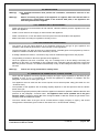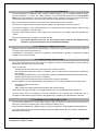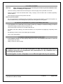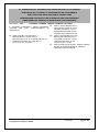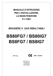
1
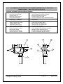
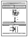
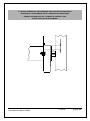
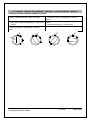
INSTRUCTION MANUAL FOR INSTALLATION, MAINTENANCE AND USE GAS KETTLES Serie 900 295.9081 295.9001 Cat. II2H3+ - 0085 01.08.00 – GB- Installations-Wartungs und gebrauchs handbuch Gasbeheizte Kochkessel S.900 01.08.00 pagina 32 INDEX Part 1: General reminders and notes 1.1. 1.2. 1.3. 1.4. 1.5. General reminders Technical data Construction Laws, technical prescriptions and directives Special requirements for the installation site 34 35 37 38 38 Part 2: Positioning, installation and maintenance 2.1. 2.2. 2.2.1. 2.2.2. 2.3. 2.3.1. 2.3.2. 2.4. 2.5. 2.5.1. 2.5.2. 2.5.3. 2.6. 2.6.1. Positioning Installation Connection to waterworks Gas connection procedures Checking the operation of the gas system Control of the gas inlet pressure Control of primary air flow Commissioning and testing Conversion to other types of gas Replacement of injectors for main burners Replacement of injectors for pilot burner Minimum output adjustment Maintenance of the appliance Possible failures and their elimination 38 39 39 39 39 40 40 40 40 41 41 41 41 42 Part 3: Use and cleaning 3.1. 3.2. 3.2.1. 3.2.4. 3.3. 3.3.1. 3.4. 3.5. 3.6. Warnings and hints for user Instructions for use Filling the jacket Switch on, start of cooking and switch off Cleaning and care of the appliance Daily cleaning Special procedures in case of long inactivity Special procedures in case of failures How to proceed, if … Installations-Wartungs und gebrauchs handbuch Gasbeheizte Kochkessel S.900 42 43 43 43 44 44 44 44 45 01.08.00 pagina 33 Part 4: Figures and details 4.1. 4.2. 4.3. 4.4. 4.5. 4.6. 4.7. Size of appliance and position of connections Measuring the inlet pressure Gas cock Pilot burner Main burner Primary air regulation Controls Installations-Wartungs und gebrauchs handbuch Gasbeheizte Kochkessel S.900 75 76 77 78 78 79 80 01.08.00 pagina 34 1.1. GENERAL REMINDERS Read the warnings contained in this manual carefully as they provide important information concerning safety during the installation, use and maintenance of the appliance. Keep these instructions carefully! Only personnel trained for its specific use should use the equipment. Keep the appliance under control during use. The appliance should be used only for the purpose for which it has been specifically designed; other uses are improper and hence dangerous. During operation surfaces can become hot and require special operation. Unplug the appliance in case of failures or improper operation. Apply exclusively to a service centre for repairs or maintenance. All important information about the appliance required for technical service is contained in the technical data plate (see figure “Size of appliance and position of connections”). In the event of technical assistance being required, the trouble must be described in as much detail as possible, so that a service technician will be able to understand the nature of the problem. Gloves should be worn to protect the hands during installation and maintenance operations. Warning! : Follow the fire prevention regulations very carefully. Installations-Wartungs und gebrauchs handbuch Gasbeheizte Kochkessel S.900 01.08.00 pagina 35 1.2. TECNICAL DATA Table 1 – General data 2959081 Type of heating: Vat usable volume: I Pressure in the vat: bar Indirect 100 -- 2959001 Indirect Model 135 -- Jacket pressure: bar 0,5 0,5 Table 2 – Sizes (see figure “Size of appliance and position of connections”) Specifications Description Models Unit of measurement Width (A) mm 900 Depth (B) mm 900 Height (C) mm 900 Vat diameter mm 600 Table 3 – General water data Specifications Description Models Unit of measurement Cold water connection mm 10 Hot water connection mm 10 Water pressure kPa 50 – 300 Table 4 – Minimum output setting G 20 – 20 mbar G 30 – 28-30/37 mbar 2,5 mbar 3 mbar Table 5 – Gas data Installations-Wartungs und gebrauchs handbuch Gasbeheizte Kochkessel S.900 01.08.00 pagina 36 Lower calorific value Hi Description Rated heating power kW 21 Minimum power kW 7 Gas connection R” ½” Nozzles diameter in 1/100 mm Consumption G20 – 2H m /h 3 2,22 kWh/m 9,45 G30 – 3+ Kg/h 1,65 kWh/kg 12,68 Pilot G20 20 mbar 40 Maximum 3 X 205 Minimum ADJUST. Pilot G30 Primary air distance 28-30/37 mbar 3 20 Maximum 3 X 135 Minimum ADJUST. G20 mm G30 30 Table 6 – Gas inlet pressure Table 6a Nominal main pressure for the different types of gas Gas family 2 – Natural Table 6b Operation permissible if pressure is in the range: Gas family 2 – Natural Table 6c Operation non permissible if pressure is lower than: Gas family 2 – Natural Table 6d Operation non permissible if pressure is higher than: Gas family 2 – Natural Gas family 3 –LPG Gas family 3 –LPG 28-30/36 mbar da 16 a 25 mbar da 20/25 a 35/45 mbar 16 mbar Gas family 3 –LPG 20/25 mbar 25 mbar Gas family 3 –LPG Installations-Wartungs und gebrauchs handbuch Gasbeheizte Kochkessel S.900 20 mbar 35/45mbar 01.08.00 pagina 37 1.3. CONSTRUCTION Main structure in steel with 4 adjustable height feet. Panels in stainless steel AISI 304, thickness 10-12/10. Cooking vat in stainless steel AISI 316, thickness 20/10. Lid in stainless steel, hinged and spring balanced in all opening positions. Chrome-plated brass drainage tap. Vat heating controlled by means of high efficiency stainless steel tubular burners resistant to mechanical and thermal stress. The gas supplied to the burner is adjusted by a cock. The appliance has a pilot burner with fixed injector, besides piezoelectric ignition. The safety of the appliance is ensured by a thermocouple that cuts off the gas flow if the pilot burner should turn off for any reason. The cold water connection is 10 mm. The hot water connection is 10 mm. The appliance is equipped with a mixer tap. 1.3.1. SPECIAL FEATURES ONLY FOR INDIRECT KETTLES Stainless steel cooking vat and chamber. To ensure safe operation, the appliance is equipped with the following devices: Steam safety valve set at 0.5 bar; Pressure gauge for steam pressure reading; Jacket steam trap; Steam pressure switch set at 0.5 bar; Jacket water supply with level control by means of taps. Safety thermostat to interrupt operation automatically in case of failures. Installations-Wartungs und gebrauchs handbuch Gasbeheizte Kochkessel S.900 01.08.00 pagina 38 1.4. LAWS, TECHNICAL PRESCRIPTIONS AND DIRECTIVES When installing the appliance it is necessary to follow and comply with the following regulations: current regulations on the matter; any hygienic-sanitary regulations concerning cooking environments; municipal and/or territorial building regulations and fire prevention prescriptions; current accident prevention guidelines; standards for the use of combustible gas; standards for gas-fired systems utilizing on-tap or liquid petroleum gas; standards relating to gas-fired cooking appliances and similar equipment used large-scale catering. Safety requirements; standards relating to gas systems for appliances used in professional kitchens and communal facilities; the regulations of the gas supply company or agency; electricity board regulations concerning safety; the regulations of the electrical power supply company or agency; any other local prescriptions. 1.5. SPECIAL REQUIREMENTS FOR THE INSTALLATION SITE The appliance belongs to the installation class A1 (no direct connection of a chimney of flue exhaust system is required), so it is very important for the environment in which it is installed to be well-aired and provided with all the safety openings prescribed for its power. In addition, it is good policy to locate the appliance under an extractor hood so that cooking vapours can be removed rapidly and continuously. The gas supply system must be equipped with a rapid on off tap approved for the purpose. This appliance requires two water connections: one for hot and one for cold water. Each line must be fitted with an on-off valve. Warning! : The shutoff valves must both be located near to the appliance, within easy reach for the user. 2.1. POSTIONING Remove all the packaging and check that the appliance is in perfect conditions. In case of visible damage, do not connect the appliance and notify the sales point immediately. Remove the PVC protection from the panels. Dispose of packaging according to regulations. Generally material is divided according to composition and should be delivered to the waste disposal service. Maintain a distance of 5 cm between the back (chimney) of the appliance and the wall. There are no particular prescriptions regarding side distances from other appliances or walls, however it is advisable to leave enough space in case of maintenance and/or repairs. It is advisable to fit a suitable heat insulation if the appliance is in direct contact with inflammable walls. The appliance must stand level. Small differences in level can be eliminated by screwing or unscrewing the adjustable feet: A significantly uneven or sloping stance can affect the operation of the appliance adversely. Installations-Wartungs und gebrauchs handbuch Gasbeheizte Kochkessel S.900 01.08.00 pagina 39 2.2. INSTALLATION Warning! : Only qualified technicians must perform the installation, maintenance and test of the appliance. Warning! : Before connecting any parts of the appliance to supplies, make sure that the latter is equivalent the requirements stated in the technical data plate, if the appliance has been designed for these supplies. 2.2.1. CONNECTION TO WATERWORKS Water inlet pressure must be between 50 and 300 kPa, otherwise install a pressure regulator on the line before the appliance. Install a cut-off valve for each supply on the line before the appliance. Water connections to 10 mm are fitted in the lower part on the left-hand side of the appliance. Make connections according to regulations currently in force. 2.2.2. GAS CONNECTION PROCEDURES The choice of the gas piping depends on the diameter required for the type of gas, appliance and installation and should be performed in conformity with current regulations. The gas feed plant can either be fixed or be disconnected; if flexible pipes are employed they must be made from stainless material and not be affected by corrosion. If sealing materials are used for connections, they must be certified and approved for the purpose. The gas fitting is located on the lower right side of the appliance Once the appliance has been connected, carry out a leakage test on all the fittings connecting the appliance to the plant. It is advisable to use a leakage spray, otherwise treat the parts with a foam that does not produce corrosion; no bubbles should develop. Carry out the leakage test also on the rapid cutoff valve. Warning! : Flames are strictly prohibited for leakage tests! 2.3. CHECKING THE OPERATION OF THE GAS SYSTEM Check that the appliance has been prepared (category and type of gas) equivalent to the family of gas available on site. If not, it is necessary to convert the appliance to whatever is available. See the paragraph “Conversion to other types of gas”. The appliance must be used with the correct injectors for its thermal power rating (See table 5 in the “Technical data”). The operation of the appliance with its heating capacity depends on the inlet pressure and the calorific power of the gas. The pressure range (inlet pressure) within which the appliance is allowed to operated is stated in table 6b “Inlet pressure” of the paragraph “Technical Data”. The appliance shall not be operated out of the given pressure range. If pressure should differ from the figures stated in table 6b, advise the gas board or the company which has installed the system. The lower calorific value of the gas can be checked with the supply company or agency, and should comply with the information given in table 5 “Gas data” in the “Technical data” heading. Installations-Wartungs und gebrauchs handbuch Gasbeheizte Kochkessel S.900 01.08.00 pagina 40 2.3.1. CONTROL OF THE GAS INLET PRESSURE The feed pressure is measured using a liquid pressure gauge ( e.g. a U-shaped pressure gauge, minimum definition 0.1 mbar). The supply pressure can be measured directly at the inlet pressure intake on the gas feed pipe. The inlet pressure intake can be reached by opening the lower front panel once the two side screws have been removed. (See figure “Measuring the inlet pressure ”). Before connecting the manometer, the screw of the pressure port must be loosened. Connect the U-shaped pressure gauge while the appliance is operating to measure pressure. The pressure reading on the gauge should be in the admitted pressure range stated in table 6b “Inlet pressures” of paragraph “Technical data”. If pressure figures should not be correct, apply to the gas board or the company which has installed the system. Having read the pressure, re-tighten the screw carefully. Warning! The sealed adjuster screws on the gas solenoid valve must not be tampered with, otherwise any guarantee rights shall be forfeited immediately. 2.3.2. CONTROL OF PRIMARY AIR FLOW Primary air can be considered correctly adjusted if no flame lift is ensured when the burner is cold and the injector lights when the burner is hot. The distance “H” (see figure “Primary air regulation”) recommended for primary air adjustment is stated in table 5 in the “Technical data”. 2.4. COMMISSIONING AND TESTING Once all the connections have been made, the appliance and the overall installation must be checked following the directions given in this manual. Check in particular: that the protective film has been removed from the external surfaces; that connections have been made in accordance with the requirements and directions indicated in this manual; that all safety requirements in current standards, statutory regulations and directives have been met; that the water and gas connections are leak-free; that the electrical connection has been performed according to standards. Now the appliance can be ignited following the instructions for use and controlling the following points: - progressive ignition of the burner; - even flames; - flame security: check these points at both minimum and maximum output. Check that the flue gas exhaust is not clogged and that they are expelled without any hindrance. The test report must be completed in full and submitted to the customer who should then sign in acceptance. With effect from this moment, the appliance is covered by the manufacturer’s warranty. 2.5. CONVERSION TO OTHER TYPES OF GAS To convert the appliance for use with another type of gas, the injectors on the main burners and on the pilot burner need to be replaced. (See table 5 and figure “Main burner”). - All the injectors needed for the different types of gas are contained in a bag supplied with the appliance. - The supply pressure and the manual setting of minimum output should also be checked. (See table 4 – Minimum output setting). Installations-Wartungs und gebrauchs handbuch Gasbeheizte Kochkessel S.900 01.08.00 pagina 41 2.5.1. REPLACEMENT OF INJECTORS FOR MAIN BURNERS – The injectors can be reached by removing the lower front panel, once the two side screws have been unloosed. – Disconnect the tube with the injectors, unloose the screws and remove. – Use a fixed wrench SW11 to unscrew the injector and replace it with a suitable one. – Re-install the primary air regulation bracket at the distance “H” as shown in table 5, see also “Primary air regulation”. 2.5.2. REPLACEMENT OF INJECTORS FOR PILOT BURNER – The injector of the pilot burner can be reached by removing the lower front panel. Remove the side and lower screws. – The pilot burner is in the front of the combustion chamber. – Unloose the screw and replace the injector with an appropriate one. 2.5.3. MINIMUM OUTPUT ADJUSTMENT – Once the appliance has been switched on, set the cock knob on the minimum position. Remove the cock knob that will reveal a small hole on the panel of the appliance. Turn the minimum adjustment screw on the cock with a screwdriver through the hole on the panel. Warning! Measure the minimum output pressure directly at the output pressure connection on the injector tube (see figure “Measuring gas pressure”) Set the output pressure of the gas cock according to the figures stated in table 4 - Minimum output setting). After setting, seal the adjustment screw! Warning! After each conversion, it is necessary to check tightness and operation! 2.6. MAINTENANCE OF THE APPLIANCE Warning! : All maintenance operations shall only be performed by a technically qualified service centre! To ensure correct and safe operation, the appliance must be inspected and serviced at least once a year only. Maintenance includes also to control the components and tear of pipes, feeding pipes etc.. It is advisable to replace worn components during maintenance operations to avoid the need for other maintenance calls and unexpected failures. It is also advisable to apply for a maintenance contract with the customer. Installations-Wartungs und gebrauchs handbuch Gasbeheizte Kochkessel S.900 01.08.00 pagina 42 2.6.1. POSSIBLE FAILURES AND THEIR ELIMINATION Warning! : Only technically qualified service centres can perform the operations described below! Warning! : Before resetting the safety thermostat, it is always necessary to eliminate the problem causing its activation (only for models with indirect heating)! Problem and possible cause Access to components and operation The content of the vat does not heat up: Safety thermostat The safety thermostat can be reached by removing the lower front panel once the two side screws have been unloosed. the safety thermostat has been activated. The pilot burner is on but the main burners do not light up: loss of pressure in gas supply; clogged injectors on main burners. The pilot burner does not light up: clogged injectors on pilot burner; faulty ignition plug; check the cable of the ignition plug. Main burners Remove the lower front panel. Pilot burner Remove the lower front panel. The pilot burner is in the front of the combustion chamber. Ignition plug and thermocouple Remove the lower front panel. The pilot burner does not remain lighted: faulty thermocouple; partially clogged injector on pilot burner; faulty cock magnet. 3.1. WARNINGS AND HINTS FOR USER This manual contains all the instructions required for a proper and safe use of our appliances. Keep the manual in a safe place for future consultation! This appliance is for catering use, hence they must be used only by trained kitchen staff. The appliance must always be kept under control during use. Warning! : The manufacturer shall not be held responsible for injuries or damage due to the noncompliance with safety rules or an improper use of the appliance by the operator. Some improper operating conditions may even be caused by an improper use of the appliance, therefore it is important to train personnel properly. All the installation and maintenance operations must be performed by fitters who are members of an official register. Respect the periods required for maintenance. With this is mind, customers are recommended to sign a service agreement. In case of failures concerning the appliance, all outputs (gas and water) must be cut off instantly. In case of recurrent failures contact a service technician. Installations-Wartungs und gebrauchs handbuch Gasbeheizte Kochkessel S.900 01.08.00 pagina 43 3.2. INSTRUCTIONS FOR USE Before cooking with the appliance for the first time wash the interior of the cooking vat thoroughly. Warning! : Fill the cooking vat up to a maximum of 40 mm under the overflow border, according to the maximum level mark, including the food to be cooked. 3.2.1. FILLING THE JACKET Warning! : The water level in the jacket must be checked each time before lighting. Warning! : It is advisable to use softened water to fill the jacket! Unscrew the filling cap on the safety valve unit. The latter is on the right of the appliance surface (see figure “Size of appliance and position of connections ”). Fill with softened water (the capacity of the jacket is stated in the paragraph “Technical data”). Check the water level by looking through the hole on the left of the front panel of the appliance. Screw back on the cap of the safety device. 3.2.2. SWITCH ON, START OF COOKING AND SWITCH OFF The appliance is equipped with a selector to start all cooking operations (see figure “Cotrols”). Here is a list of the procedures for a safe and correct use of the appliance. Lighting the pilot burner: Open the gas cock before the appliance. Turn the knob from position “” leftwards to the position “”, press the knob and together press the piezoelectric ignition button repeatedly.. Once the pilot flame is on, keep the knob pressed for a few seconds until the thermocouple heats up. Starting cooking – igniting main burner: Turn the knob leftwards to the position “ Generally cooking is started by setting the knob on the maximum heating position and once the vat has reached cooking temperature, the knob is turned to the minimum position to maintain the cooking temperature. “or until minimum position “ ” to light the burner. End of cooking – turning off main burner and pilot burner: Turn the knob rightwards until position “” to turn off the main burner; only the pilot flame will be lighted. Turn the knob again until position “” to turn off the pilot burner. (See also figure “Controls”). 3.3. CLEANING AND CARE OF THE APPLIANCE Do not use aggressive substances or abrasive detergents when cleaning the stainless steel components. Avoid using metal pads of the steel parts as they may cause rust. For the same reason avoid contact with materials containing iron. Do not use sandpaper or abrasive paper for cleaning; in special cases use a powder pumice stone. In case of particularly resistant dirt, it is advisable to use abrasive sponges (e.g. Scotch-Brite). It is advisable to clean the appliance only once it has cooled down. Installations-Wartungs und gebrauchs handbuch Gasbeheizte Kochkessel S.900 01.08.00 pagina 44 3.3.1. DAILY CLEANING Warning! : When cleaning the appliance never use direct jets of water to prevent infiltration of the liquid and damage to components. Clean the cooking vat with water and a detergent, rinse thoroughly and dry well with a soft cloth. External surfaces should be washed down using a sponge, and hot water with a suitable proprietary cleaner addend. Rinse always thoroughly and dry with a soft cloth. Note for pressure kettles: Do not use detergents containing high percentages of ammonia and sodium to clean the lid gasket, as these substances may cause damage and quickly affect the tightness of the gasket. 3.4. SPECIAL PROCEDURES IN CASE OF PROLONGED INACTIVITY If the appliance is to stand idle for any length of time (e.g. holidays or seasonal closing) it must be cleaned thoroughly, leaving not traces of food or dirt. Leave the lid open so that air can circulate inside the vat. For added care after cleaning, the external surfaces can be protected by applying a proprietary metal polish. Be absolutely certain to shut off all utilities (gas and water). Air the room appropriately. 3.5. SPECIAL PROCEDURES IN CASE OF FAILURES If the appliance should not work properly during use, turn it off immediately and close or cut off all supplies (gas and water). Apply to a service centre for help. The manufacturer shall not be held responsible nor has any warranty commitments for damage caused by non-compliance with prescriptions or by installation not in conformity with instructions. The same applies in case of improper use or different application by the operator. Installations-Wartungs und gebrauchs handbuch Gasbeheizte Kochkessel S.900 01.08.00 pagina 45 3.6. HOW TO PROCEED, IF … Warning! : Problems and failures may occur even when the appliance is used properly. Here is a list of the mist probably situations and controls that the operator should perform to avoid applying to a service centre unnecessarily. If the problem is not solved after the necessary controls, turn off the appliance immediately, cut off any supplies and apply to a service centre. … the vat contents do not heat up: check that there is gas in the mains and that the cock is open; check that the main burners are on. Otherwise turn off the unit and apply to a service centre, as the safety thermostat may have been activated because of an excess of temperature in the cooking vat. This occurs aspecially wehn the appliance is started and the vat and/or jacket is/are empty or when the appliance needs servicing because the burners are dirty and clogged. Installations-Wartungs und gebrauchs handbuch Gasbeheizte Kochkessel S.900 01.08.00 pagina 46 4.1. DIMENSIONI DELL’APPARECCHIO E POSIZIONE DEGLI ALLACCIAMENTI DIMENSIONS DE L’APPAREIL ET POSITIONS DES RACCORDEMENTS SIZE OF APPLIANCE AND POSITION OF CONNECTIONS ABMESSUNGEN DER GERÄTE UND ANORDNUNG DER VERSORGUNGEN DIMENSIONES DEL APARATO Y UBICACIÓN DE LAS CONEXIONES Mod. 9PNG…/PM8… . - LEGENDA- LEGENDE- LEGEND- LEGENDE -LEYENDA T -Targhetta caratteristiche- Plaque signalétique- A - Attacco acqua calda da 10 mm Raccord eau chaude de 10 mm Technical data plate- Typenschild-Placa de Hot water connection 10 mm caraterísticas Warmwasseranschluß 10 mm Empalme agua caliente 10 mm G - Attacco gas R½” secondo ISO 7-1 B - Attacco acqua fredda da 10 mm Raccord gaz R½” normes ISO 7-1 Raccord eau froide de 10 mm Gas connection R ½” in conformity with ISO 7-1 Cold water connection 10 mm Gasamschlußstutzen R½” nach ISO 7-1 Kaltwasseranschluß 10 mm Conexión gas R½” según ISO 7-1 Empalme agua fría 10 mm S - Scarico invaso piano pentola - Vidange capacité du plan de la marmite Overflow –Überlauf Descarga encimera marmita Installations-Wartungs und gebrauchs handbuch Gasbeheizte Kochkessel S.900 01.08.00 pagina 61 4.2. MISURAZIONE DELLA PRESSIONE DEL GAS IN ENTRATA MESURAGE DE LA PRESSION DU GAZ EN ENTREE MEASURING THE INLET PRESSURE ANSCHLUßDRUCKMESSUNG MEDICIÓN DE LA PRESIÓN DEL GAS EN LA ENTRADA LEGENDA- LEGENDE-LEGEND-LEGENDE-LEYENDA: A Presa di pressione in entrata Prise de pression en entrée Inlet pressure intake Anschlußdruckmeßstutzen Tubo de presión en entrada Installations-Wartungs und gebrauchs handbuch Gasbeheizte Kochkessel S.900 B Presa di pressione in uscita Prise de pression en sortie Outlet pressure intake Druckmeßstutzen Ausgang Tubo de presión en salida 01.08.00 pagina 62 4.3. RUBINETTO VALVOLATO DEL GAS - ROBINET SOUPAPE DU GAZ – GAS COCK GASSRELLGERÄT - GRIFO DEL GAS CON VÁLVULA LEGENDA- LEGENDE-LEGEND-LEGENDE-LEYENDA: A B C D Dado per termocoppia Ecrou pour thermocouple Thermocouple nut Mutter des Thermoelemts Turca para termocople Uscita gas - Sortie du gaz - Gas output Gasausgang – Salida gas Presa di pressione in uscita Prise de pression en sortie Outlet pressure intake Meßstutzen Gasausgang Tubo de presìon en salida Presa di pressione in entrata Prise de pression en entrée Inlet pressure intake Anschlußdruckmeßstutzen Tubo de presìon en entrada Installations-Wartungs und gebrauchs handbuch Gasbeheizte Kochkessel S.900 E F G H Vite di regolazione per la portata nominale Vis de réglage pour portée nominale Rated output adjustment screw Einstellschraube der NWB Tornillo de regulaciòn de la capacidad nominal Entrata gas - Entrée gaz – Gas inlet – Gaseingang – Entrada gas Attacco gas per bruciatore pilota Prise gaz pour brûleur pilote Gas connection for pilot burner Gasanschluß des Zündbrenners Conexiòn gas para piloto Vite di regolazione per la portata del minimo Vis de réglage pour la portée du minimum Minimum output adjustment screw Einstellschraube der Kleinstellbelastung Tornillo de regulaciòn del flujo mìnimo 01.08.00 pagina 63 4.4. BRUCIATORE PILOTA - BRÛLEUR PILOTE – PILOT BURNER – ZÜNDBRENNER – QUEMADOR PILOTO LEGENDA-LEGENDE-LEGEND-LEGENDE-LEYENDA: A B C Termocoppia – Thermocouple – Thermocouple– D Ugello – Injeteur – Injector – Düse - Boquilla Thermoelement – Termopar Bruciatore pilota – Brûleur pilote – Pilot burner - E Vite di tenuta – Vis d’étenchéité – Tightness screw Dichtschraube – Tornillo de estanqueidad Zündbrenner – Quemador piloto Candela d’accensione – Bougie d’allumage – Ignition plug – Zündkerze – Bujìa de encendido 4.5. BRUCIATORE PRINCIPALE – BRÛLEUR PRINCIPAL – MAIN BURNER – HAUPTBRENNER – QUEMADOR PRINCIPAL LEGENDA-LEGENDE-LEGEND-LEGENDE-LEYENDA: A Bruciatore–Brûleur–Burner–Brenner-Quemador C Rampa porta ugello – Rampe porte-injecteur Injector pipe–Düsenträger–Rampa porta boquilla B Ugello – Injecteur – Injector – Düse - Boquilla Installations-Wartungs und gebrauchs handbuch Gasbeheizte Kochkessel S.900 01.08.00 pagina 64 4.6. REGOLAZIONE DELL’ARIA PRIMARIA PER I BRUCIATORI PRINCIPALI REGLAGE DE L’AIR PRIMAIRE POUR LES BRÛLEURS PRINCIPAUX PRIMARY AIR REGULATION – PRIMÄRLUFTEINSTELLUNG REGULACION DEL AIRE PRIMARIO Installations-Wartungs und gebrauchs handbuch Gasbeheizte Kochkessel S.900 01.08.00 pagina 65 4.7. COMANDI – TABLEAU DE COMMANDE – CONTROLS – SCHALTELEMENTE – MANDOS LEGENDA-LEGENDE-LEGEND-LEGENDE-LEYENDA: A Manopola di comando – Poignée de commande Knob – Bedieungsknebel – Botòn de mando C Posizione di chiuso – Position de fermeture OFF positon – GeschlossenStellung – Posiciòn de cerrado D Posizione di minimo – Position de minimum – Minimum position – Kleinstellung – Posiciòn mìnimo Installations-Wartungs und gebrauchs handbuch Gasbeheizte Kochkessel S.900 E Posizione di massimo – Position de maximum Maximum position – GroßStellung – Pomiciò maximo F Posizione pilota - Position pilote – Pilot flame position Zündflammenstellung – Posiciòn piloto 01.08.00 pagina 66 CONTROLLO LIVELLO LEVEL CONTROL CONTROLE NIVEAU STEUEREINHEIT NIVEAU CONTROL NIVEL TABELLA – DATI ELETTRICI / TABLE – ELECTRICAL DATA / TABLEAU – DONNEES ELECTRIQUES / TABELLE – ELEKTRISCHE ARBEITSKRÄFTE DER DATEN / TABLA – DATI ELECTRICO Descrizione / Description / Beschreibung Unità di misura / Unit of measurement / / Descripción Unité de mesure / Maßeinh-eiten / Unidad de medida Assorbimento elettrico / Power / Abssorbement électrique / Aufnahme / Potencia W 200 Tensione / Voltage-Input / Tension / Spannung / Tensiòn AC 230 V / 60 Hz COMANDI / CONTROLS / TABLEAU DE COMMANDES / SCHALTELEMENTE / MANDOS LEGENDA / LEGEND / LEGENDE / LEYENDA 1 Pulsante accensione bruciatori / Burnwers ignition button / Bouton allumage bruleurs / Drucktaster Zündung für Brenner / Pulsador encendido quemadores 3 Lampada spia arancione riserva acqua / Finishing water orange lamp signal / Lampe témoin orange réserve d’eau / Kontrollampe orange. Wasser fehlt / Lampara espia naranja agua casi terminada 2 Lampada spia verde presenza tensione / Intension green lamp signal / Lampe témoin vert présence tension / Kontrollampe grün, Spannung vorhanden / Lampare espia verde presenzia tension 4 Lampada spia rossa mancanza acqua / Missing water red lamp signal / Lampe témoin rouge manque d’eau / Kontrollampe rot, zu wenig Wasser / Lampara espia roja falta agua Installations-Wartungs und gebrauchs handbuch Gasbeheizte Kochkessel S.900 01.08.00 pagina 67 SCHEMA ELETTRICO / WITING DIAGRAM / SCHEMA ELECTRIQUE / ELEKTRISCHER SCHALTPLAN / ESQUEMA ELECTRICO LEGENDA / LEGEND / LEGENDE / LEYENDA mA F1 SL LV LR LA TS Morsettiera arrivo linea Terminal board line arrival Bornier arrivée ligne Klemme Eingang Stromleitung Borne final de linea Fusibile 3,15 A-T Fuse 3,15 A-T Fusible 3,15 A-T Sicherung 3,15 A-T Fusible 3,15 A-T Centralina controllo livello Level control device Centrale controle niveau Steuereinheit Niveaukontrolle Centralita control nivel Led spia verde presenza tensione In-tension green lamp signal Led témoin vert présence tension Led grün, Spannung vorhanden Led espia verde presenzia tension Led spia arancio riserva acqua Finishing water orange lamp signal Led témoin orange réserve d’eau Led orange, Wasser fehlt Led espia naranja agua casi terminada Led spia rossa mancanza acqua Missing water red lamp signal Led témoin rouge manque d’eau Led rot, zu wenig Wasser Led espia roja falta agua Termostato di sicurezza Safety thermostat Thermostat de sécurité Sicherheitsthermostat Termostato de seguridad Installations-Wartungs und gebrauchs handbuch Gasbeheizte Kochkessel S.900 Tc Gi Rg Pa TR Ca S1 Termocoppia di sicurezza Safety thermocouple Termocouple de sécurité Thermoelement Sicherheitsthermostat Termocoppia de seguridad Giunto interrotto termocoppia Interrupt joint thermocouple Joint interrompu thermocouple Verbindung Unterbrechung Thermoelement Junta interupta termocoppia Rubinetto gas Gas tap Robinet gaz Gashahn Llave gas Pulsante accensione Switching on button Bouton d’allumage Drucktaster Zündung Puldor encendido Trasformatore per accensione Transformer for ignition Transformateur pour allumage Transformator für Zündung Transformador de encendido Candela di accensione Ignitor candle Bougie d’allumage Zündkerze Candela de encendido Elettrovalvola carico intercapedine (optional PAAR) Double racket charge solenoid valve (optional PAAR) Electro-soupape chargement double paroi (optional PAAR) Elektroventil Befüllung Zwischenmantel (optional PAAR) Electrovalvula carga doble pared (optional PAAR) 01.08.00 pagina 68 Installations-Wartungs und gebrauchs handbuch Gasbeheizte Kochkessel S.900 01.08.00 pagina 69