1
User Manual
EM303A General Purpose Inverter
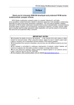
Preface
Thank you for purchasing EM303A series inverter.
Document No.: 31010005
Issue Date: 06/06/2013
EM303A is a general purpose inverter (Speed Sensorless Vector Control). It helps an
induction motor to achieve not only the speed regulation standard of a DC motor, but also
the control ability of a torque motor, and the motion control system is optimized with
quick response, precise control and system stability.
The updates of EM303A:
1. Support Modbus RTU standard communication protocol.
2. Support RS485 master-slave communication control mode, numeric synchronized
control achieved.
3. Numeric input terminals support F/R logic control, delay input control, and etc.
4. Numeric output terminals support PWL/pulse output, F/R logic output and delay output,
and etc.
5. Analog input signals VS/IS/VF/IF can be programmed as numeric inputs, numeric
terminals expansion control achieved.
6. With filtering, analog input signals VP/VS/IS/VF/IF can actively avoid analog signals
interference and drift.
7. User can easily define the display of function code menus.
8. Run, stop and parameters setting status can program the displayed parameters
independently.
It is the duty of any user to perform the appropriate, correct installation or configuration
of the optional parameters of the devices. Neither SINEE nor its distributors shall be
responsible or liable for misuse of the information contained herein or mismatching the
inverter with the motor.
In the interests of commitment to a policy of continuous development and improvement,
SINEE reserves the right to update the specification of the product or its performance, or
the content herein without notice.
More updates and information are available at www.sinee.cn.
1
User Manual
EM303A General Purpose Inverter
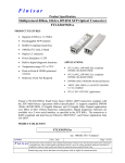
Safety Information
The addition of this symbol to a Danger or Warning safety label indicates
that an electrical hazard exists, which will result in personal injury if the
instructions are not followed.
This is the safety alert symbol. It is used to alert you to potential personal
injury. Obey all safety messages that follow this symbol to avoid possible
injury or death.
Safety Precautions
Read and understand these instructions before performing any procedure with this
inverter.
● Verifying Product upon Delivery
Caution
1. Never install an inverter that is damaged or missing components.
Failure to comply can result in injury.
z
Installation
Caution
1.
Always hold the case when carrying the inverter.
If the inverter is only held by the front cover, the main body of the inverter may fall, possibly
resulting in injury.
2.
3.
Installlation base shall be a metal plate or other non-flammable materials.
Installing the inverter on inflammable material may cause fire.
Install a cooling fan when installing more than one inverter in the same
cabinet, the temperature of the air entering the inverter shall be lower than
40℃.
Overheating may result in fire or other accidents.
2
User Manual
EM303A General Purpose Inverter
z Wiring
Danger
1. Always turn off the input power supply before wiring.
Otherwise, an electric shock or fire may occur.
2. Wiring must be performed by authorized and qualified personnel.
Otherwise, an electric shock or fire may occur.
3. Be sure the ground terminals earthed.
Otherwise, an electric shock or fire may occur.
4. Always verify the function of emergency stop terminal in work after
connecting.
Otherwise, it may result in injury. (User takes the responsibilities of wiring).
5. Never touch the input or output terminals directly with bare hands, or
connect the terminals of inverter to the housing, or connect the input
terminals to output terminals.
Otherwise, an electric shock or short circuit may occur.
Caution
1. Always confirm if the voltage of AC input power supply satisfies the rated
voltage of inverter.
Otherwise, it may result in injury and fire.
2. Never perform voltage withstanding test.
Otherwise, semi-conductors and other devices can be damaged.
3. Connect braking resistor or braking unit according to required wiring.
Otherwise, a fire may occur.
4. Tighten terminals with screw drivers of specified torque.
Otherwise, a fire may occur.
5. Never connect input power supply cable to output terminals U, V, and W.
The inverter will be damaged if voltage is applied to the output terminals.
6. Never connect phase-shifting capacitor and LC/RC noise filter to output
circuits.
Otherwise, the inverter will be damaged.
7. Never connect the solenoid switch and electromagnetic contactor to output
circuits.
When inverter is with load, surge current, which is produced by the operation of
solenoid switch or electromagnetic contactor, will trigger the overcurrent
protection circuit to act. Sometimes the inverter will be damaged.
8. Never take off the interior wires of inverter.
Otherwise, the inverter will be damaged.
3
User Manual
EM303A General Purpose Inverter
z
Trial Operation
Danger
1.
2.
3.
Only after the front cover is installed, power can be turned on. Never take
off the front cover when power is on.
An electric shock may occur.
Do not come close to the machine at power failure if fault reset function is
active. The inverter will restart automatically when power is on.
An injury may occur.
Install an emergency switch for a quick brake in case of abnormal
conditions.
An injury may occur.
Caution
1.
2.
3.
4.
z
Never touch braking resistor. It will be very hot and with high-voltage when
running.
Otherwise, an electric shock and a burn injury may occur.
Reconfirm the motor and machine are within the applicable ranges before
starting operation.
Otherwise, an injury may occur.
Do not check signals while the inverter is running.
Otherwise, the inverter will be damaged.
Be careful when editing inverter settings. The inverter is in factory default.
Otherwise, the inverter will be damaged.
Maintenance and Inspection
Danger
1.
2.
3.
4.
5.
Do not touch inverter’s wiring terminals where high voltage exists.
Otherwise, an electric shock may occur.
Always keep the front cover in place before power is supplied to the inverter.
Turn off power before taking the front cover off.
Otherwise, an electric shock may occur.
Maintenance and check must be performed only after the power supply of
main circuit is turned off, and the indicator of CHARGE is off.
An electric shock may occur due to the residual voltage on electrolytic capacitor
after power is off.
Maintenance and inspection must be performed only by authorized
professionals.
Otherwise, an electric shock may occur.
Do not change the wiring and disconnect terminal wiring when power is on.
Otherwise, an electric shock may occur and the inverter will be damaged.
4
User Manual
EM303A General Purpose Inverter
Caution
1.
CMOS ICs are installed on keypad, control circuit board and drive circuit
board respectively. Handle those parts and CMOS ICs carefully.
The CMOS IC can be destroyed by ESD if touched directly with bare hands.
2. Do not check signals while the inverter is running.
Otherwise, the inverter will be damaged.
z
Other
Danger
1.
2.
Never attempt to modify or alter the inverter.
Failure to comply can result in electric shock or injury.
User shall take full responsibilities for the damages caused by wrong wiring,
improper operation or modifying and altering, and etc.
5
User Manual
EM303A General Purpose Inverter
CONTENTS
SUPPLEMENT FOR EM303A-XXX-1C, EM303A-XXX-2C........... 8 1. OVERVIEW ................................................ 9 1.1 1.2 1.3 1.4 2 EM303A MODEL LIST AND TECHNICAL SPECIFICATIONS.......... 9 BASIC FUNCTIONS OF EM303A ............................ 11 EM303A OPERATION STATUS DEFINITION .................... 13 EM303A OUTLOOK ..................................... 17 INSTALLATION ......................................... 18 2.1 VERIFYING PRODUCT .......................................
2.2 OVERALL AND INSTALLATION DIMENSIONS ......................
2.3 CONSIDERATIONS OF INSTALLATION SITE ....................
2.4 DIRECTION AND SPACE OF INSTALLATION ....................
2.5 DISASSEMBLY AND ASSEMBLY OF KEYPAD ...................
3 WIRING ................................................ 24 3.1 3.2 3.3 3.4 3.5 4 18 19 21 21 22 CONNECTIONS TO PERIPHERALS ...........................
WIRING MAIN CIRCUIT TERMINALS .........................
WIRING CONTROL CIRCUIT TERMINALS .....................
EXTENDING KEYPAD WIRE ...............................
WIRING CHECK ........................................
24 25 32 38 38 KEYPAD OPERATION ................................... 39 4.1 TYPE AND FUNCTION OF KEYPAD .............................. 39 4.2 LED KEYPAD OPERATION MODE ........................... 40 5 TRIAL OPERATION...................................... 41 5.1 5.2 6 TRIAL OPERATION PROCEDURES ........................... 41 TRIAL OPERATION PRECAUTIONS ........................... 43 PARAMETER TABLES ................................... 45 6.1 FORMAT OF PARAMETER TABLES ...........................
6.2 PARAMETERS ..........................................
SECTION 1 GENERAL PARAMETERS ...............................
SECTION 2 ADVANCED PARAMETERS ..............................
7 45 46 46 61 PARAMETER DESCRIPTION ............................. 77 7.1 GROUP F0: GENERAL PARAMETERS ......................... 77 6
User Manual
EM303A General Purpose Inverter
7.2 7.3 7.4 7.5 7.6 7.7 GROUP F1: MOTOR PARAMETERS .......................... 88 GROUP F2: INPUT/OUTPUT TERMINAL PARAMETERS ............ 91 GROUP F3: PRESET SPEED PARAMETERS ..................... 99 GROUP F4: GENERAL PARAMETERS OF PID .................. 104 GROUP F5: GENERAL PARAMETERS OF VECTOR CONTROL ...... 112 GROUP C0: MONITORING PARAMETERS ..................... 117 8 AUTOTUNING MOTOR PARAMETERS ...................... 119 8.1 AUTOTUNING MOTOR PARAMETERS ...........................
8.2 PRECAUTIONS BEFORE AUTOTUNING.......................
8.3 AUTOTUNING PROCEDURE ...............................
8.4 AUTOMATIC TORQUE BOOST AND SLIP COMPENSATION.........
119 119 120 121 9 TROUBLESHOOTING ..................................... 123 9.1 FAULTS ................................................. 123 9.2 FAULT ANALYSIS ...................................... 125 10 MAINTENANCE AND INSPECTION ........................ 128 10.1 MAINTENANCE AND INSPECTION ............................
10.2 DAILY INSPECTION ....................................
10.3 PERIODIC MAINTENANCE................................
10.4 PERIODIC MAINTENANCE AND REPLACEMENT OF PARTS ........
10.5 OUTLINE OF WARRANTY ................................
128 128 128 129 129 11 ACCESSORIES ......................................... 130 11.1 KEYPAD EXTENSION WIRE .................................
11.2 REMOTE OPERATION CASE ..............................
11.3 BRAKING RESISTOR ......................................
11.4 BRAKING UNIT ..........................................
11.5 CONNECTING CABLE .....................................
130 130 131 132 132 12 COMMUNICATION PROTOCOL OF EM303A ................ 133 12.1 APPLICATION SCOPE ......................................
12.2 PHYSICAL INTERFACE .....................................
12.3 PROTOCOL FORMAT ......................................
12.4 DESCRIPTION OF PROTOCOL FORMAT .........................
133 133 133 136 APPENDIX 1 ............................................... 139 7
User Manual
EM303A General Purpose Inverter
Supplement for EM303A-XXX-1C,
EM303A-XXX-2C
Except input voltage, applicable motor and power wire size, EM303A-XXX-1C and
EM303A-XXX-2C are the same as EM303A-XXX-3C in terms of installation, wiring,
operation and function codes, and etc.
1. Model and Specifications of EM303A-XXX-1C and EM303A-XXX-2C Inverter
(Open Loop Vector Control)
z Rated voltage: 1-phase AC220V, 3-phase AC220V
z Applicable motor: 3-phase AC induction motor. Power ratings: 0.4~4.0 kW.
Rated voltage: AC220V
z Output voltage: 3-phase, from 0 to Usupply.
Model and rated output current of EM303A-XXX-1C are shown in Table 0-1.
Table 0-1 Model List of EM303A-XXX-1C
Rated Input
Voltage
1-Phase
AC220V
Model No.
Motor
Power(kW)
EM303A-1R1-1CB
EM303A-1R5-1CB
EM303A-2R2-1CB
EM303A-3R0-1CB
1.1
1.5
2.2
3.0
Rated Output
Current
(A)
6.2
8.0
10.0
13
EM303A-4R0-1CB
4.0
17
Overall
Dimensions
Wire Size
(m2)
The same as
EM303A-2R2G
/3R0P-3CB
2.5
4
4
6
The same as
EM303A-7R5G
/9R0P-3CB
6
See Table 0-2 for model number and rated output current of EM303A-XXX-2C.
Table 0-2 Model List of EM303A-XXX-2C
Rated Input
Voltage
3-Phase
AC220V
2.
EM303A-0R4-2CB
0.4
Rated Output
Current
(A)
3.0
EM303A-0R5-2CB
0.55
3.7
EM303A-0R7-2CB
0.75
4.8
EM303A-1R1-2CB
1.1
6.2
EM303A-1R5-2CB
1.5
8.0
EM303A-2R2-2CB
2.2
10.0
EM303A-3R0-2CB
3.0
13
EM303A-4R0-2CB
4.0
17
Model No.
Motor Power
(kW)
Overall
Dimensions
Wire Size
(m2)
1.5
1.5
The same as
EM303A-2R2G
/3R0P-3CB
L2
U
V
W
PB
Terminal block of EM303A-XXX-2C is the same as that of EM303A-XXX-1C.
8
2.5
4
4
The same as
EM303A-7R5G
/9R0P-3CB
Terminal Block of EM303A-XXX-1C and EM303A-XXX-2C
Terminal block of EM303A-XXX-1A is shown as below.
L1
1.5
6
6
User Manual
EM303A General Purpose Inverter
1. Overview
1.1 EM303A Model List and Technical Specifications
z
z
z
1.1.1
Rated voltage: 3-phase, AC380V/415V
Applicable motor: 3-phase induction motor, power range: 0.75~400kW.
Rated voltage: AC380V/415V
Output voltage: 3-phase, from 0 to Usupply.
EM303A Model and Rated Output Current
Table 1-1 Model List of EM303A
Rated Voltage
Model No.
Motor Power(kW)
3-phase,
AC380V±20
%/415V±20%
EM303A-0R7G/1R1P-3CB
EM303A-1R1G/1R5P-3CB
EM303A-1R5G/2R2P-3CB
EM303A-2R2G/3R0P-3CB
EM303A-3R0G/4R0P-3CB
EM303A-4R0G/5R5P-3CB
EM303A-5R5G/7R5P-3CB
EM303A-7R5G/9R0P-3CB
EM303A-9R0G/011P-3CB
EM303A-011G/015P-3CB
EM303A-015G/018P-3CB
EM303A-018G/022P-3C
EM303A-022G/030P-3C
EM303A-030G/037P-3C
EM303A-037G/045P-3C
EM303A-045G/055P-3C
EM303A-055G/075P-3C
EM303A-075G/090P-3C
EM303A-090G/110P-3C
EM303A-110G/132P-3C
EM303A-132G/160P-3C
EM303A-160G/185P-3C
EM303A-185G/200P-3C
EM303A-200G/220P-3C
EM303A-220G/250P-3C
EM303A-250G/280P-3C
EM303A-280G/315P-3C
EM303A-315G/355P-3C
EM303A-355G/400P-3C
EM303A-400G/450P-3C
0.75
1.1
1.5
2.2
3.0
4.0
5.5
7.5
9.0
11
15
18.5
22
30
37
45
55
75
90
110
132
160
185
200
220
250
280
315
355
400
Rated Output
Current(A)
2.8
3.7
4.8
6.2
8
10
13
17
20
26
34
41
48
60
75
90
115
150
180
220
265
310
360
380
420
470
530
600
660
740
Remarks:
1. EM303A is an integrated model with G (Fixed torque) and P (square torque) in one.
The data listed above is of Model G. When applied to square torque like blower, water
pump and etc., the power ratings of applicable motor can be one grade higher. See the
details of inverter’s nameplate.
2. See 2.1 for the model numbering scheme.
9
User Manual
EM303A General Purpose Inverter
1.1.2 EM303A Technical Specifications
Table 1-2 EM303A Technical specifications
Items
Specifications
Input
Output
Rated Voltage
3-phase AC380V~415V±20%, 50~60Hz±5%, voltage imbalance rate <3%
Output Voltage
3-phase, from 0 to Usupply.
Rated Output Current
100% rated current non-stop output
Max. Overload Current
Model G: 150% rated current for 1 minutes, 180% rated current for 2 seconds
Model P: 120% rated current for 1 minutes, 150% rated current for 2 seconds
Control Mode
V/F, SVC
Input Mode
Frequency (Speed) input, torque input
Running Mode
Keypad, control terminals (2-wire sequence, 3-wire sequence), RS485
Basic Control Functions
Frequency Control Range 0.00~600.00Hz
Input Frequency
Resolution
Numeric input:0.01Hz, analog input: 0.1% of maximum frequency
Governor Deflection
1:50(V/F), 1:100(SVC)
Speed Control Accuracy ±0.5% rated synchronous speed
Acceleration/Deceleration
0.01~600.00 seconds/minutes
Time
V/F Features
Rated output voltage: 20%~100% adjustable, frequency base :20Hz~600Hz adjustable
Torque Boost
Automatic torque boost, fixed torque boost curve, customer defined V/F curve scaling
Start Torque
150%/1Hz(V/F),150%/0.5Hz(SVC)
Torque Control Accuracy ±15% rated torque (SVC1)
AVR
AVR is active while output voltage remains unchanged if input voltage is varying.
Automatic Current Limit Automatically limit output current, avoid frequent overcurrent tripping
Special
Function
Function of Input and
Output
Control
DC Brake
Brake frequency:0.1~60Hz, brake time:0~30S, brake current:0~100% rated current
Signal Input Source
Communication, analog voltage, analog current, preset speed, simple PLC and their
combinations
Textile Wobbulation
Realize textile wobbulation functions like wobbulation range, time and jump
Droop Control
With increase of load, the speed droops, suitable for one machine driven by multi-motor
Reference Power
10V/20mA
Terminal Control Power
24V/150mA
Numeric Input Terminals 7 programmable numeric input terminals
Analog Input Terminals
4 analog inputs:2 voltage inputs (0~10V), and 2 current inputs(0~20mA)
2 OC outputs and 1 relay output are programmable. Maximum output current of OC:
Numeric Output Terminals50mA. Relay contact capacity: 250VAC/3A or 30VDC/1A. When relay acts, EA-EC is
NO, and EB-EC is NC.
Analog output Terminals 2 programmable analog output terminals can output 0~10V or 0~20mA
Keypad
LED
Human interactions with displays and control actuators
Display
Parameter Copy
Upload and download parameter information of the inverter, copy parameters rapidly.
Protections Protections
Applica-tion
Conditions
Short circuit, overcurrent, overload, overvoltage, undervoltage, phase loss, overheating,
external fault, and etc.
Installation Site
Indoor, with altitude less than1,000 meters, free from dust,corrosive gas, and direct
sunlight
Ambient Temperature
-10℃~+40℃. In the temperature range +40 °C…+50 °C, the rated output current is
decreased by 1% for every additional 1 °C. 20%~90%RH (no condensation)
Vibration
<0.5g
Storage Temperature
-25℃~+65℃
Installation Method
Wall mounting, or floor mounting
Degree of Protection
IP20
Cooling Method
Forced air cooling
10
User Manual
EM303A General Purpose Inverter
1.2
Basic Functions of EM303A
1.2.1 Process PID Control
2 process PID control modes: Speed process PID control and torque process PID
control. When output of process PID control is taken as inverter’s speed input, it
is speed process PID control. When output of process PID control is taken as
inverter’s torque input, it is torque process PID control. Speed process PID
control is applicable to all drive modes, while torque process PID control is only
active in SVC1.
Speed process PID control is used for:
z Pressure control: Regulate motor speed by taking pressure signal as a feedback
to keep pressure constant.
z Flow control: Regulate motor speed by taking flow signal as a feedback to keep
flow constant.
z Temperature control: Regular motor speed by taking temperature signal as a
feedback, to keep temperature constant.
Torque process PID control is used for:
z Tension control: Regulate motor’s torque current by taking tension signal as a
feedback to keep tension constant.
1.2.2 Program Operation (Simple PLC)
Program operation is that inverter finishes specified control logic according to the
mode and time set in the program. Program operation is categorized as speed
program operation, torque program operation and process PID program operation
(including speed and torque process PID program operation). The program
operation mode can be further categorized as: Single-cycle (stop after
completion), run at the 7th preset speed after single-cycle, limited continuous
cycle (stop after completion), and unlimited continuous cycle.
1.2.3 Wobbulation Operation (Textile only)
Wobbulation is applied to textile and chemical fiber industry that needs for
traverse and winding.
1.2.4 Stepping Mode Operation
Provide 5 stepping input modes for speed, torque and process PID input control
modes.
1.2.5 Droop Control
When the machine is driven by multi-motor, setting function of droop control can
evenly assign the output power of each inverter.
1.2.6 Stop Control at Power-off
When driving load with big inertia, the inverter will automatically enter stop
control status in case of power failure, and convert the rotational kinetic energy
into electrical energy to stop the motor quickly. It prevents the system from free
revolving with big inertia for a long time.
11
User Manual
EM303A General Purpose Inverter
1.2.7 Low Noise Design
Due to the high frequency harmonic wave with the output of inverter, the motor
generates the electromagnetic noise inevitably. Usually, electromagnetic noise can
be lowered by increasing carrier frequency, which, however, in turn makes the
inverter overheat, and the rated output current is required to be decreased by 5%
for every additional 1 kHz in carrier frequency. EM303A achieves low noise
operation with low carrier frequency by carrier frequency regulation.
1.2.8 Current Limit
When inverter is running, if acceleration/deceleration time is too short or the load
becomes heavier, the output current of inverter may exceed the permitted limit. If
current limit is enabled, inverter will automatically decrease its output frequency
to keep the output current limit unchanged. When output current is less than the
current limit, it runs as per regular input command. This function is applied to
V/F control mode only. For other control modes, the current is automatically
regulated.
1.2.9 Energy Autosaving
When motor is idling or with light load, EM303A will properly regulate its output
voltage for energy saving purpose.
1.2.10 Constant Power Output
With the same load, output current will increase as the input voltage of inverter
decreases. Meanwhile, if constant power output is active, the inverter will
automatically calculate its real-time output power and work at maximum power
permitted.
1.2.11 Automatic Voltage Regulation (AVR)
When the input voltage fluctuates, the output voltage remains unchanged
basically, and V/F value keeps constant.
1.2.12 Dynamic Overvoltage Stall
Effectively avoid bus voltage accumulation by real-time detecting voltage of DC
bus and regulate overvoltage points dynamically.
1.2.13 Dynamic Brake
When motor decelerates or runs with potential energy load, the voltage of DC bus
will rise due to energy feedback, and such voltage is called as rebounding
overvoltage. In order to make motor brake quickly within given deceleration time
while the inverter will not perform overvoltage protection, and rebounding
braking resistor or braking unit can be used to consume this energy, such brake is
called as dynamic brake.
1.2.14 Fault Autoretry
During operation of inverter, faults such as undervoltage (instant power failure
but resume immediately), overvoltage, overcurrent, and overload may occur. If
faults autoretry is active, inverter will automatically try to restart after a setting
12
User Manual
EM303A General Purpose Inverter
interval. Meanwhile, if speed search is active, inverter will automatically detect
motor speed and direction to make it return the setting input frequency smoothly.
1.2.15 Multi-function Numeric Input Terminals
7 multi-function numeric input terminals X1 ~ X7 of EM303A can be
programmed based on real needs.
1.2.16 Multi-function Analog Output Terminals
Multi-function analog output terminals M0~M1 of EM303A can be defined as
different information, or as signals of 0~10V or 0~20mA.
1.2.17 Multi-function Numeric Output Terminals
The output of multi-function numeric output terminals Y1 and Y2, and relays of
EM303A can be programmed based on real needs.
1.2.18 Autotuning Motor Parameter
When autotuning motor parameters is enabled, the inverter will autotune and save
the motor parameters. (Autotuning motor parameter is categorized as stationary
autotuning and rotational autotuning. Please make motor in idling status by
separating motor and load if taking rotational autotuning mode. )
1.2.19 Parameter Copy
All function parameters of EM303A can be copied through keypad.
1.2.20 Programmable Displayed Information
Monitoring codes C0-00 ~ C0-31 of EM303A can be displayed by setting
program.
1.2.21 RS-485 Interface
Through RS-485 interface and computer monitoring software, multi-inverter
operation can be easily achieved with computer network.
1.2.22 User Password
User can set password to protect function codes from unauthorized editing.
1.2.23 Overmodulated Output
When the load is heavy, overmodulation can raise the output voltage of inverter
and lower motor current, and then lower motor temperature rising.
1.2.24 Oscillation Suppression
Mechanical load may have mechanical resonance point, and motor may have
electromagnetic resonance point. Oscillation suppression can eliminate resonance
and enable system to operate stably and to be free from failures.
1.3
EM303A Operation Status Definition
1.3.1 Operation Status of Inverter
z Parameters setting status: After power is on, inverter finishes initialization
enters standby status without fault or start-up command, and does not output.
z Normal running status: After receiving active start command through
keypad, control terminal or RS485, the inverter drives motor in accordance
13
User Manual
EM303A General Purpose Inverter
with the requirements of setting input.
z JOG running status: Set by keypad, external terminal or RS485 to make
motor run per JOG input speed.
z JOG stop status: Refer to the process that the output frequency drops to zero
in JOG deceleration time after JOG running command is not active.
z Autotuning status: Set by keypad to autotune motor’s parameters in
stationary or rotational autotuning.
z Stop status: Refer to the process that the output frequency drops to zero in
given deceleration time after running command is not active.
z Fault status: Status of inverter at protections, all kinds of faults and failures.
1.3.2 Control Modes of Inverter
The control modes of inverter refer to that the inverter controls motor rotation as
per required speed and torque with open loop or close-loop control mode. The
control modes include:
z General open loop space vector control——V/F control
Applicable to the applications of slow speed changes and low speed stability
accuracy demand, and meet needs of most of AC motor drives.
z SVC 0—— Open-loop vector control without PG feedback
Only estimate speed in real-time, but no feedback control. Output current is
under real-time close-loop control, output of motor reaches 150% of rated
torque at 0.5Hz, and inverter automatically traces load variables and limit
output current to make it not exceed the maximum value. Even if there is
sudden load change, quick acceleration or deceleration, inverter will not trip
overcurrent, short-circuit, and etc., and keeps high performance and reliability.
z SVC1—— Torque control(Close-loop vector control without PG feedback)
Not only estimate speed in real-time, but also conduct feedback control. Speed
and current are under real-time close-loop control. Not only speed control but
also torque control can be realized. A regular AC induction motor can be
converted to AC variable speed motor and AC torque motor by adopting this
control mode. It is a genuine speed sensorless vector control.
1.3.3 Setting Modes of Inverter
The setting mode of inverter refers to that what kind of physical quantity inverter
is taken as control object when driving motor.
z Speed setting mode is to take motor speed as the control object
z Torque setting mode is to take motor torque as the control object.
Set through various and flexible methods such as numeric setting, analog voltage,
and analog current or other mathematical combinations. Jog speed setting mode
is prior to other setting modes, i.e. when pressing JOG button on keypad or
making control terminals FJOG and RJOG on, no matter what the present setting
mode is, the inverter will automatically switch to jog speed setting. See Figure
1-1 and Figure 1-2 for the details of all speed setting modes of EM303A.
14
User Manual
EM303A General Purpose Inverter
Figure 1-1 Speed Setting Modes
15
User Manual
EM303A General Purpose Inverter
Figure 1-2 Torque Input Modes
16
User Manual
EM303A General Purpose Inverter
1.3.4 Operation Control Mode of Inverter
The operation control mode of inverter refers to the action conditions when
inverter enters operation status, which includes 3 modes as controlled by keypad
operation, terminal operation, and RS485 communication. Terminal operation
mode is categorized as 2-wire sequence, and 3-wire sequence. The setting details
and control logic of these three modes are shown in the description of function
parameters F0-04 and F0-05 in 7.1.
1.4
EM303A Outlook
See Figure 1-3 for the outlook of EM303A (Instance: EM303A- 4.0kW).
Figure1-3 EM303A Outlook
The face terminal cover can be taken away by following the arrow shown in
Figure1-3. See Figure 1-4 for control circuit terminals and main circuit terminals.
a.
R
Control Circuit Terminal Block
S
T
U
V
W
PB
b. Main Circuit Terminal Block
Figure 1-4 Control Circuit Terminals and Main Circuit Terminals
17
User Manual
EM303A General Purpose Inverter
2 Installation
2.1 Verifying Product
Refer to Table 2-1, and check and verify the EM303A.
Table 2-1 Check List
Item
Action
If the products are identical to the Check the devices reference marked on
purchase order.
the label.
Any part damaged.
Check the outlook if any damages.
Any screw loosened.
Check with a screwdriver if necessary.
Contact the distributor or SINEE directly for quality issue.
z Nameplate
z Model Numbering Scheme
18
User Manual
EM303A General Purpose Inverter
2.2 Overall and Installation Dimensions
Classified to 10 sizes for total 30 models of EM303A, installation dimensions as
shown in Figure 2-1 and Table 2-2.
The keypad can be installed on the metal panel separately with a hole size of
116.5±0.1(L)*71.5±0.1 (W)mm, and applicable panel thickness:1.2~2.0mm
71
34
26
74
8
58
2-M3
16
77
116
R
118
-
D1
D1
D2
D2
(a)Keypad Dimensions for Installation
W
W1
W
W1
4-d
D
D
-
R
R
H1
H
H2
H1
H
-
2-d
(b)
(c)
Figure 2-1 Overall and Keypad Dimensions of EM303A for Installation
19
User Manual
EM303A General Purpose Inverter
Table 2-2 Overall and Installation Dimensions of EM303A
Model No.
W
W1
H
H1
H2
D
D1
D2
d
Frame
140
125
220
205
--
152
120
161
6
(b)
165
148
250
235
--
161
126
170
6
(b)
215
150
352
335
317
215
172
224
7
(c)
270
200
470
450
424
245
187
254
10
(c)
335
240
550
530
500
245
190
254
10
(c)
390
300
695
665
635
250
200
259
12
(c)
560
400
828
803
775
355
255
364
12
(c)
650
400
1060
1034
1000
400
325
409
13
(c)
825
660
1200
1170
1137
400
320
409
13
(c)
1068
870
1213
1183
1150
410
330
419
13
(c)
EM303A-0R7G/1R1P-3CB
EM303A-1R1G/1R5P-3CB
EM303A-1R5G/2R2P-3CB
EM303A-2R2G/3R0P-3CB
EM303A-3R0G/4R0P-3CB
EM303A-4R0G/5R5P-3CB
EM303A-5R5G/7R5P-3CB
EM303A-7R5G/9R0P-3CB
EM303A-9R0G/011P-3CB
EM303A-011G/015P-3CB
EM303A-015G/018P-3CB
EM303A-018G/022P-3C
EM303A-022G/030P-3C
EM303A-030G/037P-3C
EM303A-037G/045P-3C
EM303A-045G/055P-3C
EM303A-055G/075P-3C
EM303A-075G/090P-3C
EM303A-090G/110P-3C
EM303A-110G/132P-3C
EM303A-132G/160P-3C
EM303A-160G/185P-3C
EM303A-185G/200P-3C
EM303A-200G/220P-3C
EM303A-220G/250P-3C
EM303A-250G/280P-3C
EM303A-280G/315P-3C
EM303A-315G/355P-3C
EM303A-355G/400P-3C
EM303A-400G/450P-3C
Remarks:
z 5
models:
EM303A-055~075,
EM303A-090~132,
EM303A-160~200,
EM303A-220~280, and EM303A-315~400 can be floor-mounted with a chassis
which is in the same width as the inverter. Heights of optional chassis: 120mm,
250mm, 300mm, 300mm and 350mm.
z EM303A-090 or above: power input terminals are on the top, and power output
terminals are at the bottom of the inverter.
20
User Manual
EM303A General Purpose Inverter
2.3 Considerations of Installation Site
2.3.1 Installation Site
Considerations for installation site:
z Good ventilation indoor
z Ambient temperature: -10°C~+40°C
z No high temperature and high moisture, humidity:<90%RH, no water drops or
any other condensation
z Never install on flammable materials
z No direct sunlight
z No flammable, corrosive gas or liquid
z No dust, floating fiber or metal particles
z Firm and steady installation base
z No electromagnetic interference, and keep away from interference source.
2.3.2 Ambient Temperature
Install inverter in a place with good ventilation to improve the reliability of inverter
operation. When inverter is mounted inside a cabinet, cooling fan or air conditioner
is a must. Keep the ambient temperature below +40°C.
2.3.3 Precautions
Take protective measures during installation to prevent foreign matters like metal
particles or dust from entering the inverter when drilling. After installation, please
take off the protective object.
2.4 Direction and Space of Installation
Cooling fan(s) installed inside EM303A is for forced air cooling. For good cooling
circulation, mount inverter vertically, and leave sufficient space between the
inverter and wall or other objects. See Figure 2-2.
Figure 2-2 Installation Direction and Space
21
User Manual
EM303A General Purpose Inverter
2.5 Disassembly and Assembly of Keypad
Under general circumstances, it is unnecessary to disassemble the keypad, and just
remove the cover to assemble and wire. On special occasions, disassemble the
keypad by following steps.
z
Remove the front cover: For EM303A-7R5 or below, push the cover vertically
from the bottom with two hands, and then lift up outwards. See Figure 2-3.
Figure2-3 Remove the Front Cover
z
Disassemble the keypad: Put your figures in the insert on the top of keypad,
press down slightly, and pull outwards, then the keypad can be removed. See
Figure 2-4.
z
Assemble the keypad: Place the bottom of keypad in the slot and then press the
top to push until it clicks into right place. See Figure 2-5.
22
User Manual
EM303A General Purpose Inverter
Figure 2-4 Disassemble the Keypad
Figure 2-5 Assemble the Keypad
23
User Manual
EM303A General Purpose Inverter
3 Wiring
3.1 Connections to Peripherals
Connections between EM303A and its peripherals are shown in Figure 3-1
Figure 3-1 EM303A Peripherals Connections
24
User Manual
EM303A General Purpose Inverter
3.2 Wiring Main Circuit Terminals
3.2.1 Main Circuit Terminal Block
See Figure 3-2 for main circuit terminal block.
R
S
T
U
V
W
PB
(a) Main Circuit Terminal Block of EM303A-015 or below
R
S
T
U
V
W
(b)Main Circuit Terminal Block of EM303A-018~075
POWER
R
U
S
T
V
W
MOTOR
(c) Main Circuit Terminals of EM303A-090 or above
Figure3-2 Main Circuit Terminal Block
Remarks:
1. EM303A-090 or above: Power input terminals R, S, and T are on the top, and
power output terminals are at the bottom of the inverter.
2. EM303A-315 or above: There are 2 wiring screws for each terminal.
25
User Manual
EM303A General Purpose Inverter
3.2.2 Main Circuit Terminal Functions
The main circuit terminal functions of EM303A are listed in Table 3-1. Wire the
terminals correctly as per corresponding function.
Table 3-1 Main Circuit Terminal Functions
Terminal
Function
R, S, T
U, V, W
PB
AC power input terminals for connecting to 3-phase AC power.
(Terminal L1, L2 for AC220V 1-phase input inverter)
Inverter AC output terminals for connecting to 3-phase induction motor.
Positive and negative terminals of internal DC bus for connecting to
external braking unit.
Connecting terminals of braking resistor, one end connected to and the
other to PB.
Grounding terminals
3.2.3 Standard Wiring of Main Circuit
See Figure 3-3 for standard wiring of main circuit.
EM303A-018~400
EM303A-0R7~015
Terminal L1&L2 for inverters with 1-phase AC220V
input
Figure 3-3 Standard Wiring of Main Circuit
3.2.4 Wiring Main Circuit on Input Side
Installing a Circuit Breaker
Always install an air circuit breaker (MCCB) between the power supply and input
terminals.
z Choose a MCCB with a capacity of 1.5-2 times of the inverter’s rated current.
z The time characteristics of MCCB should meet that of inverter’s overheating
protection (150% of rated current /1 minute).
26
User Manual
EM303A General Purpose Inverter
z If single MCCB is shared by two or more inverters or other devices, the contact
of fault output relay shall be connected to power contactor coil, so that the power
supply will be turned off by the fault signals, as shown in Figure 3-4.
EM303A
MCCB
R
S
MC
OFF
ON
MC
T
EB Fault Relay
EC
Contact
Figure 3-4 Connecting to Input Circuit Breaker
Installing a Leakage Circuit Breaker
High frequency leakage current is generated by high frequency PWM signal output
of inverter. Select a special purpose leakage breaker with a trigger current≥30mA.
For a regular leakage breaker, the trigger current≥200mA and the active time at
0.1S or above.
Installing an Electromagnetic Contactor
Install an electromagnetic contactor which is applicable to inverter as shown in
Figure 3-4.
z Start/stop of the inverter can be controlled by the electromagnetic contactor on
input side. Inverter may break down if the electromagnetic contactor is on and off
frequently. The operation interval between start and stop of the inverter shall ≥ 30
minutes, if electromagnetic contactor on input side must be used for controlling.
z The inverter will not automatically start if power is on after failure.
Connecting to the Terminal Block
Power input phase sequence is not related to the phase sequence of terminals R, S,
and T on the terminal block, any two of them can be connected randomly.
Installing an AC Reactor
If the inverter is connected to a transformer with big-capacity (≥600kVA), or power
supply is connected to capacitive load, an excessive big surge current will occur
and rectifier of inverter can be broken down. Install an optional 3-phase AC reactor
on input side of inverter to suppress peak current and voltage, and improve power
factor of the system.
27
User Manual
EM303A General Purpose Inverter
Installing a Surge Absorber
Install a surge absorber for inductive loads (electromagnetic contactors, solenoid
valves, solenoid coils, or electromagnetic circuit breakers) nearby the inverter.
Installing a Noise Filter on Power Supply Side
To filter noise transmitted between power cable and the inverter, and the impact on
power grid caused by the noise produced by the inverter.
z A special purpose noise filter is required for the inverter.
z Correct vs incorrect installations of noise filters as shown in Figure 3-5 and
Figure 3-6.
Figure 3-5 Correct Noise Filter Installation
(a)
(b)
Figure 3-6 Incorrect Noise Filter Installation
3.2.5 Wiring the Output Side of Main Circuit
Connecting the Inverter to Motor
Connect inverter output terminals U, V, and W to motor input terminals U, V and W.
Check that the motor forwards with the Forward Command. Switch any 2 of the
inverter output terminals U, V, or W to each other and reconnect if the motor
reverses.
28
User Manual
EM303A General Purpose Inverter
Never Connecting Power Supply Cable to Output Terminals
Never connect power supply cable to output terminals. If power is input to the
output terminals, the inverter would be damaged.
Never Short-Circuiting or Grounding Output Terminals
Never touch output terminals directly with bare hands, or connect the output cable
to the housing of inverter. Otherwise, an electric shock and short-circuit may occur.
Furthermore, do not short-circuit the output cable.
Never Using a Phase-shifting Capacitor
Never connect phase-shifting electrolytic capacitor or LC/RC filter to the output
circuit. Otherwise, inverter will be damaged.
Never Using an Electromagnetic Switch
Never connect electromagnetic switch or electromagnetic contactor to the output
circuit. Otherwise, failure to comply will cause overcurrent or overvoltage
protection. Even worse, inverter will be damaged.
Make sure that the inverter stops before installing electromagnetic contactor to
switch grid power supply.
Installing a Noise Filter on the Output Side
Install a noise filter on the output side of inverter to reduce inductive interference
and radio interference.
z Inductive interference: Electromagnetic induction generates noise on the signal
line which may cause the control device malfunction.
z Radio interference: The high frequency electromagnetic waves generated by
inverter and cable cause radio devices nearby to make noise when receiving
signals.
Figure 3-7 Installing a Noise Filter on the Output Side
Countermeasures Against Inductive Interference
As stated previously, except installing a noise filter, all output cables can be routed
through a grounded metal pipe to prevent inductive interference on the output side.
29
User Manual
EM303A General Purpose Inverter
The distance between output cables and signal line should>30cm, and the inductive
interference will be reduced considerably, as shown in Figure 3-8.
Figure 3-8 Countermeasures Against Inductive Interference
Countermeasures Against Radio Frequency Interference (RFI)
RFI will be generated from the inverter as well as the input cable and the output cable.
Install noise filters on both input and output sides, and shield inverter with an iron
case to reduce RFI. As shown in Figure 3-9.
Figure 3-9 Countermeasures Against RFI
Cable Length Between Inverter and Motor
The longer cable between the inverter and motor is, the higher carrier frequency is, and
the greater high-frequency harmonic leakage current on its cable is. All of which will
affect inverter and its peripherals. See Table 3-2 to adjust carrier frequency for reducing
the high-frequency harmonic leakage current.
When motor cable>50m, connect a special 3-phase AC reactor of the same capacity as
that of the inverter to the output terminals.
Table 3-2 Cable Length and Carrier Frequency Between Inverter and Motor
Cable Length
<50m
<100m
>100m
Carrier Frequency
<10kHz
<5kHz
<2kHz
F0-14 Function Parameter
10.000
5.000
2.000
30
User Manual
EM303A General Purpose Inverter
3.2.6 Main Circuit Cable and Terminal Screw Size
See Table 3-3 for the specifications of main circuit cable and terminal screw.
Table 3-3 Main Circuit Cable and Terminal Screw Specifications
EM303A-018G/022P-3C
M3.5
M3.5
M3.5
M3.5
M3.5
M3.5
M4
M4
M5
M5
M5
M6
Tightening
Torque
(N.m)
1.2~1.5
1.2~1.5
1.2~1.5
1.2~1.5
1.2~1.5
1.2~1.5
1.5~2.0
1.5~2.0
3.0~4.0
3.0~4.0
3.0~4.0
4.0~5.0
EM303A-022G/030P-3C
EM303A-030G/037P-3C
EM303A-037G/045P-3C
EM303A-045G/055P-3C
EM303A-055G/075P-3C
EM303A-075G/090P-3C
EM303A-090G/110P-3C
EM303A-110G/132P-3C
EM303A-132G/160P-3C
EM303A-160G/185P-3C
EM303A-185G/200P-3C
EM303A-200G/220P-3C
EM303A-220G/250P-3C
EM303A-250G/280P-3C
EM303A-280G/315P-3C
EM303A-315G/355P-3C
EM303A-355G/400P-3C
EM303A-400G/450P-3C
M6
M6
M8
M8
M10
M10
M10
M10
M10
M12
M12
M12
M16
M16
M16
2*M16
2*M16
2*M16
4.0~5.0
4.0~5.0
9.0~10.0
9.0~10.0
17.0~22.0
17.0~22.0
17.0~22.0
17.0~22.0
17.0~22.0
31.0~39.0
31.0~39.0
31.0~39.0
45.0~55.0
45.0~55.0
45.0~55.0
45.0~55.0
45.0~55.0
45.0~55.0
Model No.
of Inverter
EM303A-0R7G/1R1P-3CB
EM303A-1R1G/1R5P-3CB
EM303A-1R5G/2R2P-3CB
EM303A-2R2G/3R0P-3CB
EM303A-3R0G/4R0P-3CB
EM303A-4R0G/5R5P-3CB
EM303A-5R5G/7R5P-3CB
EM303A-7R5G/9R0P-3CB
EM303A-9R0G/011P-3CB
EM303A-011G/015P-3CB
EM303A-015G/018P-3CB
Terminal
Screw
Terminals
, ,R,S,T,U,V,W,PB,
R,S,T, , ,U,V,W,
Cable
Cable
Size
Type
(mm2)
1.5
2.5
2.5
4
4
4
6
6
6
10
10
16
16
25
25
35
35
60
60
90
90
120
180
180
240
270
270
2*150
2*150
2*180
750V
Remarks:
1. See Table 0-1 and Table 0-2 for the terminals and cable selection of AC 220V input.
2. Take the voltagedrop into consideration for selecting cable. Generally the voltagedrop
should be<5V and calculated according to following formula:
Voltagedrop=√3* Cable resistance ratio (Ω/KM)*Cable length (m)*Rated current
(A)*10-3
3. If placed in plastic duct, the cable should be uprated by one level.
4. The cable should be connected to the applicable cable and wiring terminal.
5. The size of grounding cable should be the same as that of power cable when the size of
power cable is less than 16mm2. However, when it is>16mm2, the size of grounding
cable should not be less than half of 16mm2, but at least 16mm2.
31
User Manual
M
EM303A General Purpose Inverter
I
2.7 Ground Wiring
3.2
ound terminal
groounded.
z Make sure the gro
z Do not share the grounding
g
cable with welding machine or power
p
equipment.
z The size of grou
unding cable should m
meet the technical sttandard of electrical
appliances, and thhe distance to groundiing point should be ass short as possible.
z Do not form the grounding cable as a circuit whenever tw
wo or more inverters
are used synchrronously. See Figurre 3-10 for the corrrect and incorrect
grounding wirings.
Figure 3-10 Grouund Wiring
3.2
2.8 Wiring Braking Resistor and Brakin
ng Unit
See Chapter 11 for
f more details about the selection and
d wiring of braking
resistor and brakinng unit.
3.3 Wiring
W
Control Circuit
C
Terminals
3.3
3.1 Control Circuit Terminals
T
The
T control circuit term
minals of EM303A arre located on the contrrol PCBA:
z Analog input termin
nals: Voltage input siggnals VS,VF. Current input signals IS,IF.
z Numeric input term
minals: X1, X2, X3, X44, X5, X6, X7, PLC
z Numeric output term
minals: Y1, Y2, EA, E
EB, EC
z Analog output term
minals: M0, M1
z Auxiliary power sup
pply terminals: +24V,
V, COM, +10V, GND.
z RS485 communicattion interface: A+,A
Az Grounding terminall: PE
See
S Figure 3-11 for coontrol circuit terminal block.
Figure 3--11 EM303A Control Circuit Terminal Blocck
32
User Manual
EM303A General Purpose Inverter
3.3.2 Function and Wiring of Control Circuit Terminals
Function of control circuit terminals as shown in Table 3-4
Table 3-4 Function of Control Circuit Terminals
Mode
Analog
Input
Terminal
VS
VS Analog voltage input
VF
VF Analog voltage input
IS
IS Analog current input
IF
IF Analog current input
X1/RUN
X2/ F/R
X3~ X7
Numeric
Input
Terminal Name
COM
PLC
EB
MultiOutput
Analog
Output
Auxiliary
Power
Supply
(Configured as numeric input terminal)
terminal(Ground of 24V power supply)
Common terminal for external connection
Multi-function input
with 24V
common terminal
The default is to connect with 24V supply
EA-EC:NO
Relay output terminal
EB-EC:NC
M0
Analog output terminal 0
COM
0/4~20mA
Switching value input/output signal common
OC output terminal 2
24V
(Configured as numeric input terminal)
common terminal
Y2
GND
0/4~20mA
setting function(Common Terminal: PLC)
OC output terminal 1
10V
(Configured as numeric input terminal)
Multi-function input
Y1
M1
0/2~10V
F2-00~F2-06 to achieve the input control of
terminal
EC
function
(Configured as numeric input terminal)
Program the relevant terminals by setting
Multi-function input
EA
Relay Output
Terminal Function
0/2~10V
Programmable multi-function output terminals
as shown in F2-12, F2-13.
Analog output terminal 1
Analog terminal power
supply
Analog output 0~10V or 0~20mA can be
defined by setting of F2-16, F2-17 or F2-19,
F2-20.
+10V/20mA
Common port of analog
Common port of analog input and output
quantity
signals(Ground of 10V power supply)
Auxiliary power supply
Switching value common
terminal
Output of DC24V/150mA between it and
COM
Common terminal of switching value
input/output signal (Ground of 24V power
supply)
Communica
A+
RS485 communication
485 differential signal positive terminal
-tion
A-
interface terminal
485 differential signal negative terminal
Shield
PE
Shielded grounding
For shielded terminal cable grounding
33
User Manual
EM303A General Purpose Inverter
3.3.2.1 Wiring the Analog Input Terminals
Wiring terminals VS and VF through analog voltage signal:
When analog voltage input signal is as the external power supply, wire terminals
VS and VF as per the method shown in Figure 3-12-a.
When analog voltage input signal is as the potentiometer, wire terminals VS and
VF as per the method shown in Figure 3-12-b.
(a)
(b)
Figure 3-12 Wiring of Terminals VS and VF
Wiring terminals IS and IF through analog current signal:
Figure 3-13 Wiring of Terminals IS and IF
3.3.2.2 Wiring Multi-function Input Terminal
The multi-function input terminals of EM303A adopt full bridge rectifier circuit.
Terminal PLC is the common terminal of X1~X7. The current passed through the
PLC terminal can be forward (NPN Mode) or reverse (PNP mode), so that it is
flexible to connect terminals X1-X7 to external components. The typical wirings are
as shown in the followings:
NPN and PNP wirings of multi-function numeric input terminals(X1~X7)
(See F2 Group for parameter setting)
A.
Dry contact
mode
wiring B.
NPN mode with external C.
supply
34
PNP mode with external
supply
User Manual
EM303A General Purpose Inverter
3.3.2.3 Wiring Relay Output Terminal
The surge voltage absorbing circuit should be installed for inductive load like relay
or contactor. For instance: RC absorbing circuit (please note that the leakage current
should be less than the working current of contactor or relay being controlled), VDR
or fly-wheel diode and etc. (For DC electromagnetic circuit, please pay attention to
the polarity at installation). The component of absorbing circuit should be installed
near the ends of relay coil or contactor.
3.3.2.4 Wiring Multi-function Output Terminal
Multi-function output terminals Y1 and Y2 can take 24V internal power supply of
inverter or external power supply as shown in Figure 3-14.
a: Internal power supply
b: External power supply
Figure 3-14 Wiring of Multi-function Output Terminals
3.3.2.5 Wiring Analog Output Terminals
Analog output terminals M0 and M1 can represent various physical quantities when
connected to external analog meter. The specifications of jumper are taken as:
0~20mA output current or 0~10V output voltage, here M0 and M1 correspond to
JP1 and JP2 respectively. See the wiring of jumper and terminals in the following
table.
JP1
JP2
35
M0: Analog
output
voltage
M0: Analog
output
current
M1: Analog
output
voltage
M1: Analog
output
current
User Manual
EM303A General Purpose Inverter
3.3.2.6 Wiring Communication Terminal
Terminals A+ and A- are the RS485 communication interfaces of the inverter.
The control network between PC or PLC and inverter can be achieved through
connecting communication with PC or PLC. See Figure 3-15 and Figure 3-16 for
connection of RS485, RS485/RS232 converter and EM303A.
z Connect to PC or PLC through RS485 terminal:
Figure 3-15 Wiring of Communication Terminals
z
Connect to PC or PLC through RS485/RS232 interface converter:
Figure 3-16 Wiring of Communication Terminals
3.3.3 Size of Control Circuit Cable and Screw
To lower interference and attenuation of control signal, the cable length of control
signal should be in a maximum of 50m, and the distance should be in a minimum
30cm between the signal cable and the power cable. Twisted-pair cable or shielded
cable shall be used when inputting analog signal externally. 0.5~1mm2 cable as the
control circuit cable should be the best.
There are two types of control circuit wiring terminals for EM303A: clamp
terminal and barrier terminal, install them with a PH0 cross head screwdriver. The
tightening torque of screw is 0.5N.m. Please pay attention to followings based on
different features of these two terminals:
z Clamp wiring terminal
Take pin terminal or cable strip length by 5~7mm for connection.
Only after the terminal screw is fully loosened anticlockwise first, the cable can
be inserted.
z Barrier wiring terminal
Take a circular or a U-type clamp terminal with holes of 3.5mm.
3.3.4 Control Circuit Wiring Precautions
z Separate the control circuit cable from the other cables.
z Separate the cables of control circuit terminals EA, EB, EC, Y1, and Y2 from the
cables of other control circuit terminals.
z Use shielded twisted-pair cables for control circuit to prevent malfunctions. The
wiring distance should be in a maximum of 50m.
z Wrap the shield net with insulating tape to prevent the shield net from contacting
with other signal cables and housing of device.
36
User Manual
EM303A General Purpose Inverter
3.3.5 Standard Control Circuit Wiring
See Figure 3-17 for standard control circuit wiring of EM303A.
Figure 3-17 Standard Control Circuit Wiring of EM303A
Remarks: EM303A-055 or above: No PB terminal.
37
User Manual
EM303A General Purpose Inverter
3.4 Extending Keypad Wire
Disassemble the keypad of EM303A as per the method shown in Figure 2-3,
connect to an extension wire, and then assemble the keypad in a proper place and
take it as a control panel. Disassemble the keypad and connect extension keypad
wire by following the method as shown in Figure 3-18. If the extension wire
exceeds 10m, a remote control keypad is required.
If the keypad wire is also a control circuit wire, wiring precautions as stated in 3.3.4.
-
R
Figure 3-18 Disassemble the Keypad and Connect Extension Keypad Wire
3.5 Wiring Check
Perform the following checks after wiring has been completed:
z If wiring is correct.
z If anything is left in inverter like screw, or wire clippings.
z If the screw is loose.
z If the bare wire on one terminal connects to other terminals.
38
User Manual
EM303A General Purpose Inverter
4
Keypad Operation
4.1 Type and Function of Keypad
EM303A keypad consists of 5-bit LED display, operation buttons and analog
potentiometer. As shown in Figure 4-1.
User can perform function setting, status monitoring, fault monitoring, start/stop
control, and jog operation for EM303A through keypad.
LED Display
Potentiometer
Buttons
Figure4-1 LED Keypad
Name and function of each button on the keypad refer to Table 4-1.
Table 4-1 Name and function of each button on the keypad
Part
Name
Function
SHIFT
Left Shift
RES
ESC
Reset/Escape
JOG
Button for
Multi-functional
programming
+/-
Select the bit of setting parameters.
Select the row of monitoring parameter in operation.
Reset previous status.
Escape from editing the present parameter.
For programmable JOG or forward/reverse selection
Save edited parameter of present function code.
For entering sub-menu.
DATA
ENTER
ENTER
RUN
RUN
In keypad control mode, press the button to start inverter.
STOP/RESET
In keypad control mode, press the button to stop inverter.
Reset setting status from fault status when faults trip.
STOP
RESET
LED
Display function setting, running monitoring, fault
monitoring codes and parameters.
39
User Manual
EM303A General Purpose Inverter
UP
DOWN
Select function parameter, menu or increase the value of
setting parameters, and increase the present effective
reference numeric input data.
Select function parameter, menu or reduce the value of
setting parameter, and reduce the present effective
reference numeric input data.
RUN:Green
STOP: Red
S/T: Red
Status Indicator
+/-: Red
F/R: Red
Analog
Potentiometer
On: the inverter is running.
Flashing: the inverter is stopping.
On: the inverter fails.
Off: in speed control mode
On: in torque control mode
Off: + positive input signal
On: - negative input signal
Off: output frequency≥0, forward
On: output frequency<0, reverse.
Regulate speed as per input analog value.
4.2 LED Keypad Operation Mode
There are 6 keypad operation modes of EM303A: function setting, parameter copy,
operation monitoring, fault monitoring, jog running, and start/stop. Keypad
operation modes are as shown in Table 4-2.
Table 4-2 Keypad Operation Modes
Keypad Operation Mode
Function Setting
Function Parameter Copy
Running Monitoring
Fault Monitoring
Jog
Start/Stop
Key Function
Display, edit, save, reset and lock the function code and its parameters.
Reset default of the parameters.
Select relevant parameter when the inverter is running.
Upload parameter: Upload the parameters saved in the inverter to
keypad.
2. Download parameter: Download the parameters saved in the keypad to
inverter.
Combine those above two modes to easily and quickly copy parameters
for multi-inverter.
1. Randomly select function parameters C0-00~C0-31 display when the
inverter is running.
1. Fault details.
2. Output frequency, DC bus voltage, output current, running direction,
and running status when fault occurs.
3. The last 3 faults.
Press JOG button in setting status,, the inverter runs as per the setting
frequency. Release the JOG button, the inverter will stop.
Press RUN and then release in keypad start/stop mode, inverter starts to
run. Press STOP/RESET button in operation status, inverter stops.
1.
2.
3.
1.
Function setting, operation monitoring and fault monitoring are operated by menu setting.
Start/stop, jog and keypad numeric potentiometer are operated by single button.
40
User Manual
EM303A General Purpose Inverter
5 Trial Operation
5.1 Trial Operation Procedures
Table 5-1 Procedures of Trial Operation
Procedure
Installation
Wiring the Inverter
Working Scope
Check inverter’s rated power, and install the inverter as per the
requirements stated in Chapter 2.
Wiring as per the requirements stated in Chapter 3.
1. Be sure the input power supply is correct
2. The input power supply connects to a circuit breaker
3. The inverter is grounded.
4. Power supply cable is connected to input terminals R, S and T
Check Before Power-on
of the inverter correctly
5. Motor is connected to output terminals U, V, and W of the
inverter correctly.
6. Correct control circuit wiring.
7. External switch is at right status.
8. Motor is disconnected to the mechanical system when idling.
1. Check if there is unexpected noise, odd smell, or smoke with
inverter.
Check at Power-on
2. When power is on, normal display on control panel, no
alarming.
3. Turn off the power immediately if any emergency, and check as
per the instruction in Chapter 9.
After the initial operation of inverter, maintenance or motor
Parameter Setting
replaced, reset the parameters as defaults, and then conduct
following operations.
Input Correct Motor Nameplate
Parameter
Input and confirm the parameters listed on motor nameplate.
Otherwise, serious damage may occur in operation.
Set correct limit parameters, protection parameters and protection
Setting Protection Parameter of
Motor and Inverter
modes of inverter and motor, mainly as: maximum frequency,
upper-limit
frequency,
lower-limit
frequency,
lower-limit
frequency running time, fault retry control, relay fault output.
1. Obtain correct motor parameters by autotuning motor parameter
before the initial operation in selecting vector control mode.
Autotuning Motor Parameter
2. Use stationary autotuning motor parameter if motor cannot
disconnect the load.
3. Do not autotune motor parameters if the motor is running.
41
User Manual
EM303A General Purpose Inverter
Set rotational direction, F/R control, acceleration/deceleration
Setting
General Parameter
on driving system working conditions.
Operation
Control
time, control mode, star/stop mode, and input mode directly based
V/F Control
Parameter
Vector Control
Set parameters of V/F curve scaling, torque boost, slip
compensation, and AVR function based on load needs.
Set parameter of regulator and torque control, and setting
parameters based on load conditions.
When motor is idling, start inverter in keypad or terminal control
mode, check and confirm the running status of drive system.
1. Motor: stable operation, normal rotation, correct rotational
Idling Trial Operation Check
direction,
normal
acceleration/deceleration
process,
no
unexpected vibration, noise or odd smell.
2. Inverter: correct data displayed on the control panel, fans and
relays working stably, no unexpected vibration or odd smell.
3. Turn off the power immediately if anything unexpected.
1. If idling check is normal, connect the drive system to load.
2. Turn on the inverter by terminal or keypad, increase load
On-load Trial Operation Check
directly, and monitoring the operation of system when
connected to load.
3. Turn off the power immediately if anything unexpected.
Inverter can conduct basic operation such as normal start,
Basic Operation
operation, stop, forward/reverse, and etc. Otherwise, please check
if input and start/stop function codes are accurately set.
Advanced Operation
Speed
Control
Operation
PID
Operation
Torque Control
Speed Search
Performance Setting
Normal Operation
Program
After setting program operation codes, system can operate in
monocycle or recycle mode. Please check program operation
codes if anything unexpected.
Customer can set PID process control channel and PID regulator
parameters to control industrial process according to the drive
system demand.
Control the output torque based on the input torque command
value.
The inverter will automatically detect motor’s rotational status at
start, and switch to operation smoothly to reduce start-up shock.
S-Curve
Mainly used for the drive system with big inertia and the occasion
Acceleration/
which is sensitive to acceleration, to reduce mechanical shock and
Deceleration
avoid system vibration.
DC Brake
Special
Control
Terminal
Input DC current to the running motor to generate brake torque
before start-up or at stop, it makes the motor stop quickly.
EM303A provides multiple programmable input/output terminals
which can connect external controller to satisfy various
applications.
42
User Manual
EM303A General Purpose Inverter
5.2 Trial Operation Precautions
5.2.1 Turn off the Power
Checks before power-off:
zVoltage of power supply:3-phase 380V/415V, 50Hz
zConnect the input power supply cable to the input terminals R,S, and T of
inverter
zConnect the output terminals U, V, and W of inverter to the input terminals of
motor
zAll control circuit terminals are connected to correct control device, and terminals
shall be off.
zMotor is idling.
zTurn the power off after all above setting have been confirmed.
are the output terminals of inverter’s DC bus voltage,
is grounding
terminal, PB is wiring terminal of braking resistor. Any damage resulted from
incorrect wiring shall not in warranty.
5.2.2 Check at Power-on
After the inverter starts up, the present working status and parameters will be
displayed on the keypad. See Chapter 9 if anything unexpected displayed on
keypad.
5.2.3 Idling Operation
When motor is idling without mechanical load, the inverter is in keypad or terminal
control mode, try to run the motor. The idling trial operation procedures as shown in
followings:
z Setting Reference Frequency
The default of reference frequency is 0.00Hz. Before trial operation, confirm
the setting frequency of F0-00, and set the expected frequency through F0-07.
z Starting the Inverter
1.In function setting status, press JOG, inverter starts up as per setting
frequency of F0-11(The default is 5.00Hz), and motor runs in the direction
as presently set, monitoring if it runs in a correct direction.
2.Press RUN on the keypad or turn the start terminal on, the motor runs to the
setting frequency of F0-00 displayed.
3.When reverse terminal is on, the motor reverses to setting frequency.
4.Press UP/ DOWN to regulate the speed of motor during running process.
5.Press STOP to enter ramp-to-stop status, the speed of motor decreases until
the motor stops.
43
User Manual
EM303A General Purpose Inverter
z Operation Status Monitoring
1. Change input frequency or rotation direction, and monitor if there is
vibration or unexpected noise with the motor or not.
2. Check if inverter runs stably.
5.2.4 On-Load Operation
After idling operation of motor is succeeded, connect motor to the mechanical load
for a trial operation.
● Connecting Motor to Mechanical Load
1. After motor stops, turn off the power of inverter, and connect the motor to
mechanical load.
2. Tighten up screw to locate the mechanical load onto the motor shaft.
● Starting up the Inverter
1. Start up the inverter in the same way as that in idling operation.
2. Set the frequency about 1/10 of the normal running speed.
Get ready for pressing STOP in case of anything unexpected.
● Operation Status Monitoring
1. Monitor that the motor runs in the correct direction,
2. Increase frequency setting only after load mechanism is stable when running at
a low speed.
3. Change the input frequency or rotation direction of motor, and monitor whether
there is vibration or unexpected noise with motor or not.
4. Monitor the parameters of C0-12 or C0-13 in running, and confirm whether the
output current of the inverter is normal.
44
User Manual
EM303A General Purpose Inverter
6 Parameter Tables
6.1 Format of Parameter Tables
17 groups of parameter of EM303A: F0, F1, F2, F3, F4, F5, F6, F7, F8, F9, FA, Fb,
FC, Fd, FE, C0, and E0, 32 items in each group.
F0~FE are function setting parameters which consist of two sections. The 1st section
F0~F4 are general parameters, and the 2nd section F7~FE are advanced parameters.
Group C0 are status monitoring parameters.
Group E0 are fault monitoring parameters.
When F0-27=0, the inverter only displays the parameters of Group F0~F5, C0, and
E0.
When F0-27=1, the inverter displays all parameters.
The 1st column is the number of the parameter.
The 2nd column is the function of parameter.
The 3rd column is the range of parameter.
The 4th column is the parameter unit.
The 5th column is the parameter default. For instance, XXX represents that the
parameter default varies with the power ratings of inverter.
The 6th column is the type of parameter (whether the parameter is editable or not).
Details shown as followings:
“●” : Parameter editing is permitted when the inverter is running.
“〇” : Parameter editing is prohibited when the inverter is running.
“◇”: The inverter can process automatically according to parameter type.
“X”: The parameter is read only.
Unit and Its Abbreviation
SQRT
Square
Root
Revolutions
per minute
A
Ampere
MAX
Maximum
V
Voltage
Kiloherz
MIN
Minimum
SECT
Program
Section
Kilowatt
bps
Bits per
second
HOUR
Hour
m
Meter
%
min
Minute
mm
Millimeter
rpm
S
Second
Hz
Herz
mS
Millisecond
kHz
mH
Millihenry
kW
★ The basic value of percentage is the rated value.
45
Percentage
★
User Manual
EM303A General Purpose Inverter
6.2 Parameters
Section 1 General Parameters
6.2.1 Group F0: General Parameters
No.
Range
Unit
Default
Type
Speed Reference
Input Monitoring
Torque Reference
Input Monitoring
Frequency: 0.00~Fmax/0.0~Fmax
Speed: 0~F*Customer defined
scaling
Torque input: 0.00~Limited torque
Hz
rpm
%
0.00/0
0.0/0
0.00
X
F0-02
Drive Control Mode
0: V/F open loop Control
1: Not used
2: SVC0
3: SVC1
2
〇
F0-03
Setting Input Control
Mode
0: Speed input
1: Torque input
0
〇
F0-04
Start/Stop Control
Options
0: Keypad
1: Terminal
2: RS485
0
〇
Terminal Start/Stop
Control Selection
0: RUN-Run, F/R-Forward/Reverse
1: RUN-Forward, F/R- Reverse
2: RUN-NO forward,
Xi-NC stop,
F/R-NO reverse
3: RUN-NO run, Xi-NC stop,
F/R- Forward/Reverse
0
〇
F0-06
Regular Speed
Setting Mode
0: Primary Numeric Frequency
1: VP
2: VS
3: IS
4: Not Used
5: K3*VS+K4*IS
6: K3*VS+K5*VF
7: K4*IS+K6*IF
8: MAX{K3*VS,K5*VF}
9: MAX{K4*IS,K6*IF}
10: K1*VP+K2*(K3*VS+K4*IS+
K5*VF+K6*IF-K8*5V)
1
〇
F0-07
Primary Numeric
Frequency Setting
0.00~Fmax/0.0~Fmax
0.00
●
F0-08
Motor Running
Direction
0: Forward
1: Reverse
0
●
F0-09
Acceleration Time 1
0.00~600.00
S/min
15.00
●
F0-10
Deceleration Time 1
0.00~600.00
S/min
15.00
●
F0-11
Jog Numeric
Frequency
0.00~Fmax/0.0~Fmax
Hz
5.00
●
F0-12
Jog Acceleration
0.00~600.00
S/min
15.00
●
F0-00
(L)
F0-01
(H)
F0-05
Function
46
Hz
User Manual
EM303A General Purpose Inverter
Time
F0-13
Jog Deceleration
Time
F0-14
0.00~600.00
S/min
15.00
●
Carrier Frequency
1.000~16.000
kHz
2.000
●
F0-15
Torque Boost
0: Automatic torque boost
1~10: Fixed torque boost curve
11~20: Oil pump motor boost curve
21~30: Synchronous motor boost
curve
31~34: Blower/water pump boost
curve
35: Customer defined V/F curve
scaling
35
●
F0-16
Maximum Frequency
Fmax: 20.00~600.00/20.0~6000.0
Hz
50.00
〇
Fup: Fdown~Fmax
Hz
50.00
〇
Fdown: 0.00~Fup/0.0~Fup
Hz
0.00
〇
0
〇
0
〇
0
〇
0
●
30.00
●
0
〇
0.00
〇
0
〇
0
〇
0
〇
0
〇
0
〇
XXXXX
〇
F0-17
F0-18
Upper Limit
Frequency
Lower Limit
Frequency
F0-19
Start Mode Options
F0-20
Stop Mode Options
F0-21
Function Setting for
JOG/+- button
F0-22
F0-23
F0-24
F0-25
Speed Monitoring
Options
Customer Defined
Scaling
Forward/Reverse
Control Mode
F/R Deadband
F0-26
Primary Speed
Setting Mode
F0-27
Menu Mode Options
F0-28
Default Control
F0-29
Parameter Setting
Control
F0-30
Inverter Model
F0-31
User Password
0: Normal start
1: Speed search start
0: Ramp to stop
1: Coast to stop
0: Jog running
1: Positive/Negative input switching
2: Disabled
0: Frequency Hz
1: Speed rpm
0.01~600.00
0: Forward/Reverse Permitted
1: Reverse Prohibited
0.00~600.00
S
0: Regular speed setting mode
1: Special speed setting mode
2: Process PID input mode
0: Basic menu mode
1: Advanced menu mode
0: Disabled
1:Defaults Reset
(Remarks: Defaults reset takes 8S.)
0:Parameter setting permitted
1:Parameter lock 0
2: Parameter lock 1
0: Model G
1: Model P
0~65535
47
User Manual
EM303A General Purpose Inverter
6.2.2 Group F1: Motor Parameters
No.
Function
F1-00
Motor Type
F1-01
F1-02
F1-03
F1-04
F1-05
Motor Rated Power
Motor Rated Voltage
Motor Rated Current
Motor Rated Frequency
Motor Rated Speed
F1-06
Motor Wiring Mode
F1-07
F1-08
F1-09
F1-10
F1-11
F1-14
Motor Rated Power Factor
Idling Excitation Current
Rated Torque Current
Stator Resistance R1
Rotator Resistance R2
Stator& Rotor Leakage
Inductance Ls
Stator& Rotor Mutual
Inductance Lm
Motor Efficiency
F1-15
Autotuning Parameters
F1-16
Inverter Address
F1-17
Communication Bit Rate
F1-18
Communication Parity
Mode
F1-19
Master-slave
Communication Mode
F1-20
Master Writes the Address
of Slave Inverter
F1-12
F1-13
F1-21
F1-22
F1-23
F1-24
F1-25
F1-26
F1-27
F1-28
F1-29
F1-30
F1-31
Inverter Receiving
Proportion Coefficient
Analog Input Gain K1
Analog Input Gain K2
Analog Input Gain K3
Analog Input Gain K4
Analog Input Gain K5
Analog Input Gain K6
Analog Input Gain K7
Analog Input Gain K8
Communication Overtime
Not Used
Range
Unit
Default
Type
0
〇
XXXX
XXX
XXXX
XXXX
XXXX
〇
〇
〇
〇
〇
X
〇
A
A
Ω
Ω
X
XXXX
XXXX
XXXX
XXXX
〇
〇
〇
〇
〇
0.1~3000.0
mH
XXXX
〇
0.1~3000.0
mH
XXXX
〇
%
XXXX
〇
0
〇
1
〇
1
〇
0
〇
0
〇
0
〇
0: AC induction motor
1: Not used
0.40~480.00
60~660
0.1~1500.0
20.00~600.00/20.0~6000.0
1~30000
0: Y Wiring
1: Δ Wiring
0.50~0.99
0.1~1500.0
0.1~1500.0
0.01~300.00
0.01~300.00
30.0~99.0
0:No autotuning
1:Staionary autotuning
2: Rotational autotuning
0~247, 0:Broadcasting Address
0: 4800
1: 9600
2: 19200
3: 38400
0: No parity
1+8+1
1: Even parity 1+8+1+1
2: Odd parity 1+8+1+1
0:The inverter is the slave
1:The inverter is the master
0:Primary Numeric Frequency
F0-07
1:Auxiliary Numeric Frequency
F9-06
kW
V
A
Hz
rpm
bps
0.00~600.00
%
100.00
●
0.00~600.00
0.00~600.00
0.00~600.00
0.00~600.00
0.00~600.00
0.00~600.00
0.00~600.00
0.00~600.00
0(Disabled) 0.1~60.0
%
%
%
%
%
%
%
%
S
100.00
0.00
100.00
0.00
0.00
0.00
0.00
0.00
0
●
●
●
●
●
●
●
●
●
48
User Manual
EM303A General Purpose Inverter
6.2.3 Group F2: Input/Output Terminal Parameters
No.
F2-00
F2-01
F2-02
F2-03
F2-04
F2-05
F2-06
F2-07
Function
Range
Unit
Multi-function Input Terminal
X1-RUN
Multi-function Input Terminal
X2-F/R
Multi-function Input Terminal
X3-D1
Multi-function Input Terminal
X4-D2
See Table 6-1
Multi-function Input Terminal
Functions
X5-D3
Multi-function
Multi-function Input Terminal
Terminals
of
Numeric
Input
X6-FRS
Multi-function Input Terminal
X7-RST
Default
Type
1
〇
2
〇
3
〇
4
〇
5
〇
9
〇
10
〇
Not used
F2-08
VS Input Function Defining
0
〇
F2-09
IS Input Function Defining
0
〇
F2-10
VF Input Function Defining
0
〇
F2-11
IF Input Function Defining
0
〇
0
〇
1
〇
9
〇
F2-12
F2-13
Multi-function Output Terminal
See Table 6-2
Y1
Functions
Multi-function Output Terminal
Multi-function
Y2
Terminals
F2-14
Relay Output Terminal R1
F2-15
Not Used
of Numeric
Output
F2-16
Analog Output Terminal M0
%
0
〇
F2-17
Analog Output Terminal M1
See Table 6-3
%
6
〇
F2-18
Not Used
F2-16~F2-20
F2-19
Jog Analog Output Terminal M0
Output Full Scale
%
0
〇
F2-20
Jog Analog Output Terminal M1
%
6
〇
F2-21
Not Used
F2-22
M0 Output Lower Limit
0.00~100.00
%
0.00
●
F2-23
M0 Output Upper Limit
0.00~100.00
%
100.00
●
F2-24
M0 Output Gain
0.00~300.00
%
100.00
●
F2-25
M1 Output Lower Limit
0.00~100.00
%
0.00
●
F2-26
M1Output Upper Limit
0.00~100.00
%
100.00
●
F2-27
M1 Output Gain
0.00~300.00
%
100.00
●
F2-28~F2-31 Not used
49
Analog
User Manual
EM303A General Purpose Inverter
Table 6-1 Functions of Numeric Multi-function Input Terminals
No.
Function
No.
Function
0
Disabled
28
Switching Speed Input Setting to Auxiliary
Speed Setting
1
RUN
29
Switching Primary Speed Setting to
Regular Speed Setting
2
F/R Forward/Reverse Command
30
Switching Regular Speed Input Setting to
Numeric Speed Input
3
Preset Speed Terminal 1
31
Switching Jog Input Setting to Jog Numeric
Speed Input Setting
4
Preset Speed Terminal 2
32
Switching Torque Input Setting to Primary
Torque Setting
5
Preset Speed Terminal 3
33
Switching Torque Input Setting to
Auxiliary Torque Setting
6
Preset Speed Terminal 4
34
Switching Primary Torque Setting to
Auxiliary Torque Setting
7
Acceleration Time Terminal 1
35
Switching Regular Torque Input Setting to
Numeric Torque Input Setting
8
Acceleration Time Terminal 2
36
Switching Special PID Setting to Regular
PID Setting
9
Coast to Stop
37
PID Positive/Negative Setting Switch
10
Inverter Fault Reset
38
Preset Process PID Terminal 1
11
Forward Jog FJOG
39
Preset Process PID Terminal 2
12
Reverse Jog RJOG
40
Preset Process PID Terminal 3
13
Terminal UP
41
Preset Torque Current Terminal 1
14
Terminal DOWN
42
Preset Torque Current Terminal 2
15
UP/DOWN Clearing
43
Preset Torque Current Terminal 3
16
Acceleration/Deceleration Prohibited
44
Preset Current Limit Terminal 1
17
Not Used
45
Preset Current Limit Terminal 2
18
3-wire Sequence Run/Stop Control
(Pulse Stop)
46
Preset Current Limit Terminal 3
19
Stop DC Brake Command
47
Start Wobbulation Operation
20
Switching Drive Control Mode to V/F
Control Mode
48
Not Used
21
Switching Run Command to Terminal
Control Mode
49
Program Operation Reset
22
Run Command Channel 0
50
Alternate Motor Switching
23
Run Command Channel 1
51
External Fault Input
24
Switching Input Control Mode to Speed
Control Mode
52
25
Switching Input Control Mode to Torque
Control Mode
53
Not Used
26
Not Used
54
Not Used
27
Switching Speed Input Setting to Primary
Speed Setting
50
Not Used
User Manual
EM303A General Purpose Inverter
Table 6-2 Functions of Numeric Multi-function Output Terminals
No.
Function
No.
Function
0
1
2
3
4
5
6
7
Inverter Runs(Enabled at running)
Frequency Reach Signal FAR
(Enabled at running)
Output Frequency Detection Range
FDT1(Enabled at running)
Output Frequency Detection Range
FDT2(Enabled at running)
Output Frequency Detection Range
FDT1(Disabled at JOG)
Output Frequency Detection Range
FDT2(Disabled at JOG)
Forward/Reverse(Enabled at running)
Frequency Input/Output Balance
(Enabled at running)
17
Overload Alarming Output
18
Overvoltage Stall
19
Current Limit
20
21
Frequency Zero Speed Detection
(Output Frequency Detection)
Motor Zero Speed Detection
(Residual Voltage Frequency Detection)
22
Motor 2 Enabled
23
Setting running time is up
24
Not Used
8
JOG
25
Not Used
9
Inverter Fault
26
Inverter is ready for running
10
Upper Limit Frequency Reach
27
Not Used
11
Lower Limit Frequency Reach
28
FDT1 Lower Limit (Pulse)
12
PID Feedback Upper Limit
29
FDT2 Lower Limit (Pulse)
13
PID Feedback Lower Limit
30
FDT1 Lower Limit (Disabled at JOG, Pulse)
14
Analog Variables Detection Range ADT1
31
FDT2 Lower Limit (Disabled at JOG, Pulse)
15
Analog Variables Detection Range ADT2
32
ILP Fault
16
Analog Variables Detection Range ADT3
51
User Manual
EM303A General Purpose Inverter
Table 6-3 Analog Outputs Full Scales
No.
Signal
0
Output Frequency
1
Input Frequency
2
3
4
5
Synchronous
Full Scale
(100.0%)
Fmax
Fmax
Fmax
Frequency
PG Feedback
Fmax
Frequency
Estimated Feedback
Fmax
Frequency
Estimated Slip
Fmax
Frequency
Inverter Rated
No.
Signal
11
IS
20mA
12
IF
20mA
13
Not Used
14
+10V
15
PID Input
10.00V
17
Torque Current Input Iq*
Rated Torque Current
7
Output Voltage
8
VP
10.00V
19
DC Bus Voltage
9
VS
10.00V
20
Output Power
10
VF
10.00V
Voltage
10.00V
PID Feedback
Output Current
Inverter Rated
+10V
16
6
Current
Full Scale
(100.0%)
18
52
Torque Current Feedback
Iq
Rated Torque Current
DC Bus Voltage at
Rated Input Voltage
Inverter Rated
Frequency
User Manual
EM303A General Purpose Inverter
6.2.4 Group F3: Preset Speed Operation Parameters
No.
Function
Range
Unit
Default
Type
F3-00
F3-01
F3-02
F3-03
F3-04
F3-05
F3-06
F3-07
F3-08
F3-09
F3-10
F3-11
F3-12
F3-13
F3-14
F3-15
F3-16
F3-17
F3-18
F3-19
F3-20
Hz
Hz
Hz
Hz
Hz
Hz
Hz
Hz
Hz
Hz
Hz
Hz
Hz
Hz
Hz
S/min
S/min
S/min
S/min
S/min
S/min
0.00
5.00
10.00
15.00
20.00
25.00
30.00
35.00
40.00
45.00
50.00
50.00
50.00
50.00
50.00
15.00
15.00
15.00
15.00
15.00
15.00
●
●
●
●
●
●
●
●
●
●
●
●
●
●
●
●
●
●
●
●
●
0
〇
F3-21
F3-22
F3-23
F3-24
F3-25
F3-26
F3-27
F3-28
F3-29
F3-30
F3-31
Preset Speed 1
Preset Speed 2
Preset Speed 3
Preset Speed 4
Preset Speed 5
Preset Speed 6
Preset Speed 7
Preset Speed 8
Preset Speed 9
Preset Speed 10
Preset Speed 11
Preset Speed 12
Preset Speed 13
Preset Speed 14
Preset Speed 15
Acceleration Time 2
Deceleration Time 2
Acceleration Time 3
Deceleration Time 3
Acceleration Time 4
Deceleration Time 4
Acceleration/Deceleration
Time Unit
DC Brake Propotion at
Start
DC Brake Time at Start
DC Brake Start
Frequency at Stop
DC Brake Propotion at
Stop
DC Brake Waiting Time
DC Brake Time at Stop
Lower Limit Frequency
Control
Lower Limit Frequency
Running Time
Open Loop Slip
Compensation
Parameter Copy
0.00~Fmax/0.0~Fmax
0.00~Fmax/0.0~Fmax
0.00~Fmax/0.0~Fmax
0.00~Fmax/0.0~Fmax
0.00~Fmax/0.0~Fmax
0.00~Fmax/0.0~Fmax
0.00~Fmax/0.0~Fmax
0.00~Fmax/0.0~Fmax
0.00~Fmax/0.0~Fmax
0.00~Fmax/0.0~Fmax
0.00~Fmax/0.0~Fmax
0.00~Fmax/0.0~Fmax
0.00~Fmax/0.0~Fmax
0.00~Fmax/0.0~Fmax
0.00~Fmax/0.0~Fmax
0.00~600.00
0.00~600.00
0.00~600.00
0.00~600.00
0.00~600.00
0.00~600.00
0: S
1: min
0.00~30.00 , 30.01~150.00
%
35.00
〇
0.00~30.00
S
0.00
〇
0.10~60.00/0.1~60.0
Hz
2.00
〇
0.00~30.00, 30.01~150.00
%
35.00
〇
0.00~30.00
0.00~30.00
0: Run as per Lower Limit
Frequency
1: Run at zero speed after lower
limit frequency operation time is up.
S
S
0.00
0.00
〇
〇
0
〇
0.00~600.00
S
60.00
〇
0.00~200.00
%
0.00
●
0
〇
0: No Copy
1: Upload Parameter (From Inverter
to Keypad)
2:Download
Parameter
(From
Keypad to Inverter)
53
User Manual
EM303A General Purpose Inverter
6.2.5 Group F4: General Parameters of PID
No.
Function
Range
Unit
Default
Type
0
〇
5.00
●
F4-00
PID Regular
Setting Mode
0: Numeric PID Setting
1: VS
2: IS
3: VF
4: IF
5: VP
F4-01
PID Numeric
Setting
0.00~10.00
F4-02
PID Feedback
Channel
0: VF
1: IF
2: VS
3: IS
0
〇
0: Voltage-V
1: Actual Physical Quantity (V*Display Coefficient)
0
〇
1.00
●
0
〇
100.00
●
0.40
●
F4-03
F4-04
F4-05
F4-06
F4-07
F4-08
F4-09
F4-10
F4-11
F4-12
F4-13
F4-14
F4-15
PID
Monitoring
Options
PID Display
Coefficient
PID Positive/
Negative
Setting
PID Output
Gain
Proportion
Gain GP
Integration
Time GTi
Differentiation
Time GTd
0.01~100.00
0: Positive Setting
1: Negative Setting
0.00~100.00
%
0.00~100.00
Integration
Function Scale
PID Positive
Output Limit
PID Negative
Output Limit
0.000~30.000 0.000:No Integration
S
10.000
●
0.000~10.000
S
0.000
●
0.00~100.00
%
100.00
●
0.00~100.00
%
100.00
●
0.00~100.00
%
0.00
●
Fd.
1
Menu Display
Control 1
FC.
1
Fb.
1
FA.
1
F9.
1
F8.
1
F7.
1
F6.
1
11111111
●
*.
0
*.
0
FF.
1
FE.
1
00000011
●
Sync-
Inp.
Outp.
Freq.
Freq.
Freq.
11111111
〇
0:No Display, 1:Display
*.
0
Menu Display
Control 2
Monitoring
Reference
Selection
V
*.
0
*.
0
*.
0
0:No Display, 1:Display
*
*
Estimated
Estimated
Slip
Speed
0 0
1
1
0:Absolute Value, 1:+/-
54
*
1
1
1
1
User Manual
EM303A General Purpose Inverter
F4-16
LCD Language
Options
Not Used
If Parameters
Change with
inverter’s
working status
Parameter
Setting Display
0: Chinese, 1: English
0
〇
0: Unchanged
1: Changed
1
〇
0~831
0
●
F4-20
Parameters
displayed in
the 1st row in
operation
0~831
512
●
F4-21
Parameters
displayed in
the 2nd row in
operation
0~831
514
●
F4-22
Parameters
displayed in
the 3rd row in
operation
0~831
524
●
F4-23
Parameters
displayed in
the 4th row in
operation
0~831
525
●
0~831
512
●
0~831
514
●
0~831
524
●
0~831
528
●
F4-17
F4-18
F4-19
F4-24
F4-25
F4-26
F4-27
Parameters
displayed in
the 1st row at
stop
Parameters
displayed in
the 2nd row at
stop
Parameters
displayed in
the 3rd row at
stop
Parameters
displayed in
the 4th row at
stop
F4-28~F4-31
Not Used
55
User Manual
EM303A General Purpose Inverter
6.2.6 Group F5: General Parameters of Vector Control
No.
Unit
Default
Type
%
15.00
●
S
0.200
●
0.000~10.000
S
0.000
●
Speed Proportion Gain ASR_P2
0.00~100.00
%
15.00
●
Speed Integration Time
0.000~30.000
ASR_Ti2
0.000:No Integration
S
0.200
●
F5-05
Switching Frequency 0
0.00~Switching Frequency 1
Hz
5.00
〇
F5-06
Switching Frequency 1
Hz
5.00
〇
0.000~30.000
S
0.040
●
0.000~30.000
S
0.040
●
F5-00
F5-01
F5-02
F5-03
F5-04
F5-07
F5-08
Function
Range
Speed Proportion Gain ASR_P1
0.00~100.00
Speed Integration Time
0.000~30.000
ASR_Ti1
0.000: No Integration
Speed Differentiation Time
ASR_Td1
Torque Current Acceleration
Time
Torque Current Deceleration
Time
Switching Frequency
0~Fmax
F5-09
Power Torque Current Limit
80.00~180.00
%
165.00
●
F5-10
Brake Torque Current Limit
80.00~180.00
%
120.00
●
0
〇
0.00
●
0:Primary Numeric Torque
Setting
1: VP
2: VS
3: IS
F5-11
Regular Torque Setting
4: VF
5: IF
6: Not Used
7:
K1*VP+K2*(K3*VS+K4*IS+
K5*VF+K6*IF-K8*5V)
F5-12
Primary Numeric Torque Current
0.00~150.00
56
%
User Manual
EM303A General Purpose Inverter
F5-13
0: Positive Torque
Torque Direction
1:Negative Torque
0
●
0
〇
0: Upper Limit Frequency
F5-14
Upper Limit Frequency Limiting
of Torque Control
1: VS* Upper Limit Frequency
2: IS*Upper Limit Frequency
3: VF*Upper Limit Frequency
4: IF*Upper Limit Frequency
F5-15
Preset Torque Current 1
0.00~150.00
%
10.00
●
F5-16
Preset Torque Current 2
0.00~150.00
%
20.00
●
F5-17
Preset Torque Current 3
0.00~150.00
%
30.00
●
F5-18
Preset Torque Current 4
0.00~150.00
%
70.00
●
F5-19
Preset Torque Current 5
0.00~150.00
%
80.00
●
F5-20
Preset Torque Current 6
0.00~150.00
%
90.00
●
F5-21
Preset Torque Current 7
0.00~150.00
%
100.00
●
0
〇
0: Positive/Negative Torque
F5-22
Positive/Negative Torque Control
Permitted
1: Negative Torque Prohibited
F5-23
Positive/Negative Torque
Deadband
0.00~600.00
S
0.00
〇
F5-24
Torque Current Gain TP1
0.00~10.00
%
0.60
●
F5-25
Torque Current Integration TTi1
0.000~30.000
S
0.020
●
F5-26
Excitation Current Input
0.00~200.00
%
100.00
●
F5-27
Excitation Proportion Gain MP1
0.00~10.00
%
0.20
●
0.000~10.000
S
0.200
●
F5-28
Excitation
Integration
Time
MTi1
F5-29
Excitation Boost Gain Kd
0.00~400.00
%
100.00
●
F5-30
Excitation Current Forming Time
0.00~10.00
S
0.10
〇
F5-31
Not Used
57
User Manual
EM303A General Purpose Inverter
6.2.7 Group C0: Monitoring Parameters
No.
C0-00
C0-01
C0-02
Function
Output Frequency
Output Frequency
Torque Upper Limit
C0-03
Frequency
C0-04 Synchronous
C0-05 Frequency
C0-06~ C0-07 Not Used
C0-08 Estimated Feedback
C0-09 Frequency
C0-10 Estimated Slip
C0-11 Frequency
Output Current
C0-12
Percentage
Effective Output
C0-13
Current Value
Output Voltage
C0-14
Percentage
Effective Output
C0-15
Voltage Value
C0-16 DC Bus Voltage
C0-17 Overload Count
C0-18 Not Used
Program Operation
C0-19
Section
Running Time of
C0-20 Present Section of
Program Operation
C0-21 Output Power
C0-22 PID Input
PID Calculation
C0-23
Feedback
Torque Current Input
C0-24
Iq *
Torque Current
C0-25
Feedback Iq
Range
Unit
Default
Type
0.00~Fup/0.0~Fup
Hz
512
×
0.00~Fmax/0.0~Fmax
Hz
514
×
0.00~Fup/0.0~Fup
Hz
516
×
0.00~Fup/0.0~Fup
Hz
520
×
0.00~Fup/0.0~Fup
Hz
522
×
0.00~100.00
%
524
×
0.0~3000.0
A
525
×
0.00~100.00
%
526
×
0.0~660.0
V
527
×
0~1200
0.00~100.00
V
%
528
529
×
×
1~7
SECT
531
×
0.0~6000.0
S/min
532
×
0.0~3000.0
0.00~10.00
kW
V
533
534
×
×
0.00~10.00
V
535
×
0.00~200.00
%
536
×
0.00~200.00
%
537
×
538
×
539
×
540
541
542
543
×
×
×
×
X7
X6
X5
X4
X3
X2
X1
0
0
0
0
0
0
0
Output Terminal
Status
*
*
*
*
R1
Y2
Y2
0
0
0
0
0
0
0
VS Input Monitoring
IS Input Monitoring
VF Input Monitoring
IF Input Monitoring
0-10000
0-10000
0-10000
0-10000
C0-26
Input Terminal Status
C0-27
C0-28
C0-29
C0-30
C0-31
58
User Manual
EM303A General Purpose Inverter
6.2.8 Group E0: Fault Parameters
No.
Trip and Parameter
Description
Function
Unit
Default
Type
0
◇
E0-00
Fault Trips
00: No fault
SC: Short circuit
HOC: Instantaneous overcurrent
HOU: Instantaneous overvoltage
SOC: Stable overcurrent
SOU: Stable overvoltage
SLU: Stable undervoltage
ILP: Input phase loss
OL: Overload
OH: Heatsink overheating
OLP: Not used
EXT: External failure
PUP: PID upper limit
PdN: PID lower limit
EEd: Inverter EEPROM failure
EEU:Keypad EEPROM failure
STP:Autotuning cancelled
SFE:Autotuning coast-to-stop
SrE:Stator resistance error
SIE:Idling current error
INP:Internal failure
E0-01
Output Frequency at
Fault
XX.XX/XX.X
Hz
0.00
◇
E0-02
Output Current at
Fault
XXX.X
A
0.0
◇
E0-03
DC Bus Voltage at
Fault
XXXX
V
0.0
◇
E0-04
Running Direction at
Fault
For: Forward, rEV: Reverse
0
◇
E0-05
Running Status at
Fault
ACC: Acceleration
CON: Constant speed
dEC: Deceleration
0
◇
E0-06
Stall Status at Fault
0:Normal
UL:Overvoltage stall
CL:Overcurrent stall
0
◇
E0-07
Working Time at Fault
0
◇
E0-08
Last Fault
Fault trips
0
◇
E0-09
Output Frequency at
Fault
XX.XX/XX.X
Hz
0.00
◇
E0-10
Output Current at
Fault
XXX.X
A
0.0
◇
HOUR
59
User Manual
EM303A General Purpose Inverter
E0-11
DC Bus Voltage at
Fault
XXXX
E0-12
Running Direction at
Fault
FOr:Forward,
E0-13
Running Status at
Fault
E0-14
Stalling Status at Fault
V
0.0
◇
0
◇
ACC:Acceleration
CON:Constant speed
dEC:Deceleration
0
◇
0:Normal
UL:Overvoltage stall
CL:Overcurrent stall
0
◇
HOUR
0
◇
rEV:Reverse
E0-15
Working Time at Fault
E0-16
Last Two Faults
Fault trips
E0-17
Output Frequency at
Fault
XX.XX/XX.X
Hz
0.00
◇
E0-18
Output Current at
Fault
XXX.X
A
0.0
◇
E0-19
DC Bus Voltage at
Fault
XXXX
V
0.0
◇
E0-20
Running Direction at
Fault
FOr:Forward, rEV:Reverse
0
◇
E0-21
Running Status at
Fault
ACC:Acceleration
CON:Constant Speed
dEC:Deceleration
0
◇
E0-22
Stall Status at Fault
0:Normal
UL:Overvoltage stall
CL:Overcurrent stall
0
◇
HOUR
0
◇
E0-23
Working Time at Fault
E0-24
Last Three Faults
Fault trips
E0-25
Output Frequency at
Fault
XX.XX/XX.X
Hz
0.00
◇
E0-26
Output Current at
Fault
XXX.X
A
0.0
◇
E0-27
DC Bus Voltage at
Fault
XXXX
V
0.0
◇
E0-28
Running Direction at
Fault
FOr:Forward, rEV:Reverse
0
◇
E0-29
Running Status at
Fault
ACC:Acceleration
CON:Constant Speed
dEC:Deceleration
0
◇
E0-30
Stall Status at Fault
0:Normal
UL:Overvoltage stall
CL:Overcurrent stall
0
◇
E0-31
Working Time at Fault
0
◇
HOUR
60
User Manual
EM303A General Purpose Inverter
Section 2 Advanced Parameters
6.2.9 Group F6: Program Operation Control (PLC)
No.
F6-00
F6-01
F6-02
F6-03
F6-04
F6-05
F6-06
F6-07
Function
Range
Program Operation
Mode
Ones place: Options of speed program
operation mode
0: Monocycle
1: Operate as per Preset Speed 7 after
monocycle
2: Limited times of continuous cycle
3: Continuous cycle
Tens place: Options of close-loop PID
program operation mode
0: Monocycle
1: Operate as per Preset Speed 7 after
monocycle
2: Limited times of continuous cycle
3: Continuous cycle
Hundreds place: Options of torque
program operation mode
0: Monocycle
1: Operate as per Preset Speed 7 after
monocycle
2: Limited times of continuous cycle
3: Continuous cycle
Thousands place: Options of restart
after operation stopped
0: Restart from the section when it
stops
1: Restart from Preset Speed 1
Ten thousands place:
Program operation time unit
0: S
1: min
Preset Program
Operation Section 1
Preset Program
Operation Section 2
Preset Program
Operation Section 3
Preset Program
Operation Section 4
Preset Program
Operation Section 5
Preset Program
Operation Section 6
Preset Program
Operation Section 7
Ones place:
Options of positive / negative input
0: Positive input
1: Negative input
Tens place: Options of acceleration /
deceleration time
0: Acceleration / Deceleration time 1
1: Acceleration / Deceleration time 2
2: Acceleration / Deceleration time 3
3: Acceleration / Deceleration time 4
Hundreds place: Saving options at
power failure in program operation
0: Not Saved
1: Saved
61
Unit
Default
Type
00000
〇
000
〇
000
〇
000
〇
000
〇
000
〇
000
〇
000
〇
User Manual
EM303A General Purpose Inverter
F6-08
F6-09
F6-10
F6-11
F6-12
F6-13
F6-14
F6-15
F6-16
Operation Time T1
Operation Time T2
Operation Time T3
Operation Time T4
Operation Time T5
Operation Time T6
Operation Time T7
Speed Cycling
Times
Skip Frequency
Point1
0.0~6000.0
0.0~6000.0
0.0~6000.0
0.0~6000.0
0.0~6000.0
0.0~6000.0
0.0~6000.0
S/min
S/min
S/min
S/min
S/min
S/min
S/min
1~10000
30.0
30.0
30.0
30.0
30.0
30.0
30.0
●
●
●
●
●
●
●
1
●
0.00~600.00/0.0~6000.0
Hz
600.00
●
F6-17
Skip Range 1
0.00~20.00/0.0~20.0
0.00/0.00: Disabled
Hz
0.00
●
F6-18
Skip Frequency
Point 2
0.00~600.00/0.0~6000.0
Hz
600.00
●
F6-19
Skip Range 2
0.00~20.00/0.0~20.0
0.00/0.0: Disabled
Hz
0.00
●
F6-20
Skip Frequency
Point 3
0.00~600.00/0.0~6000.0
Hz
600.00
●
F6-21
Skip Range 3
0.00~20.00/0.0~20.0
0.00/0.0: Disabled
Hz
0.00
●
0
〇
Hz
0.00
●
S
0.00
●
0.00~Fmax/0.0~Fmax
Hz
40.00
●
0.00~Fmax/0.0~Fmax
Hz
20.00
●
0.00~Fmax/0.0~Fmax
Hz
5.00
●
0.00~600.00
S/min
0.00
●
0.00~600.00
S/min
5.00
●
F6-22~ F6-23 Not used
F6-24
F6-25
F6-26
F6-27
F6-28
F6-29
F6-30
F6-31
Wobbulation
Operation Mode
Preset Wobbulation
Frequency
Preset Wobbulation
Time
Upper Limit
Frequency of
Wobbulation
Lower Limit
Frequency of
Wobbulation
Jump Frequency of
Wobbulation
Rising Time of
Wobbulation
Dropping Time of
Wobbulation
Ones place: Wobbulation operation
control
0:Auto-operation
1:Terminal Control
Tens place: Wobbulation input mode
0:Wobbulation operation started after
the mid-point reached
1:Start wobbulation operation when its
preset time is up
0.00~Fmax/0.0~Fmax
0.00~600.00
62
User Manual
EM303A General Purpose Inverter
6.2.10 Group F7: Advanced Parameters of Operation
No.
Function
Range
F7-00
F7-01
F7-02
F7-03
Overload Alarm Control
Overload Alarm Detection
Time
Overload Alarm Detection
Scaling
Overload Alarm Stop Delay
Time
0.00~600.00
%
200.00
●
0.00~600.00
S
5.00
●
2
〇
%
20.00
●
%
5.00
●
%
50.00
●
%
5.00
●
%
80.00
●
●
Analog ADT3 Hysteresis
F7-12
Jog M0 Output Upper Limit
Analog ADT1 Hysteresis
F7-07
Analog ADT2
F7-08
Analog ADT2 Hysteresis
F7-09
Analog ADT3
F7-13
Jog M0 Output Gain
F7-14
Jog M1 Output Lower Limit
F7-15
Jog M1 Output Upper Limit
F7-16
Jog M1 Output Gain
F7-17~F7-19 Not Used
F7-20
Automatic PMW
F7-21
Lower Limit Carrier Frequency
F7-22
Upper Limit Carrier Frequency
F7-23 Not Used
F7-24
Slip Filter Time
Stator Voltagedrop
F7-25
Compensation Gain
F7-26
Deadband Compensation Gain
Current Limit at Constant
F7-27
Power Region
F7-28
Speed Search Timelag
MIN Effective Output
F7-29
Frequency
MIN Acceleration/Deceleration
F7-30
Time
F7-31
AVR Base
〇
●
Jog M0 Output Lower Limit
Analog ADT1
F7-06
00
5.00
F7-11
F7-05
Type
S
F7-10
Analog ADT Options
Default
0.00~60.00
0: VS 0.00~10.00V
1: IS 0.00~10.00V
2: VF 0.00~10.00V
3: IF 0.00~10.00V
0.00~100.00
0.00~100.00 (Monotonic
decreasing is active)
0.00~100.00
0.00~100.00(Monotonic
decreasing is active)
0.00~100.00
0.00~100.00(Monotonic
decreasing is active)
0.00~100.00
F7-04
Unit
Ones place:
Overload alarm detection
0: Detect all the time
1: Detect at constant speed
Tens place: Stop if alarming
0: No alarm, run continuously
1: Delayed stop after alarm
%
5.00
%
0.00
●
0.00~100.00
%
100.00
●
0.00~300.00
0.00~100.00
0.00~100.00
0.00~300.00
%
%
%
%
300.00
0.00
100.00
300.00
●
●
●
●
kHz
kHz
0
2.000
8.000
●
●
●
0.01~20.00
S
0.30
●
0.00~200.00
%
60.00
●
0.00~100.00
%
100.00
●
0.00~100.00
%
40.00
〇
0.05~30.00
S
0.50
〇
Hz
0.00
〇
0.05~30.00
S
0.05
〇
20.00~180.00(Udc_e)
%
100.00
〇
0:Disabled 1:Enabled
1.000~16.000
F7-21~16.000
0.00~Fmax/0.0~Fmax
63
User Manual
EM303A General Purpose Inverter
6.2.11 Group F8: Input/Output Bias
No.
Function
Range
Unit
Default
Type
0000
〇
2210
〇
Ones place:
VS voltage options
0: 0~10V
1: 2~10V
Tens place:
VF voltage options
0: 0~10V
F8-00
Voltage /Current
1: 2~10V
Input Options
Hundreds place:
IS current options
0: 4~20mA
1: 0~20mA
Thousands place:
IF current options
0: 4~20mA
1: 0~20mA
Ones place:
VS voltage bias options
0: Input / output bias 0
1: Input / output bias 1
2: Input / output bias 2
Tens place:
VF voltage bias options
0: Input / output bias 0
1: Input / output bias 1
F8-01
Voltage/Current
2: Input / output bias 2
Bias Options
Hundreds place:
IS current bias options
0: Input / output bias 0
1: Input / output bias 1
2: Input / output bias 2
Thousands place:
IF current bias options
0: Input / output bias 0
1: Input / output bias 1
2: Input / output bias 2
64
User Manual
EM303A General Purpose Inverter
0: Input / output bias 0
F8-02
VP Bias Options
1: Input / output bias 1
F8-03
VP Filter Time
0.00~60.00
F8-04
VS Filter Time
0.00~60.00
2
〇
S
0.10
●
S
0.10
●
2: Input / output bias 2
F8-05
IS Filter Time
0.00~60.00
S
0.10
●
F8-06
VF Filter Time
0.00~60.00
S
0.10
●
F8-07
IF Filter Time
0.00~60.00
S
0.10
●
Input/Output Bias 0
F8-08
Output Bias 0_0
0.00~100.00
%
0.00
●
F8-09
Output Bias 0_1
0.00~100.00
%
25.00
●
F8-10
Output Bias 0_2
0.00~100.00
%
75.00
●
F8-11
Output Bias 0_3
0.00~100.00
%
100.00
●
F8-12
Input Bias 0_0
0.00~ Input Bias 0_1
%
0.5
●
F8-13
Input Bias 0_1
Input Bias 0_0~ Input Bias 0_2
%
25.00
●
F8-14
Input Bias 0_2
Input Bias 0_1~ Input Bias 0_3
%
75.00
●
F8-15
Input Bias 0_3
Input Bias 0_2~100.00
%
100.00
●
100.00=Fmax
Input/Output Bias 1
F8-16
Output Bias 1_0
0.00~100.00
%
0.00
●
F8-17
Output Bias 1_1
0.00~100.00
%
25.00
●
F8-18
Output Bias 1_2
0.00~100.00
%
75.00
●
F8-19
Output Bias 1_3
0.00~100.00
%
100.00
●
F8-20
Input Bias 1_0
0.00~ Input Bias 1_1
%
1.00
●
F8-21
Input Bias 1_1
Input Bias 1_0~ Input Bias 1_2
%
25.00
●
F8-22
Input Bias 1_2
Input Bias 1_1~ Input Bias 1_3
%
75.00
●
F8-23
Input Bias 1_3
Input Bias 1_2~100.00
%
99.00
●
100.00=Fmax
Input/Output Bias 2
F8-24
Output Bias 2_0
0.00~100.00
%
0.00
●
F8-25
Output Bias 2_1
0.00~100.00
%
25.00
●
F8-26
Output Bias 2_2
0.00~100.00
%
75.00
●
F8-27
Output Bias 2_3
0.00~100.00
%
100.00
●
F8-28
Input Bias 2_0
0.00~ Input Bias 2_1
%
1.00
●
F8-29
Input Bias 2_1
Input Bias 2_0~ Input Bias 2_2
%
25.00
●
F8-30
Input Bias 2_2
Input Bias 2_1~ Input Bias 2_3
%
75.00
●
F8-31
Input Bias 2_3
Input Bias 2_2~100.00
%
99.00
●
100.00=Fmax
65
User Manual
EM303A General Purpose Inverter
6.2.12 Group F9: Speed Setting Options
No.
Function
Range
F9-00
Function of STOP
Button
0: Stop in keypad start/stop mode
1: Stop in all start/stop modes
2: Stop in keypad start/stop mode,
external fault trips in other modes
F9-01
Parameter Editing
Mode
0:Editable through keypad and RS485
1:Editable through keypad
2:Editable through RS485
F9-02
Numeric Input
Control Mode
F9-03
Speed Setting Mode
Ones place:
Numeric reference input control mode
0: Auto-save the change in RAM
(Press DATA/ENTER to save)
1: Auto-save the change in EEPROM
(Memory function at power failure)
Tens place:
Numeric reference input edit mode
0:Editable through UP/DOWN button
on keypad
1: Editable through UP/DOWN
terminals
2: Interrelate with start/stop
mode(F0-04=0,editable through
UP/DOWN button on keypad F0-04=1,
editable through UP/DOWN terminals)
3: Editable in both modes
4: Not editable in both modes
Hundreds place:
Keypad UP/DOWN button rate control
0: Automatic rate control (UP/DOWN
acting time integration)
1: Correspond to the setting UP/DOWN
rate
Thousands place:
Terminal UP/DOWN rate control
0: Automatic rate control
1: Correspond to the setting UP/DOWN
rate
Ten thousands place:
Stepping mode setting options(primary+
auxiliary setting mode)
0: Special speed setting
1: Auxiliary speed setting
Ones place: Integrated speed input mode
0: Primary speed setting mode
1: Auxiliary speed setting mode
2:Primary speed setting mode +
auxiliary speed setting mode
Tens place:
Speed setting mode under jog control
0: Jog numeric speed setting mode
66
Unit
Default
Type
0
〇
0
〇
1000
〇
000
〇
User Manual
EM303A General Purpose Inverter
F9-04
Special Speed
Setting Mode
F9-05
Auxiliary Speed
Setting Mode
F9-06
F9-07
F9-08
Auxiliary Numeric
Frequency Setting
UP/DOWN
Frequency Rate
Regular Speed
Setting Mode
Special Speed
Setting Mode
Auxiliary Speed
Setting Mode
Process PID Output
1: Jog numeric speed setting mode +
primary speed setting mode
2:Jog numeric speed setting mode +
auxiliary speed setting mode
Hundreds place:
Auxiliary speed setting direction
0: Primary speed + auxiliary speed
1: Primary speed - auxiliary speed
0: Program Operation
1: Wobbulation Mode
2: Stepping Mode 0
3: Stepping Mode 1
4: Stepping Mode 2
5: Stepping Mode 3
6: Stepping Mode 4
7: Specail mode for Factory only
0:Auxiliary numeric frequency
1:VP
2:VS
3:IS
4:Not used
5:K3*VS+K4*IS
6:K3*VS+K5*VF
7:K4*IS+K6*IF
8:MAX{K3*VS,K5*VF}
9:MAX{K4*IS,K6*IF}
10: K1*VP+K2*(K3*VS+K4*IS
+K5*VF+K6*IF-K8*5V)
0
〇
0
〇
0.00~ Fmax/0.0~Fmax
Hz
0.00
●
0.00~100.00/0.0~100.0
Hz/S
1.00
●
0000
〇
Ones place:
Regular speed setting mode options
0: Regular frequency input
1: VS* Regular frequency input
2: VF* Regular frequency input
3: IS* Regular frequency input
4: IF* Regular frequency input
Tens place:
Special speed setting mode options
0: Special frequency input
1: VS* Special frequency input
2: VF* Special frequency input
3: IS* Special frequency input
4: IF* Special frequency input
Hundreds place:
Auxiliary speed setting mode options
0: Auxiliary frequency input
1: VS* Auxiliary frequency input
2: VF* Auxiliary frequency input
3: IS* Auxiliary frequency input
4: IF* Auxiliary frequency input
67
User Manual
EM303A General Purpose Inverter
Thousands place:
Process PID Output mode options
0: PID output
1: VS* PID output
2: VF* PID output
3: IS* PID output
4: IF* PID output
5: Auxiliary frequency* PID output
Detecting Frequency
at Zero Speed
Detecting Output
F9-10
Delay at Zero Speed
Frequency Reach
F9-11
Signal FAR
FDT1 Increasing
F9-12
Threshold
FDT1 Decreasing
F9-13
Threshold
FDT2 Increasing
F9-14
Threshold
FDT2 Decreasing
F9-15
Threshold
Not Used
F9-16
Power Failure Stop
F9-17
Control Options
F9-18~F9-20 Not Used
Deceleration Time 0
F9-21
at Power Failure
Deceleration Time 1
F9-22
at Power Failure
Stop at Power
F9-23
Failure
F9-09
F9-24
F9-25
F9-26
F9-27
F9-28
F9-29
F9-30
F9-31
Start Delay Time
After Power-on
Not Used
Magnetic Field
Compensation
Coefficient
Oscillation
Suppression Gain
Frequency Droop
Control
Iqs Filter Time
Undervoltage
Detection Scaling
Undervoltage
Detection Time
0.00~50.00/0.0~50.0
Hz
0.00
〇
S
1.00
〇
0.00~50.00/0.0~50.0
Hz
2.50
〇
0.00~Fmax /0.0~Fmax
Hz
30.00
〇
0.00~Fmax /0.0~Fmax
Hz
30.00
〇
0.00~Fmax /0.0~Fmax
Hz
30.00
〇
0.00~Fmax /0.0~Fmax
Hz
30.00
〇
0
〇
0.00~600.00
0: Disabled, not stop at power failure
1: Enabled, stop at running
0.00~10.00
S
0.50
〇
0.00~10.00
S
1.50
〇
10~30000
mS
100
〇
0.00~10.00
(The time for inverter to wait for the
initial operation after power-on)
S
1.00
〇
0.00~200.00
%
0.00
●
0
●
Hz
0.00
〇
0.00~10.00
S
0.00
〇
0.00~100.00(Udc_e)
%
74.48
〇
0.00~30.00
S
0.50
〇
0~20000
0.00~60.00/0.0~60.0
68
User Manual
EM303A General Purpose Inverter
6.2.13 Group FA: Advanced Parameters of Vector Control
No.
Function
Range
Unit
Default
Type
000
〇
0
〇
0
〇
●
Ones place:
Primary torque setting mode
0: Regular torque setting mode
1: Special torque setting mode
2: Process PID torque setting mode
Tens place:
Integrated torque setting mode
FA-00
Torque Current Setting
0: Primary torque setting mode
Mode
1: Auxiliary torque setting mode
2: Primary torque setting mode +
Auxiliary torque setting mode
Hundreds place:
Auxiliary positive/negative torque
options
0: Positive torque
1: Negative torque
0: Program operation
1: Stepping mode 0
FA-01
Special Mode
2: Stepping mode 1
3: Stepping mode 2
4: Stepping mode 3
5: Stepping mode 4
0: Auxiliary Numeric Torque
Current Setting
1:VP
2:VS
FA-02
Auxiliary Torque
3:IS
Current Setting
4:VF
5:IF
6:Not Used
7:K1*VP+K2*(K3*VS+K4*IS+
K5*VF+K6*IF-K8*5V)
FA-03
Auxiliary Numeric
Torque Current
0.00~150.00
%
0.00
%/S
1.00
●
1
〇
FA-04
UP/DOWN Torque Rate
0.00~100.00
FA-05
Torque Cycling Times
1~10000
69
User Manual
EM303A General Purpose Inverter
FA-06
FA-07
FA-08
FA-09
FA-10
FA-11
FA-12
FA-13
FA-14
FA-15
FA-16
Regular Torque Options
Special Torque Options
Auxiliary Torque
Options
Preset Current Limit 1
Preset Current Limit 2
Preset Current Limit 3
Preset Current Limit 4
Preset Current Limit 5
Preset Current Limit 6
Preset Current Limit 7
Motor 2 Rated Power
Motor 2 Rated Voltage
Motor 2 Rated Current
Motor 2
FA-17
Rated Frequency
FA-18
Motor 2 Rated Speed
FA-19
Motor 2 Wiring Mode
Motor 2
FA-20
Rated Power Factor
Motor 2 Idling
FA-21
Excitation Current
Motor 2
FA-22
Rated Torque Current
Motor 2
FA-23
Stator Resistance R1
Motor 2
FA-24
Rotator Resistance R2
Motor 2 Stator& Rotor
FA-25
Leakage Inductance Ls
Motor 2 Stator& Rotor
FA-26
Mutual Inductance Lm
FA-27
Motor 2 Efficiency
FA-28~FA-31 Not Used
Ones place: Regular torque options
0: Regular torque input
1: VS* Regular torque input
2: VF* Regular torque input
3: IS* Regular torque input
4: IF* Regular torque input
Tens place: Special torque options
0: Special torque input
1: VS* Special torque input
2: VF* Special torque input
3: IS* Special torque input
4: IF* Special torque input
Hundreds place: Auxiliary torque
options
0: Auxiliary torque input
1: VS* Auxiliary torque input
2: VF* Auxiliary torque input
3: IS* Auxiliary torque input
4: IF* Auxiliary torque input
Thousands place: PID torque
options
0: PID output
1: VS* PID output
2: VF* PID output
3: IS* PID output
4: IF* PID output
0000
〇
%
%
%
%
%
%
%
kW
V
A
165.00
165.00
165.00
165.00
165.00
165.00
165.00
XXXX
XXX
XXXX
●
●
●
●
●
●
●
〇
〇
〇
20.00~600.00/20.0~6000.0
Hz
XXXX
〇
1~60000
0:Y
rpm
XXXX
X
〇
〇
X
〇
0.00~180.00
0.00~180.00
0.00~180.00
0.00~180.00
0.00~180.00
0.00~180.00
0.00~180.00
0.40~480.00
60~660
0.1~1500.0
1:Δ
0.50~0.99
0.1~1500.0
A
XXXX
〇
0.1~1500.0
A
XXXX
〇
0.01~300.00
Ω
XXXX
〇
0.01~300.00
Ω
XXXX
〇
0.1~3000.0
mH
XXXX
〇
0.1~3000.0
mH
XXXX
〇
30.0~99.0
%
XXXX
〇
70
User Manual
EM303A General Purpose Inverter
6.2.14 Group Fb: Advanced Parameters of PID
No.
Function
Range
Fb-00
PID Setting Mode
Fb-01
Special Mode
Fb-02
PID UP/DOWN
Rate
Fb-03
PID Regulator
Output
Fb-04
PID Integration
Control
Fb-05
Feedforward Gain
Soft Start
Fb-06
PID Output Soft
Start
Fb-07
Feedforward Input
Mode
Fb-08
Fb-09
Fb-10
Fb-11
Fb-12
Feedforward Gain
Upper Limit
Feedforward Initial
Gain GFK
PID Output
Deadband Time
PID Soft-start Time
PID Upper/Lower
Limits Output
Control
Lower Limit
Control Voltage
Upper Limit
Fb-14
Control Voltage
PID Continuous
Fb-15
Circulation Times
Fb-16~Fb-19 Not Used
Fb-20
Preset PID Setting 1
Fb-21
Preset PID Setting 2
Fb-22
Preset PID Setting 3
Fb-23
Preset PID Setting 4
Fb-24
Preset PID Setting 5
Fb-25
Preset PID Setting 6
Fb-26
Preset PID Setting 7
Fb-27~Fb-31 Not Used
Fb-13
0: General mode
1: Special mode
0: Program operation
1: Stepping mode 0
2: Stepping mode 1
3: Stepping mode 2
4: Stepping mode 3
5: Stepping mode 4
0.00~10.00
Unit
V/S
0: PID Regulator output
1:PID Regulator output + Feedforward
output
0: Active after PID starts deadband
time
1:Active after PID outputs soft start
time
0: Within PID output deadband time,
linear to feedforward input gain
1: Feedforward input gain
0: Within PID output soft-start time,
linear to PID output gain
1: PID output gain
0: GFK*VS
1: GFK*IS
2: Not Used
3: GFK*+10V
4:GFK* Primary numeric frequency setting
Default
0
Type
〇
0
〇
1.00
●
0
〇
0
〇
0
〇
0
〇
0
〇
100.00~300.00
%
200.00
●
0.00~Feedforward input gain upper
limit
%
40.00
●
0.00~100.00
S
0.00
●
0.00~120.00
S
5.00
●
00
〇
Ones place: PID upper limit output control
0: Enabled when PID soft-start time is up
1: Enabled when PID output deadband is up
2: Enabled after operation
3: Enabled after power is on
Tens place: PID lower limit output control
0: Enabled when PID soft-start time is up
1: Enabled when PID outputs deadband is up
2: Enabled after operation
3: Enabled after power is on
0.00~10.00
V
0.50
●
0.00~10.00
V
9.50
●
1
●
1.00
2.00
3.00
5.00
8.00
9.00
10.00
●
●
●
●
●
●
●
1~10000
0.00~10.00
0.00~10.00
0.00~10.00
0.00~10.00
0.00~10.00
0.00~10.00
0.00~10.00
V
V
V
V
V
V
V
71
User Manual
EM303A General Purpose Inverter
6.2.15 Group FC: Operation Control Parameters
No.
FC-00
Function
Acceleration/
Deceleration
Mode
Range
Unit Default
Type
0:Linear Mode
1:Not Used
0
〇
1
〇
30.00
●
FC-01~FC-02 Not Used
FC-03
Fan Control
0: Run at power-on
1: Run at start-up
FC-04
Fan Delay Time
0.00~600.00
FC-05
Not Used
FC-06
Reset previous
working status
at power-on
0: Not Reset
1: Reset
0
〇
FC-07
Current Limit
Control
0:Current limit disabled
1:Current limit enabled
1
〇
Current Limit
Electronic
Thermal
Overload
50.00~180.00
%
165.00
〇
5.00~100.00
%
100.00
〇
0
〇
FC-08
FC-09
FC-10
FC-11
Coefficient
Energy Saving
Operation
Options
Energy Saving
Running
Initial
Frequency
S
0: Energy saving operation disabled
1: Energy saving operation enabled
10.00~600.00/10.0~600.0
Hz
20.00
〇
FC-12
Energy Current
Detecting
Range
20.00~80.00
%
40.00
〇
FC-13
Energy Saving
Delay Start
Time
0.01~60.00
S
0.50
〇
FC-14
Energy Saving
Permitted
Range
60.00~100.00
%
80.00
〇
FC-15
Output Voltage
5.00~100.00
%
100.00
●
FC-16
Brake Duty
Ratio
5.00~100.00
%
80.00
〇
FC-17
Constant Power
Output Control
0
〇
FC-18
Voltage Control
000
〇
0100
〇
0: Constant power output control disabled
1: Constant power output control enabled
Ones place: AVR
0:Disabled
1:Enabled
2:Disabled if exceeding rated voltage
Tens place: Voltage regulation limiting control
0:Limiting Disabled
1:Limiting Enabled
Hundreds place: Overmodultaion control
0:Disabled
FC-19
Overvoltage
1:Enabled
Ones place: Overvoltage stall options
72
User Manual
EM303A General Purpose Inverter
Stall Control
0:Dynamic brake+Stall protection
1:Dynamic brake
Tens place: Dynamic brake options
0:Enabled at power-on
1:Enabled at running
2:Enabled at deceleration
Hundreds place:Overvoltage stall mode
0:Always enabled
1:Disabled at acceleration, enabled at deceleration
Thousands place:Overvoltage stall mode
0: Fixed overvoltage thresholds enabled
1: Auto-overvoltage thresholds enabled
FC-20
Stall Voltage at
Overvoltage
120.00%~135.00%
%
128.00
〇
FC-21
Stall Voltage
Hysteresis
2.00%~30.00%(Monotonic decreasing is active. )
%
6.00
〇
FC-22
Overvoltage
Proportion Gain
VKp
0.00~100.00
%
1.00
〇
FC-23
Overvoltage
Integration
Time VTi
0.000~30.000
S
0.200
〇
00
〇
0.000: No integration
Ones place: Fault retry times
0: Fault retry prohibited
1~3: Fault retry for 1,2, and 3 times
4: Unlimited fault retry
Tens place: In fault retry, fault output terminals:
FC-24
Fault Retry
Control
FC-25
Fault Retry
Timelag
0.01~30.00
S
0.50
〇
FC-26
No Fault
Timelag
0.01~30.00
S
10.00
〇
FC-27
Fault Retry
Options
11111111
〇
00000000
〇
00000010
〇
00000000
〇
0:Off
1:On
EST
FC-28
Disabled Trips 1
OL
ILP
SLU
SOU
SOC
HOU
HOC
1
1
1
1
1
1
1
1
0:Fault retry permitted
1:Fault retry prohibited
OL
ILP
SLU
SOU
SOC
HOU
HOC
SC
0
0
0
0
0
0
0
0
0:Enabled, 1: Disabled
FC-29
Disabled Trips 2
EEd
EST
PdN
PUP
EPC
EXT
*
OH
0
0
0
0
0
0
1
0
0:Enabled, 1: Disabled
FC-30
Disabled Trips 3
SIE
SrE
SFE
STP
EEU
0
0
0
0
0
0:Enabled, 1: Disabled
FC-31
Not used
73
User Manual
EM303A General Purpose Inverter
6.2.16 Group Fd: Auxiliary Parameters
No.
Function
Range
Unit
Default
Type
Fd-00
Frequency Base
Fbase:20.00~600.00/20.0~6000.0
Hz
50.00
〇
Fd-01
Voltage 1
0.00~100.00
%
1.00
●
Fd-02
Voltage 2
0.00~100.00
%
4.00
●
Fd-03
Voltage 3
0.00~100.00
%
10.00
●
Fd-04
Voltage 4
%
16.00
●
Fd-05
Frequency 1
%
1.00
●
Fd-06
Frequency 2
Frequency 1~ Frequency 3
%
4.00
●
Fd-07
Frequency 3
Frequency 2~Frequency 4
%
10.00
●
Fd-08
Frequency 4
Frequency 3~100.00
%
16.00
●
0.40~480.00
kW
XXXX
X
60~660
V
XXX
X
0.1~1500.0
A
XXXX
X
User monitoring
HOUR
XXXX
X
User monitoring
min
XXXX
X
0
-
0
-
X.XX
X.XX
X
X.XX
X.XX
X
0.00~100.00
Ue=100.0%
0.00~Frequency 2
Fbase=100.0%
Fd-09~Fd-20 Not Used
Fd-21
Fd-22
Fd-23
Fd-24
Fd-25
Inverter Rated
Power
Inverter Rated
Voltage
Inverter Rated
Current
Inverter Running
Time
Inverter Running
Time
Running Time
0:Disabled
Control
1:Enabled
Fd-27
Set Running Time
0~65535
Fd-28
Not Used
Fd-26
Fd-29
Fd-30
Fd-31
HOUR
Not Used
Keypad Software
Version
DSP Software
Version
74
User Manual
EM303A General Purpose Inverter
6.2.17 Group FE: Terminal Function User Defined Parameters
No.
FE-00
Function
Numeric Input
Filter Times
Terminal Input
FE-01
Positive/Negative
Logic
FE-02
FE-03
X1 Input Delay
Time
X2 Input Delay
Time
Range
Unit
0~100; 1=0.50mS
X7
X6
X5
X4
X3
X2
X1
0
0
0
0
0
0
0
0:Positive Logic On at 0V/Off at 24V
Default
Type
5
〇
00000000
〇
1: Negative Logic Off at 0V/ On at 24V
0.00~300.00
S
0.00
〇
0.00~300.00
S
0.00
〇
0000
〇
0000
〇
000
〇
Ones place: VS input signal options
0: Analog signal input
1: Numeric signal input
Tens place:IS input Signal options
0: Analog signal input
FE-04
Analog Input
1: Numeric signal input
Signal Options
Hundreds place: VF input signal options
0: Analog signal input
1: Numeric signal input
Thousands place: IF input signal options
0: Analog signal input
1: Numeric signal input
Ones place: Input terminal VS
0:VS is on at high level input
1:VS is off at low level input
Tens place: Input terminal IS
0:IS is on at high level input
FE-05
Analog Terminal
1:IS is off at low level input
Input Logic
Hundreds place: Input terminal VF
0:VF is on at high level input
1:VF is off at low level input
Thousands place: Input terminal IF
0: IF is on at high level input
1: IF is off at low level input
Ones place: Y1 output type
0: Level signal
FE-06
Output Signal
1: Pulse signal
Type
Tens place: Y2 output type
0: Level signal
1: Pulse signal
75
User Manual
EM303A General Purpose Inverter
Hundreds place: R1 output type
0: Level signal
1: Pulse signal
Ones place: Y1 output logic control
0: Y1 is on in positive logic
1: Y1 is off at negative logic
FE-07
Terminal Output
Logic Control
Tens place: Y2 output logic control
0: Y2 is on in positive logic
000
〇
000
〇
1: Y2 is off in negative logic
Hundreds place: R1 output logic control
0: R1 is on in positive logic
1: R1 is off in negative logic
Ones place: Terminals Y1/Y2/R1
0: Actual output terminal on
1: Virtual output terminal on
Tens place:
FE-08
Virtual Terminal
Options
Multi-function Input Terminal Xi
0: Actual output terminal on
1: Virtual output terminal on
Hundreds place:
Numeric terminal VS/IS/VF/IF
0: Actual output terminal on
1: Virtual output terminal on
FE-09
FE-10
FE-11
FE-12
FE-13
FE-14
Y1 Terminal
Delay Time
Y1 Terminal Pulse
Width
Y2 Terminal
Delay Time
Y2 Terminal Pulse
Width
R1Terminal Delay
Time
R1 Terminal Pulse
Width
0.0~600.0
S
0.0
〇
0.0~600.0
S
0.0
〇
0.0~600.0
S
0.0
〇
0.0~600.0
S
0.0
〇
0.0~600.0
S
0.0
〇
0.0~600.0
S
0.0
〇
FE-15~FE-31 Not Used
76
User Manual
EM303A General Purpose Inverter
7 Parameter Description
7.1 Group F0: General Parameters
No.
Function
F0-00
Speed Reference
Input Monitoring
F0-01
Torque Reference
Input Monitoring
Range
Unit
Default
Frequency:0.00~Fmax/0.0~Fmax
Hz
0.00
Speed: 0~F*Customer defined scaling
rpm
0.0
%
0.00
Torque input:0.00~Limited Torque
Type
×
F0-00 and F0-01 are optional, and only for reference. Their parameters are the
setting values in present control mode. Symbol “-” shall be displayed if the value is
negative. When the reference input control mode is different, the unit indicated by
F0-00/F0-01 is also different.
Speed Reference Input Monitoring
The unit of F0-00/F0-01 is Hz or rpm which indicates that the present control object
is the speed of motor, its value is the present setting objective value of speed. When
objective value is reverse input, then “-” shall be displayed.
Torque Reference Input Monitoring
The unit of F0-00/F0-01 is % which indicates that the present control object is the
torque of motor. The value is the percentage of present objective torque current in
motor rated torque current. If the objective value is negative torque, then the “-”sign
appears. The setting mode of torque reference input is active only in SVC1.
No.
Function
Range
Unit
Default
Type
2
〇
0: V/F open loop control
F0-02
Drive Control Mode
1: Not used
2: SVC0
3: SVC1
F0-02=0 V/F Open Loop Control: Applicable to the occasions when one inverter
drives multi-motor, and speed regulations without high requirements for speed and
accuracy.
▲F0-02=2 SVC0: Vector control mode 0 (without speed feedback). It only estimates
real-time speed, but no feedback control. The whole process of output current is
under real-time close-loop control. Motor 0.5 Hz output reaches 150% rated torque,
inverter will autosearch the load variables, and autolimit the output current to make
it not exceed the permitted maximum current. Even if load varies suddenly, or there
is a quick acceleration or deceleration, inverter will trip overcurrent, so that a
general inverter can achieve high performance and reliability.
77
User Manual
EM303A General Purpose Inverter
Remarks:
This mode is only applied to speed control mode, not for torque control.
▲ F0-02=3 SVC1: Vector control mode 1 without speed feedback (torque control). It
not only estimates speed in real-time, but also controls feedback. Speed and current
are under real-time close-loop control all the time. The speed control and torque
control can be achieved at the same time. A regular AC induction motor can be turn
into an AC speed variable motor or AC torque motor in this drive mode. It is a
genuine speed sensorless vector control.
Remarks: This mode can be applied to torque / speed control.
1. Before running in vector control mode, inverter needs to autotune motor
parameters for obtaining the correct motor parameters.
2. In vector control mode, the inverter only applies to one motor. The
capacity gap between motor and inverter cannot be excessively big. Otherwise, it may
lower control standard or the system cannot function normally.
3.The section with ▲ mark is switchable control mode. When running in this mode,
V/F open loop control status can be switched to meet different drive needs through
multi-function input terminals X1~X7. See 7.3 for program mode of multi-function
input terminals. For example, set F2-02=20, and when terminal X3=ON, the drive
mode is switched to V/F mode, and when X3=OFF, it returns to the previous drive
mode.
No.
F0-03
Function
Setting
Mode
Input
Control
Range
0: Speed input
1: Torque input
Unit
Default
0
Type
〇
F0-03=0
Input control mode is speed input, the input is frequency.
▲F0-03=1 Input control mode is torque input. The input is percentage of motor rated
torque current. It is active only when the control mode is SVC1, F0-02=3. In
SVC1 mode, squirrel cage induction motor can achieve torque control to replace
the AC induction torque motor.
The section with ▲ mark is switchable parameter input control mode. When
running in this mode, terminal can be switched to the status of F0-03=0.
When setting one programmable terminal (in F2) =24, the reference input
control mode is switched to speed input mode when selecting this terminal. It returns
when the terminal is off. For example, set F2-02=24, when X3 is on, the reference
input control mode is switched to speed input mode, it will return to previous input
mode when it is off.
78
User Manual
EM303A General Purpose Inverter
No.
F0-04
F0-05
Function
Range
Unit
Default
Type
Start/Stop Control Options
0: Keypad
1: Terminal
2: RS485
0
〇
Terminal Start/Stop
Control Options
0:RUN-Run,
F/R-Forward/Reverse
1: RUN- Forward,F/RReverse
2: RUN-NO forward,
Xi-NC stop,
F/R-NO reverse
3: RUN-NO run, Xi-NC stop,
F/R- Forward/Reverse
0
〇
F0-04=0 Keypad Control Mode:
Control start/stop of inverter through RUN,
STOP/RESET, JOG/+- buttons on the keypad.
When there is no fault, press JOG/+- to enter jog
status, and RUN to enter running status. When the
green LED indicator on the RUN button is on, the
inverter is in running status, but when it flashes, the
inverter is in ramp-to-stop status. No matter the
setting input control mode is speed or torque, JOG
is always running in jog speed input control mode.
F0-04=1 Terminal Control Mode:
Figure 7-1 Wiring of Terminal
Start/Stop of inverter controlled by Start/Stop
Control
control terminals defined by F2-00~F2-06. When
multi-function terminals are set as defaults, the terminal control wiring is as shown
in Figure 7-1.
Specific setting of terminal control is determined by F0-05.
F0-04=2 RS485 Control Mode:
Start/Stop of inverter is under PC or PLC control through RS485 communication
interface.
1. The terminal set as JOG can control inverter to run in jog speed setting
mode in all start/stop modes.
2. No matter in what drive control mode, JOG always runs in jog speed setting control
mode.
79
User Manual
EM303A General Purpose Inverter
Two terminal control modes: 2-wire sequence and 3-wire sequence
2-wire sequence:
F0-05=0 ON/OFF of terminal RUN controls start/stop of inverter, and OFF/ON of
terminal F/R controls forward/reverse. If F0-24=1, when reverse is prohibited,
terminal F/R is off. When stop mode is selected as ramp-to-stop, the sequence
diagram is as shown in Figure 7-2 (b).
F0-05=1 ON/OFF of terminal RUN controls forward/stop of inverter, and ON/OFF
of terminal F/R controls reverse/stop. If terminals F/R and RUN are ON
simultaneously, the inverter stops according to the setting mode. When reverse is
prohibited, terminal F/R is off. When stop mode is selected as ramp-to-stop, the
sequence diagram is as shown in Figure 7-2 (d).
(b)F0-20=0, F0-05=0
Forward/Reverse running sequence
(a)F0-05=0 2-wire sequence
(c)F0-05=1 2-wire sequence
(d)F0-20=0, F0-05=1
Forward/Reverse running sequence
Figure 7-2 2-Wire Sequence
When F0-05 start/stop is selected as 0 or 1, even if terminal RUN is ON, and
monocyclic time of PLC is up, pressing STOP button or external stop
command of terminal can stop inverter. Meanwhile, inverter reenters running
status only after terminal RUN is required to be OFF once and then ON again.
80
User Manual
EM303A General Purpose Inverter
3-wire sequence:
F0-05=2 RUN is NO forward running button, F/R is NO reverse running button,
Xi is NC stop button, all of them will be on at pulse edge. In running status, press
Xi button, the inverter stops. When stop mode is selected as ramp-to-stop
(F0-20=0), the sequence diagram refers to Figure 7-3 (b). Xi among X1~X7 is
defined as the terminal of 3-Wire Sequence Run/Stop Control by F2-00~F2-06.
F0-05=3 F/R is forward/reverse switching button (Forward when F/R is off, and
reverse when F/R is on.) RUN is NO running button, and Xi is NC stop button,
all of them will be on at pulse edge. When stop mode is selected as ramp-to-stop
(F0-20=0), the sequence diagram is as shown in Figure 7-3(d).
(a)F0-05=2 3-wire sequence
(b)F0-20=0,F0-05=2
Forward/Reverse running sequence
(c)F0-05=3 3-wire sequence
(d)F0-20=0, F0-05=3
Forward/Reverse running sequence
Figure 7-3 3-Wire Sequence
81
User Manual
EM303A General Purpose Inverter
Use the buttons and switches correctly by following the mode illustrated in the
above diagrams of EM303A 3-wire sequences, otherwise, malfunctions may
occur.
No.
F0-06
Function
Regular Speed
Setting Mode
Range
0:Primary numeric frequency
1:VP
2:VS
3:IS
4:Not used
5:K3*VS+K4*IS
6:K3*VS+K5*VF
7:K4*IS+K6*IF
8:MAX{K3*VS,K5*VF}
9:MAX{K4*IS,K6*IF}
10:K1*VP+K2*(K3*VS+K4*IS+
K5*VF+K6*IF-K8*5V)
Unit
Default
Type
0
〇
F0-06
For selecting the source of regular speed setting signal.
F0-06=0 Primary numeric frequency setting mode is defined by the value of F0-07.
F0-06=1 Setting frequency is set by VP keypad potentiometer.
F0-06=2 Setting frequency is set by the voltage of analog terminal VS.
F0-06=3 Setting frequency is set by the current of analog terminal IS.
F0-06=4 Not used
F0-06=5 Setting frequency is set by: K3*VS+K4*IS (Input signals VS and IS)
F0-06=6 Setting frequency is set by:
K3*VS+K5*VF (Input voltage signals VS and VF)
F0-06=7 Setting frequency is set by: K4*IS+K6*IF (Input current signals IS and IF)
F0-06=8 Setting frequency is set by the greater value between K3*VS and K5*VF
(Inputs of 2 terminals)
F0-06=9 Setting frequency is set by the greater value between K4*IS and K6*IF (Inputs
of 2 terminals)
F0-06=10 Setting frequency is set by:
K1*VP+K2*(K3*VS+K4*IS+K5*VF+K6*IF-K8*5V) (All input signals)
★ The combination of analog voltage signal and analog current signal can be
considered as that the current signal linearly switched to voltage signal of
0-10V first, and then calculate.
1. The default of analog voltage input VS, VF is 0~10V.
2. The default of analog current input is 4~20mA.
3. K1~K8 are analog signal gains which can be set by F1-22~F1-29.
82
User Manual
EM303A General Purpose Inverter
Range
Unit
Default
Type
F0-07
No.
Primary Numeric Frequency Setting
Function
0.00~Fmax/0.0~Fmax
Hz
0.00
●
F0-08
Motor Running Direction
0:Forward 1:Reverse
0
●
F0-07 The primary numeric frequency setting value is set by F0-07, and its range: 0.00~
Fmax/0.0~Fmax.
F0-08 Motor running direction: F0-08=0 is forward. Reverse is allowed when F0-24=0,
the running direction will be switched as reverse when F0-08=1.
★ Press UP/DOWN button to define the value of F0-07 in running preparation,
and running status.
1. When reverse is permitted, inverter will judge present running direction based
on the setting of F0-08 and the status of terminal F/R. If F0-08=1, and terminal
F/R is on, then inverter runs forward.
2. Switch any two of output cables (U, V, and W) of inverter to make the inverter
forwards in the same direction as the expected running direction of motor, or set
F0-08=1.
No.
Function
Unit
Default
Type
F0-09
Acceleration Time 1
0.00~600.00
S/min
15.00
●
F0-10
Deceleration Time 1
0.00~600.00
S/min
15.00
●
Range
Acceleration time is the time taken for the output frequency to rise from 0Hz up to
maximum frequency Fmax set by F0-16. Deceleration time is the time taken for the
output frequency to drop from Fmax down to 0Hz, which are not relevant to forward
and reverse. As shown in Figure 7-4.
(a)Acceleration Time 1
(b)Deceleration Time 1
Figure 7-4 Acceleration/Deceleration Time
No.
Function
F0-11
Jog Numeric Frequency
Range
0.00~Fmax/0.0~Fmax
Unit
Default Type
Hz
5.00
●
F0-12
Jog Acceleration Time
0.00~600.00
S/min
15.00
●
F0-13
Jog Deceleration Time
0.00~600.00
S/min
15.00
●
83
User Manual
EM303A General Purpose Inverter
In JOG running mode, inverter runs at the frequency set by F0-11, the
acceleration/deceleration time taken for running to Fmax is set by F0-12/F0-13.
★
Jog acceleration time is the time taken for the output frequency to rise from
0Hz up to maximum frequency Fmax. Deceleration time is the time taken
for the output frequency to drop from Fmax down to 0Hz.
★
In jog running mode, keep pressing the JOG button or terminal JOG is on.
Otherwise, it will be considered as the jog command cancelled.
Note that the unit of acceleration /deceleration time is second or minute, defined
by F3-21.
No.
Function
F0-14
Carrier Frequency
Range
1.000~16.000
Unit
Default
Type
kHz
2.000
●
Increasing carrier frequency could reduce motor noise, but it will result in inverter
heating up. When carrier frequency is higher than the default, the rated power of inverter
should decrease 5% as each increment of 1 kHz carrier frequency.
Correlation between motor rated power and carrier frequency is suggested as following:
Motor Rated Power Pe
≤15kW
≤30kW
≤75kW
≤132kW
>132KW
Carrier Frequency Fc
≤10.0kHz
≤8.0kHz
≤6.0kHz
≤4.0kHz
≤2.5kHz
No.
Function
F0-15
Torque
Boost
Range
Unit Default Type
35
F0-15=0
Automatic torque boost
F0-15=1~10 Fixed torque boost curve
F0-15=11~20 Oil pump motor boost curve
F0-15=21~30 Synchronous motor boost curve
F0-15=31~34 Blower/water pump boost curve
F0-15=35
Customer defined V/F curve scaling (Defined via Fd-01~Fd-08)
84
●
User Manual
EM303A General Purpose Inverter
No.
Function
Range
Unit
Default
Type
F0-16
Maximum Frequency
Fmax: 20.00~600.00/20.0~6000.0
Hz
50.00
〇
F0-17
Upper Limit Frequency
Fup: Fdown ~Fmax
Hz
50.00
〇
F0-18
Lower Limit Frequency
Fdown:0.00~Fmax/0.0~Fmax
Hz
0.00
〇
F0-16 Fmax indicates the maximum setting frequency permitted by inverter. Range of
Fmax: 20.00~600.00/20.0~6000.0Hz.
F0-17 Fup indicates the maximum permitted running frequency after inverter start-up.
Range of Fup: Fdown~Fmax.
F0-18 Fdown indicates the minimum permitted running frequency after inverter
start-up. Range of Fdown: 0.00Hz~Fup/0.0Hz~Fup.
1. Upper limit frequency and lower limit frequency should be prudently set as
per the actual parameters listed on controlled motor nameplate and operational
status. Do not make the motor run for a long time in the lower frequency status.
Otherwise, the service lifespan of motor will be reduced due to overheating.
2. Correlation of maximum frequency, upper limit frequency, and lower limit frequency:
0.00Hz≤Fdown≤Fup≤Fmax≤600.00Hz
No.
Function
F0-19
Start Mode Options
Unit
Range
0: Normal start
1: Speed search start
F0-19=0 Start as per setting mode:
Zero speed start, or DC brake first,
and then zero speed start.
F0-19=1 Speed search start: Before
inverter starts, the motor may be
rotating. Detecting motor speed and
direction when inverter starts
running, the speed and direction of
motor can be directly searched base
on the detection result. Smooth start
can be applied to the motor which is
rotating. The process of speed
search is as shown on Figure 7-5.
Default
Type
0
〇
Figure7-5 Speed Search Start
1. Load inertia shall be taken into consideration when increasing the setting
value of acceleration/deceleration time in speed search start mode.
2. Speed search start mode is applicable to the occasion when one inverter
drives one motor, especially practical for industrial dryer. Due to the grid power outage
or accidental fault of inverter, the industrial dryer will rotate freely for a long time. Speed
search start can ensure that the industrial dryer returns normal work as short as possible.
85
User Manual
EM303A General Purpose Inverter
Before inverter starts, the motor may be running at low speed or in opposite rotation
status. If inverter starts immediately at mean time, overcurrent may occur. In order to
avoid such fault, before inverter starts, please start DC brake to stop motor, and then the
inverter runs to setting frequency as per setting direction. See F3-22,F3-23 for the setting
method of starting DC brake.
Function
Unit
Default
No.
Range
Type
F0-20
Stop Mode Options
0: Ramp to stop
1: Coast to Stop
0
〇
Stop Mode Setting:
Ramp to Stop
F0-20=0 Motor is ramp-to-stop in setting deceleration time.
【Default is F0-10 Deceleration Time 1】
Coast to Stop
F0-20=1 While the stop command is input, inverter stops output immediately, and the
motor coasts to stop. The stop time is up to load inertia.
If there is a coast-to-stop terminal, when it is on, the inverter enters coast-to-stop status
immediately, and when it is off, the inverter will not restart only if regiving the run
command.
Function
No.
F0-21
Function Setting for
JOG/+- button
Range
Unit
Default
Type
0
〇
0: Jog running
1: Positive/Negative input switching
2: Disabled
JOG/+- button on keypad is for jog function.
JOG/+- button on keypad is for positive/negative input switching function,
i.e. when the settings are positive speed, positive PID, and positive torque
JOG/+- button is for switching to negative speed, negative PID, and
negative torque.
F0-21=2 JOG/+- button on keypad is disabled.
F0-21=0
F0-21=1
No.
Function
F0-22
Speed Monitoring Options
F0-23
Customer Defined Scaling
Range
0: Frequency Hz
1: Speed rpm
0.01~600.00
Unit
Default
Type
0
X
30.00
●
F0-22 For setting speed display. If F0-22=0, then the reference input value displayed
on keypad is the target output frequency of inverter. If F0-22=1, then the
reference input value is the target output speed of inverter.
F0-23 Customer defined scaling. Mechanical speed = Mechanical speed coefficient
(Customer defined scaling) * Output frequency. When the unit of setting speed
is rpm, adjsut the parameter to make the displayed value of motor speed match
the actual value.
86
User Manual
EM303A General Purpose Inverter
No.
Function
F0-24
Forward/Reverse Control
F0-25
F/R Deadband
Range
Unit
0: Forward/Reverse Permitted
1: Forward/Reverse Prohibited
0.00~600.00
S
Default
Type
0
〇
0.00
●
Permission of Motor Forward/Reverse
F0-24=0 Reverse permitted: Motor’s
running direction is set by
F0-08, or controlled by terminal
F/R.
F0-24=1 Reverse prohibited: Motor can
only run in one direction. F0-08
parameters are disabled, and
terminal F/R is off.
Figure 7-6 Forward/Reverse Deadband
Deadband of Switching the Forward/
Reverse of Motor
If F0-25=0.00, there is no deadband of forward/reverse.
If F0-25≠0, when forward/reverse switches, the inverter runs at 0Hz in the time set
by F0-25 as the motor speed drops to 0Hz, and then runs to setting frequency in
opposite direction. As shown in Figure7-6.
No.
Function
F0-26
Primary Speed Setting Mode
Range
Unit
Default Type
0: Regular Speed Setting Mode
1: Special Speed Setting Mode
0
〇
2: Process PID Input Mode
F0-26=0 Primary speed setting mode is regular speed setting mode. Primary numeric
speed setting mode or analog signal setting mode can be set by selecting
parameter of F0-06.
F0-26=1 Primary speed setting mode is special speed setting mode. Special speed
setting mode can be selected as program running or stepping speed setting
mode by advanced running mode.
F0-26=2 Primary speed setting mode is process PID input mode. Numeric PID setting
mode or analog signal setting mode can be selected via F4-00.
No.
F0-27
Function
Menu Mode Options
Range
0: Basic Menu Mode
1: Advanced Menu Mode
Unit
Default
Type
0
〇
F0-27=0 Keypad only displays the basic setting parameters of F0~F5. (6-group
parameters could meet the needs of most of applications.)
F0-27=1 Keypad displays 17-group parameters of F0~FF for users to set parameters.
87
User Manual
EM303A General Purpose Inverter
Function
No.
Range
Unit
F0-28
Default Control
0: Disabled
1: Defaults Reset
F0-29
Parameter Setting Control
0: Parameter setting permitted
1: Parameter lock 0
2: Parameter lock 1
Default
Type
0
〇
0
●
Reset Default
F0-28=1 Reset Default: Except motor parameters in Group F1 and FA, inverter
parameter in Group Fd, and F4-28 application macros, the parameters will
reset to default. After reset completed, F0-28=0.
Parameter Lock
F0-29=0 All parameters are allowed to be edited.
F0-29=1Parameter lock 0:
Lock parameters except numeric settings. The numeric settings are primary
numeric frequency setting F0-07, auxiliary numeric frequency setting F9-06,
jog running frequency F0-11, preset speed 1~15(F3-00 ~ F3-14), PID
numeric setting F4-01, preset PID setting 1~7(Fb-20 ~ Fb-26), numeric
torque current F5-12, and preset torque setting 1~7(F5-15~F5-21).
F0-29=2Parameter locked 1:
Lock all parameters except F0-29. Inverter will remain the setting before
unlocked.
Function
No.
F0-30
Inverter Model
Unit
Range
0: Model G
Default
Type
0
〇
1: Model P
F0-30=0 Set inverter as Model G which is applicable to mechanical or constant torque
load.
F0-30=1 Set inverter as Model P which is applicable to square or cubic torque load
like blower, and water pump.
★ Set inverter as Model P, applicable motor power detailed on the Nameplate.
Note: The constant torque load is not applicable to Model P.
No.
Function
F0-31
User Password
Range
Unit
Default
Type
XXXX
〇
0~65535
F0-31 Set a new password to start password protection and prevent unqualified
personnel from editing the inverter parameters incorrectly. When password is
0, the password function is disabled.
7.2 Group F1: Motor Parameters
No.
Function
Range
F1-00
Motor Type
0: AC induction motor
1: Not used
F1-01
Motor Rated Power
0.40~480.00
F1-02
Motor Rated Voltage
60~660
88
Unit
Default
Type
0
〇
kW
XXXX
〇
V
XXX
〇
User Manual
EM303A General Purpose Inverter
F1-03
Motor Rated Current
0.1~1500.0
A
XXXX
〇
F1-04
Motor Rated Frequency
20.00~600.00
Hz
XXXX
〇
F1-05
Motor Rated Speed
1~30000
rpm
XXXX
〇
F1-06
Motor Wiring Mode
0:Y Wiring
X
〇
F1-07
Motor Rated Power Factor
0.50~0.99
F1-14
Motor Efficiency
30.0~99.00
1:Δ Wiring
X
%
XXX
〇
Remarks:
When connecting the inverter to the motor at the first time, set the above parameters as
per the motor nameplate before operation.
Function
Range
F1-08
Idling Excitation Current
0.1~1500.0
F1-09
Rated Torque Current
0.1~1500.0
F1-10
Stator Resistance R1
0.01~300.00
No.
Unit
Default
Type
A
XXXX
〇
A
XXXX
〇
Ω
XXXX
〇
F1-11
Rotator Resistance R2
0.01~300.00
Ω
XXXX
〇
F1-12
Stator& Rotor Leakage Inductance Ls
0.1~3000.0
mH
XXXX
〇
F1-13
Stator& Rotor Mutual Inductance Lm
0.1~3000.0
mH
XXXX
〇
F1-08~F1-13 are motor parameters, autotune motor parameter to obtain the above
parameters.
Before autotuning motor parameter, inverter will set the nameplate parameters(set by
F1-00~F1-07) as the standard motor parameters automatically.
The T Equivalent Model of motor is as shown in Figure7-7.
Figure 7-7 T Equivalent Model of Induction Motor
R1, L1, R2, L2, Lm, and I0 in Figure 7-7 refers to stator resistance, stator
inductance, rotor resistance, rotor inductance, stator and rotor mutual inductance,
and idling excitation current respectively.
No.
F1-15
Function
Autotuning
Range
0: No autotuning
1: Staionary autotuning (R1,R2,Ls,Lm,I0)
2: Rotational autotuning (R1,R2,Ls,Lm,I0)
Unit Default Type
0
〇
F1-15=0 No autotuning
F1-15=1 Motor remains motionless in the process of autotuning parameters F1-07 and
F1-10~F1-14.
F1-15=2 Motor is rotating in the process of autotuning parameters F1-07 and F1-10~
F1-14.
89
User Manual
EM303A General Purpose Inverter
z After parameters autotuning completed, F9-15=0 will be set automatically.
z When slip compensation is active, autotune motor parameter first, so that the motor
will obtain the optimum performance.
EM303A supports ModBus protocol, RTU format, and single-master and multi-slave
communication network with RS485 bus.
No.
Function
F1-16
Inverter Address
Unit
Range
Default
Type
1
〇
0~247, 0:Broadcasting Address
Inverter address code is the address code allocated to each inverter when the inverter
is connected to the computer network. Each address code is unique in this network.
The maximum number of inverter is 247 which are permitted to connect to the
computer in one network.
F1-16=0 Address code is broadcasting address.
No.
F1-17
Function
Range
Communication Bit Rate
0: 4800
1: 9600
2: 19200
3: 38400
Unit
Default
Type
bps
1
〇
F1-17=0 Communication Bit Rate: 4800bps
F1-17=1 Communication Bit Rate: 9600bps
F1-17=2 Communication Bit Rate: 19200bps
F1-17=3 Communication Bit Rate: 38400bps
No.
F1-18
Function
Range
Communication Parity Mode
Unit
Default
0: No parity 1+8+1
1: Even parity 1+8+1+1
2: Odd parity 1+8+1+1
0
Type
〇
F1-18=0 No parity
F1-18=1 Even parity
F1-18=2 Odd parity
No.
Function
Range
Default
Type
F1-19
Master-slave
Communication Mode
0: The inverter is the slave
1: The inverter is the master
Unit
0
〇
F1-20
Master Write the Address
of Slave Inverter
0: Primary Numeric Frequency F0-07
1:Auxiliary Numeric Frequency F9-06
0
〇
F1-21
Inverter Receiving
Proportion Coefficient
0.00~600.00
100.00
●
%
F1-19 Select the present inverter as the master or the slave.
F1-20 Set on the master inverter. Select the frequency setting command of slave
inverter sent by master inverter, and then send F0-07 or F9-06 to the slave
inverter.
F1-21 Set on the slave inverter. The parameter or the product of numeric frequency
90
User Manual
EM303A General Purpose Inverter
sent by master inverter received through F0-07 or F9-06 will be the setting
numeric frequency of slave inverter.
Remarks:
See the Appendix for EM303A ModBus communication protocol and examples.
No.
Function
F1-22
Analog Input Gain K1
0.00~600.00
Range
Unit
Default
Type
%
100.00
●
F1-23
Analog Input Gain K2
F1-24
Analog Input Gain K3
0.00~600.00
%
100.00
●
0.00~600.00
%
0.00
F1-25
●
Analog Input Gain K4
0.00~600.00
%
100.00
●
F1-26
Analog Input Gain K5
0.00~600.00
%
0.00
●
F1-27
Analog Input Gain K6
0.00~600.00
%
0.00
●
F1-28
Analog Input Gain K7
0.00~600.00
%
0.00
●
F1-29
Analog Input Gain K8
0.00~200.00
%
0.00
●
Set analog input gain Ki for proportional zooming of analog signals. The setting
analog value of inverter: Analog input*Analog input gain Ki ( i=1 ~ 8) . The
description of F0-06, F5-11, F9-05 shows the correlation of 8 analog gain
coefficients Ki and VP, VS, VF, IS, IF.
No.
Function
Range
Unit
Default
Type
F1-30
Communication Overtime
0(Disabled) 0.1~60.0
S
0
●
When exceeding the setting time of F1-30, inverter will stop if it does not receive
the communication command from PC/PLC. Keypad displays fault EXT. It can be
defined as the multi-function output terminal action of inverter fault.
7.3 Group F2: Input/Output Terminal Parameters
The multi-function input terminals of EM303A are also called as numeric input
terminals because of working in PWL or pulse mode.
No.
Function
Default
Type
F2-00
Multi-function Input Terminal X1-RUN
F2-01
Multi-function Input Terminal X2-F/R
1
〇
2
F2-02
Multi-function Input Terminal X3-D1
〇
3
〇
F2-03
Multi-function Input Terminal X4-D2
F2-04
Multi-function Input Terminal X5-D3
4
〇
5
F2-05
〇
Multi-function Input Terminal X6-FRS
9
〇
F2-06
Multi-function Input Terminal X7-RST
10
〇
Range
See Table 6-1
Functions of
Numeric
Multi-function
Input Terminals
Unit
Multi-function input terminals X1 ~ X7 are 7 programmable numeric input
terminals. The function of X1~X7 can be defined by the setting value of F2-00~
F2-06.
For example, set F2-00=1, then the function of terminal X1 is RUN. If start/stop
91
User Manual
EM303A General Purpose Inverter
control mode is in terminal control mode, when terminal X1 is on, inverter runs.
Xi=0 No function
This function can be used to block the terminal when its hardware breaks down.
Xi=1 RUN
When start/stop control mode is terminal control (F0-04=1), if the function terminal
is on, the inverter will run as per the setting value of F0-05.
Xi=2 F/R Forward/Reverse
When start/stop control mode is in terminal control mode (F0-04=1), if the
function terminal is on, the inverter will forward/reverse as per the setting value of
F0-05.
Xi=3 Preset Speed Terminal 1
Xi=4 Preset Speed Terminal 2
Xi=5 Preset Speed Terminal 3
Xi=6 Preset Speed Terminal 4
In preset speed control mode, 4 function input terminals can be defined as the
preset speed terminals. A preset speed set in F3-00~F3-14 is selected as the
present setting frequency of inverter by the programming coding of these 4
terminals. See 7.4 for preset speed options setting.
Xi=7 Acceleration/Deceleration Time Terminal 1
Xi=8 Acceleration/Deceleration Time Terminal 2
F0-09,F0-10,F3-15~F3-20 set acceleration/deceleration time 1~4, and select
corresponding acceleration/deceleration time 1~4 through programming
acceleration/deceleration terminals. See 7.4 for the correlation of
acceleration/deceleration time and its terminal.
Xi=9 Coast to stop
Inverter is running, if the function terminal is on, PWM output is locked
immediately, and then motor coasts to stop.
Xi=10 Inverter fault reset input
Inverter can be reset through fault reset terminal after inverter fault is cleared.
Xi=11 Forward Jog FJOG
Xi=12 Reverse Jog RJOG
Inverter will forward when terminal FJOG is on, reverse when terminal RJOG is
on, and will stop when FJOG and RJOG are on simultaneously. See 7.1 for detail
of Jog operation.
★ Reverse jog is disabled when reverse is prohibited.
Xi=13 UP: Terminal controls numeric frequency, stepping frequency rises.
Xi=14 DOWN: Terminal controls numeric frequency, stepping frequency drops.
During operation, if input frequency is in numeric frequency input mode, set
Xi=13, or Xi=14, its function changes the numeric frequency, its speed rate can
be set by UP/DOWN frequency and speed rate setting of F9-07. If it is in stepping
mode, the terminals are hot keys for stepping frequency. Its speed rate can be set
as acceleration /deceleration time.
92
User Manual
EM303A General Purpose Inverter
Xi=15 UP/DOWN clearing
If taking stepping mode in operation, UP or DOWN is enabled and UP/DOWN
clearing is active, input frequency returns the value of F0-07.
Xi=16 Acceleration/Deceleration prohibited
When acceleration/deceleration prohibiting terminal is on, acceleration/
deceleration command is prohibited, and the output frequency of inverter remains
unchanged and is beyond control of input frequency, and output frequency =
input frequency. When current is higher than the limit, the output frequency drops
as per setting mode, meanwhile, output frequency= input frequency until current
is lower than the limit, inverter keeps present output frequency.
Xi=18 3-wire sequence run/stop control
The function is NC stop button of 3-wire sequence. See F0-05 for details of
terminal start/stop options.
Xi=19 DC brake command at stop
When inverter is in ramp-to-stop and the running frequency is smaller than the
frequency of DC brake set in F3-24, DC brake enabled. DC brake ends until the
terminal is off. If the terminal is on and the setting time of DC brake is active,
select the greater value between them to perform DC brake command at stop. See
F3-24~F3-27 for detail of DC brake setting at stop(See 7.4).
Xi=20 Switch drive control mode to V/F control mode
No matter what drive mode F0-02 is in, if the terminal is on, the drive control
mode will be switched to V/F control mode, and its function is equivalent to
F0-02=0. When the terminal is off, it returns the previous control mode
automatically.
Xi=21 Switch run command control mode to terminal control mode
When the terminal is on, no matter what run command mode F0-04 is in, and
what status of the run command input 0 or input 1is, it is always in terminal
control mode which is placed in the highest priority. The terminal control mode is
set by F0-05.
Xi=22 Run command input 0
Xi=23 Run command input 1
The run command control modes can be selected through programming the run
command inputs. See Table 7-1 for the correlation between run command control
mode and run command input.
Table 7-1 Correlation between run command control mode and run command input
Run Command Input 0
Run Command Input 1
Run Command Control Mode
OFF
OFF
Unchanged
OFF
ON
Keypad
ON
OFF
RS485
ON
ON
External Terminal
Programming mode of run command inputs is prior to F0-04 run command mode
93
User Manual
EM303A General Purpose Inverter
selection.
Xi=24 Switch input control mode to speed control mode
When the terminal is on, the present input control mode is switched to the speed
control mode, and its function is equivalent to F0-03=0. After it is off, it returns
the previous input control mode automatically.
Xi=25 Switch input control mode to torque control mode
When the terminal is on, the present control mode is switched to torque control
mode. Its function is equivalent to F0-03=1. After it is off, it returns the previous
input control mode automatically.
When the corresponding function terminals of Xi=24/25 are on
simultaneously, terminal of Xi=24 is prior to terminal of Xi=25. If it is not set
as SVC1, F0-02≠3,it cannot be switched to torque control.
Xi=26 Not Used
Xi=27 Switch speed input setting mode to primary speed setting mode
In speed control mode, if the terminal is on, and then integrated speed input mode
is switched to primary speed setting mode. After it is off, it returns the previous
input mode automatically. It is equivalent to setting the ones place of F9-03=0
when it is on.
Xi=28 Switch speed input setting mode to auxiliary speed setting mode
In speed control mode, if the terminal is on, then the speed input setting mode is
switched to auxiliary speed setting mode. Its function is equivalent to setting the
ones place of F9-03 =1. After the terminal is off, it returns the previous setting
mode automatically.
Xi=29 Switch primary speed setting mode to regular speed setting mode
In speed control mode, if the terminal is on, then the primary speed setting mode
is switched to regular speed setting mode. Its function is equivalent to F0-26=0.
After the terminal is off, it returns the previous setting mode automatically.
Xi=30 Switch regular speed input setting mode to numeric speed input setting mode
In regular speed control mode, if the terminal is on, then the present regular speed
setting mode of F0-06 is switched to the numeric speed input setting mode. Its
function is equivalent to F0-06=0. After the terminal is off, it returns the previous
setting mode automatically.
Xi=31 Switch jog input setting mode to jog numeric speed input setting mode
In regular speed control mode, if the terminal is on, then the present jog speed
setting mode is switched to jog numeric speed input setting mode. Its function is
equivalent to setting the tens place of F9-03=0. After the terminal is off, it returns
the previous setting mode automatically.
Xi=32 Switch torque input to primary torque setting
In torque control mode, if the function terminal is on, then the resultant torque
input mode is switched to the primary torque setting active. After the terminal is
off, return the previous setting mode automatically.
Xi=33 Switch torque input to auxiliary torque setting
94
User Manual
EM303A General Purpose Inverter
In torque control mode, if the function terminal is on, then the special torque
setting is switched to auxiliary torque setting mode. Its function is equivalent to
setting the one’s placeof FA-00=1. After the terminal is off, it returns the previous
setting mode automatically.
Xi=34 Switch primary torque setting to regular setting
In torque control mode, if the function terminal is on, then the special torque
setting is switched to the primary torque regular setting mode. Its function is
equivalent to setting the ones place of FA-00=0. After the terminal is off, it
returns the previous setting mode automatically.
Xi=35 Switch regular torque input to numeric torque input
In regular speed control mode, if the function terminal is on, then the present
regular torque setting mode is switched to the numeric torque input. Its function is
equivalent to F5-11=0. After the terminal is off, it returns the previous setting
mode automatically.
Xi=36 Switch special PID to regular PID
In special PID control mode, if the function terminal is on, then the PID setting
mode is switched from special mode to regular mode. After it is off, it returns the
previous setting mode automatically. Its function is equivalent to Fb-00=0.
Xi=37 PID positive/negative function switch
In the process of process PID control operation, if the input signal of the function
terminal is on, then the function of PID regulator conducts positive/negative
function switch. Its function is equivalent to adjusting parameters of F4-05.
Xi=38 Preset process PID terminal 1
Xi=39 Preset process PID terminal 2
Xi=40 Preset process PID terminal 3
In preset process PID control mode, 3 function input terminals need to be defined
as preset process PID terminals. A preset PID setting voltage set in Fb-20~Fb-26
is selected correspondingly as the present setting frequency of inverter through
the state combination of these three terminals. Correlation between preset process
PID terminals and preset process PID setting is as shown in Table 7-2.
Table 7-2 Correlation between preset process PID terminals and preset process PID
setting
Terminal 3 Terminal 2
Terminal 1
PID Given Voltage
Corresponding PID
Setting
Setting Code
OFF
OFF
OFF
Non-preset PID Setting
Defined by F4-00
OFF
OFF
ON
Preset PID Setting 1
Fb-20
OFF
ON
OFF
Preset PID Setting 2
Fb-21
OFF
ON
ON
Preset PID Setting 3
Fb-22
ON
OFF
OFF
Preset PID Setting 4
Fb-23
ON
OFF
ON
Preset PID Setting 5
Fb-24
95
User Manual
EM303A General Purpose Inverter
ON
ON
OFF
Preset PID Setting 6
Fb-25
ON
ON
ON
Preset PID Setting 7
Fb-26
Xi=41 Preset torque current terminal 1
Xi=42 Preset torque current terminal 2
Xi=43 Preset torque current terminal 3
In preset torque current control mode, 3 function input terminals need to be defined
as the preset torque current terminal. A preset torque current set in F5-15~F5-21 is
selected correspondingly through the state combination of these 3 terminals.
Correlation between preset torque current and the corresponding terminals is as
shown on Table 7-3.
Table 7-3 Correlation between preset torque current and the corresponding terminals
Terminal 3
Terminal 2
Terminal 1
Preset Torque Current
Corresponding Torque
Setting
Current Code
OFF
OFF
OFF
Non-preset Torque Current
Defined by F5-11
OFF
OFF
OFF
ON
Preset Torque Current 1
F5-15
ON
OFF
Preset Torque Current 2
F5-16
OFF
ON
ON
Preset Torque Current 3
F5-17
ON
OFF
OFF
Preset Torque Current 4
F5-18
ON
OFF
ON
Preset Torque Current 5
F5-19
ON
ON
OFF
Preset Torque Current 6
F5-20
ON
ON
ON
Preset Torque Current 7
F5-21
Xi=44 Preset current limit terminal 1
Xi=45 Preset current limit terminal 2
Xi=46 Preset current limit terminal 3
When selecting preset current limit, 3 input terminals can be defined as the preset
current limit terminals. A preset current limit set in FA-07~FA-13 is selected
correspondingly through programming these 3 terminals. See Table 7-4 for
correlation between preset current limit and the corresponding terminals.
Table 7-4 Correlation between preset current limit and the corresponding terminals
Preset Torque Current
Corresponding Torque
Terminal 3 Terminal 2 Terminal 1
Setting
Current Code
OFF
OFF
OFF
Non-preset Current Limit
Defined by FC-08
OFF
OFF
ON
Preset Current Limit 1
FA-07
OFF
ON
OFF
Preset Current Limit 2
FA-08
OFF
ON
ON
Preset Current Limit 3
FA-09
ON
OFF
OFF
Preset Current Limit 4
FA-10
ON
OFF
ON
Preset Current Limit 5
FA-11
ON
ON
OFF
Preset Current Limit 6
FA-12
ON
ON
ON
Preset Current Limit 7
FA-13
Xi=47 Start wobbulation operation
96
User Manual
EM303A General Purpose Inverter
Wobbulation operation mode starts.
Xi=48 Not used
Xi=49 Program operation reset
When program operation (PLC) is active, if the input signal of this terminal is on,
and then program operation time is cleared, and program operation starts from
Section 1.
Xi=50 Alternate motor switching
During running, if input signal of the terminal is on, the inverter regulates the
output according to the parameters of Motor 2.
Xi=51 External fault input
During running, after the terminal receives external device fault signal, inverter
stops and enters fault status. The default is NO input of external fault, and it can
be set as NC input by FE-01(Terminal positive/negative logic).
No.
F2-12
Function
Multi-function Output Terminal Y1
F2-13
Multi-function Output Terminal Y2
F2-14
Relay Output Terminal R1
Range
Unit
Default
Type
0
〇
1
〇
9
〇
See Table 6-2
Functions of
Numeric
Multi-function
Output Terminals
EM303A provides 3 programmable output terminals including 2 multi-function output
terminals and 1 relay output terminal. There are 0~32 program codes, user can define
output variables of terminals.
Two multi-function output terminals are in OC output mode. Output common port is
connected to COM. When selected program code is enabled, the electronic switch is
ON, and when it is disabled, the electronic switch is OFF. OC can be powered either
internally or externally, as shown in Figure 7-8(a) and 7-8(b) respectively. If it is
externally powered, the voltage range is required to be within 8~24V.
(a)Internal Power supply
(b)External Power supply
Figure 7-8 Power Supply Modes of Programmable Terminals
97
User Manual
EM303A General Purpose Inverter
Relay output is provided by the internal
relay of inverter. Relay has 1 set of NO
contacts and 1 set of NC contacts. When
selected program code is disabled, EB-EC
is NC, and EA-EC is NO. When selected
Figure7-9 Relay Contacts
program code is enabled, the coil of
internal relay is power-on, EB-EC is off, and EA-EC is on, as shown in Figure 7-9.
Function
No.
Range
Unit
Default
Type
F2-16
Analog Output Terminal M0
See Table 6-3
0
●
F2-17
Analog Output Terminal M1
Analog Output Full Scale
6
●
EM303A provides 2 programmable analog output terminals: M0 and M1 which can
output 0~10V voltage signal or 0-20mA current signal by jump line selection.
No.
Function
F2-19
Jog Analog Output M0
F2-20
Jog Analog Output M1
Range
Unit
Default
Type
See Table 6-3
0
〇
Analog Output Full Scale
6
〇
In jog running mode, outputs of M0 and M1 can be defined differently from what
they are in normal operation mode.
No.
F2-22
Function
M0 Output Lower Limit
Unit
Default
Type
0.00~100.00
%
0.00
●
Range
F2-23
M0 Output Upper Limit
0.00~100.00
%
100.00
●
F2-24
M0 Output Gain
0.00~300.00
%
100.00
●
F2-25
M1 Output Lower Limit
0.00~100.00
%
0.00
●
F2-26
M1 Output Upper Limit
0.00~100.00
%
100.00
●
F2-27
M1 Output Gain
0.00~300.00
%
100.00
●
Upper limit/lower limit of analog output can be set to meet different requirements.
Final analog output signal=Output gain*analog output
Analog output gain and its upper/lower limit F2-22~F2-27 are for terminal M0 and
M1, and irrelevant to the current running status.
1. In order to meet different needs, the actual full scale voltage of M0/M1 is
10.9V, and the actual full scale current is 22mA.
2. Default of M0 and M1 is 0~10V.
3. If there is high demand for accuracy of analog output in application, check idling
output of M0 and M1 with multimeter.
98
User Manual
EM303A General Purpose Inverter
7.4 Group F3: Preset Speed Parameters
Unit
Default
Type
F3-00
No.
Preset Speed 1
Function
0.00~Fmax/0.0~Fmax
Hz
0.00
●
F3-01
Preset Speed 2
0.00~Fmax/0.0~Fmax
Hz
5.00
●
F3-02
Preset Speed 3
0.00~Fmax/0.0~Fmax
Hz
10.00
●
F3-03
Preset Speed 4
0.00~Fmax/0.0~Fmax
Hz
15.00
●
F3-04
Preset Speed 5
0.00~Fmax/0.0~Fmax
Hz
20.00
●
F3-05
Preset Speed 6
0.00~Fmax/0.0~Fmax
Hz
25.00
●
F3-06
Preset Speed 7
0.00~Fmax/0.0~Fmax
Hz
30.00
●
F3-07
Preset Speed 8
0.00~Fmax/0.0~Fmax
Hz
35.00
●
F3-08
Preset Speed 9
0.00~Fmax/0.0~Fmax
Hz
40.00
●
F3-09
Preset Speed 10
0.00~Fmax/0.0~Fmax
Hz
45.00
●
F3-10
Preset Speed 11
0.00~Fmax/0.0~Fmax
Hz
50.00
●
F3-11
Preset Speed 12
0.00~Fmax/0.0~Fmax
Hz
50.00
●
F3-12
Preset Speed 13
Range
0.00~Fmax/0.0~Fmax
Hz
50.00
●
F3-13
Preset Speed 14
0.00~Fmax/0.0~Fmax
Hz
50.00
●
F3-14
Preset Speed 15
0.00~Fmax/0.0~Fmax
Hz
50.00
●
Through preset speed control terminals and 15 preset frequency commands, EM330 can
provide 16 preset speeds by combining keypad numeric setting mode and analog setting
mode. Furthermore, it can be adjusted at any time through repeated addition analog input.
Setting Preset Speed Terminals
Terminal
No.
Default
Function
X3
F2-02
3
Preset Speed Terminal 1
X4
F2-03
4
Preset Speed Terminal 2
X5
F2-04
5
Preset Speed Terminal 3
X6
F2-05
6
Preset Speed Terminal 4
X7
F2-06
10
Inverter Fault Reset
Preset Speed Commands and Preset Speed Terminals
Speed
Preset Speed Preset Speed Preset Speed Preset Speed
Selected
Terminal 3
Terminal 2
Terminal 1
1
OFF
OFF
OFF
OFF
Keypad or Analog Setting
Defined by F0-06
2
OFF
OFF
OFF
ON
Preset Speed 1
F3-00
3
OFF
OFF
ON
OFF
Preset Speed 2
F3-01
4
OFF
OFF
ON
ON
Preset Speed 3
F3-02
5
OFF
ON
OFF
OFF
Preset Speed 4
F3-03
6
OFF
ON
OFF
ON
Preset Speed 5
F3-04
7
OFF
ON
ON
OFF
Preset Speed 6
F3-05
8
OFF
ON
ON
ON
Preset Speed 7
F3-06
99
Frequency
No.
Terminal 4
User Manual
EM303A General Purpose Inverter
9
ON
OFF
OFF
OFF
Preset Speed 8
F3-07
10
ON
OFF
OFF
ON
Preset Speed 9
F3-08
11
ON
OFF
ON
OFF
Preset Speed 10
F3-09
12
ON
OFF
ON
ON
Preset Speed 11
F3-10
13
ON
ON
OFF
OFF
Preset Speed 12
F3-11
14
ON
ON
OFF
ON
Preset Speed 13
F3-12
15
ON
ON
ON
OFF
Preset Speed 14
F3-13
16
ON
ON
ON
ON
Preset Speed 15
F3-14
Precautions for setting:
★ F0-04 defines start/stop of inverter in preset speed operation mode.
★ External terminals set the acceleration/deceleration time in preset speed operation
mode.
★ Terminals F/R and RUN determines the running direction of motor in preset speed
operation mode.
No.
Function
Range
Unit
Default
Type
F3-15
Acceleration Time 2
0.00~600.00
S/min
15.00
●
F3-16
Deceleration Time 2
0.00~600.00
S/min
15.00
●
F3-17
Acceleration Time 3
0.00~600.00
S/min
15.00
●
F3-18
Deceleration Time 3
0.00~600.00
S/min
15.00
●
F3-19
Acceleration Time 4
0.00~600.00
S/min
15.00
●
F3-20
Deceleration Time 4
0.00~600.00
S/min
15.00
●
Acceleration time is the time taken for output frequency to rise from 0Hz up to the
maximum frequency Fmax set by F0-16. Deceleration time is the time taken for
output frequency to drop from Fmax down to 0Hz. Both of them are not related to
forward/reverse.
EM303A provides 4 kinds of acceleration times and 4 kinds of deceleration times.
Each of them is set by independent parameter. There are 2 multi-function input
terminals which can be set as acceleration/deceleration time terminal 1 and 2. They
are programmable when inverter is running, and acceleration/deceleration time can be
changed immediately. See Table 7-5 for the programming mode of
acceleration/deceleration time terminal 1 and 2.
Table 7-5 Programming mode of acceleration/deceleration time terminals
Acceleration/Deceleration Acceleration/Deceleration Acceleration
Deceleration
Time Terminal 1
Time Terminal 2
Time/No.
Time/No.
OFF
OFF
1
F0-09
1
F0-10
ON
OFF
2
F3-15
2
F3-16
OFF
ON
3
F3-17
3
F3-18
ON
ON
4
F3-19
4
F3-20
As shown in Table 7-5, acceleration/deceleration time refers to acceleration time 1
and deceleration time 1 in regular operation mode (without using
100
User Manual
EM303A General Purpose Inverter
acceleration/deceleration terminal).
No.
F3-21
Function
Range
Acceleration/Deceleration Time Unit
0: S
Unit
1: min
Default
Type
0
〇
F3-21=0The unit of acceleration/deceleration time is second. The
acceleration/deceleration time can be set continuously in the range of 0.00~
600.00 seconds.
F3-21=1The unit of acceleration/deceleration time is minute. The
acceleration/deceleration time is can be set continuously in the range of
0.00~600.00 minutes.
No.
Function
Range
Unit
Default
Type
F3-22
DC Brake Propotion at Start
0.00~30.00 30.01~150.00
%
35.00
〇
F3-23
DC Brake Time at Start
0.00~30.00
S
0.00
〇
Before inverter starts, the motor may run in low speed or in reverse rotating status. If
inverter starts immediately at mean time, overcurrent may occur. In order to avoid
such faults, start DC brake to stop motor before inverter starts, and then the inverter
runs to setting frequency as per setting direction.
F3-22 Different setting values can define different DC brake torques at start.
★ When the parameter≤30.00, the percentage base is the rated output voltage of
inverter. While, the DC brake controls the DC voltage generated by motor
windings.
★ When the parameter≥30.01, the percentage base is the rated output current of
inverter. While, the DC brake controls the DC current generated by motor
windings.
F3-23 Set the DC brake time at start. Inverter runs immediately when the time is up.
If F3-23=0.00, DC brake is disabled at start.
★ The DC brake process at start is as shown in Figure 7-10.
The function is applied to that one inverter drives multi-motors.
No.
F3-24
F3-25
Function
DC Brake Start Frequency at Stop
DC Brake Propotion at Stop
Range
0.10~60.00
0.00~30.00
30.01~150.00
Unit
Default
Type
Hz
2.00
〇
%
35.00
〇
F3-26
DC Brake Waiting Time
0.00~30.00
S
0.00
〇
F3-27
DC Brake Time at Stop
0.00~30.00
S
0.00
〇
F3-24 Set the frequency for DC brake to start in the process of ramp-to-stop. Once the
output frequency is lower than this frequency in the process of ramp-to-stop, if
101
User Manual
EM303A General Purpose Inverter
DC brake time≠0, then DC brake enabled.
F3-25 Different setting values can define different DC brake torques at stop.
★ When the parameter≤30.00, the percentage base is the rated output voltage of
inverter. While, the DC brake controls the DC voltage generated by motor
windings.
★ When the parameter≥30.01, the percentage base is the rated output current of
inverter. While, the DC brake controls the DC current generated by motor
windings.
F3-26 when DC brake command given by the terminal is active at stop or the output
frequency reaches the setting value of F3-24 in the process of ramp to stop. DC
brake enabled after the time set by F3-26 is up.
F3-27 Set DC brake time at stop. If F3-27=0.00, the DC brake is disabled at stop.
1.If there is a stop DC brake signal of external terminal, then the stop DC brake
time takes the greater between the active time of the DC brake signal of
external terminal at stop and the setting time in F3-27.
2.DC brake process at stop is as shown in Figure 7-11.
z
z For heavy load, regular deceleration cannot stop motor fully due to inertia,
and motor could stop by prolonging the DC brake time or increasing DC brake
current at stop.
For potential energy load, DC brake current control mode cannot be applied due to
the rising time of current.
Figure 7-10 DC Brake Process at Start
No.
Function
F3-28
Lower Limit Frequency
Figure 7-11 DC Brake Process at Stop
Range
0: Run as per lower limit frequency
102
Unit
Default
0000
Type
〇
User Manual
EM303A General Purpose Inverter
Control
1: Run at zero speed after lower limit
frequency running time is up
Lower Limit Frequency
F3-29
Running Time
0.00~600.00
S
60.00
〇
F3-28=0 When the output frequency is lower than the lower limit frequency, the
inverter will always run as per lower limit frequency. The lower limit
frequency is set by F0-18.
F3-28=1 When the output frequency is lower than the lower limit frequency, the
inverter runs per lower limit frequency first, and then runs at zero speed after
the lower limit frequency running time reaches the setting value of F3-29.
The function is applicable to process PID control like constant pressure water
supply, air compressor, and etc.
See Figure 7-12 for lower limit frequency control.
F3-28=0
F3-28=1
Figure 7-12 Lower Limit Frequency Control
No.
F3-30
Function
Open Loop Slip Compensation
Range
0.00~200.00
Unit
Default
Type
%
0.00
●
The speed of motor rotor decreases as load increases. In order to ensure that the speed
of rotor is close to synchronous speed, motor could start slip frequency when motor
is on rated load. When the speed of motor is lower than the objective value, increase
the setting value of F3-30.
★ F3-30=0 Slip compensation is disabled.
No.
Function
Range
Unit
Default
Type
0
〇
0: No Copy
1: Upload Parameter (From inverter to
F3-31
Parameter Copy
keypad, F3-31=0 upon completion)
2: Download Parameter (From keypad to
inverter, F3-31=0 upon completion)
F3-31=0 No copy.
F3-31=1 Upload the parameters from the control panel of inverter to the EEPROM on
103
User Manual
EM303A General Purpose Inverter
keypad. Upon the completion of uploading, F3-31=0 is set automatically.
F3-31=2 Download the parameters from the EEPROM on keypad to the control panel
of inverter. Upon the completion of downloading, F3-31=0 is set
automatically.
The function may be applied to the setting parameter copy between different
inverters, and to save the initial parameters defined by user. When the
parameters are edited by mistake, the inverter cannot work normally, please
download the parameter to reset user parameters.
7.5 Group F4: General Parameters of PID
PID control is a close-loop control mode, which feedbacks the output signal of
control object in the system to PID controller, and then form one or more
close-loops by regulating the output of controller after PID calculation. PID control
is to make the output value of control object in the system identical to the setting
target value.
Based on the error between system setting target and feedback signal, PID controller
computes the control variables with proportion, integration and differentiation. The
characteristics of each computing factor are as follows:
Proportion (P):
Proportional control is a simplest control mode. The output and input error signal of
its controller is in proportional relation. The stable errors of system output exist in
proportional control mode only.
Integration (I):
In integration control mode, the output and input error signal integration of
controller is in direct ratio. It can eliminate stable error and keep the system away
from stable errors after entering stable status, but sharp changes cannot be tracked.
Differentiation (D):
In differentiation control mode, the output and input error signal differentiation (i.e.
the change ratio of error) of controller is in direct ratio. It can forecast the trend of
error change with quick response, and improve the dynamic performance of system
in the process of regulation.
★ Stable error refers to the difference between the expected output of system and
the actual output after system response is stable.
See Figure 7-13 for the function of three computing factors in PID control mode.
104
User Manual
EM303A General Purpose Inverter
Figure 7-13 Function of PID Control
EM303A PID Control Logic
Control logic of internal process PID of EM303A is as shown in Figure 7-14.
Through PID close-loop control, an inverse feedback control system is formed
between EM303A and control object.
105
Control
Torque/Speed
Fb-00
Fb-01
F4-00
Display
PID Setting
C0-22
F4-05
106
Feedback
Channel Filter
Output/Input Bias
Limit
Time Control
Analog
C0-23
F4-09
Time Control
Integration
F4-08
Differentiation
Setting Range
Integration
F4-10
Maximum
Display
Feedback
Setting Control
Positive/ Negative
PID Regulator
F4-03
F4-02
Selection
Channel
PID Feedback
Gain
Fb-12
Transducer
Limit
Maximum
Selection
Selection
F4-07
Input Mode
Input Mode
Propotional
Feedforward
Feedforward
F4-06
Gain Control
PID Output
VVVF
M
User Manual
EM303A General Purpose Inverter
Figure 7-14 Internal Process PID Control Logic of EM303A
User Manual
EM303A General Purpose Inverter
Process PID control can form speed PID close-loop control (taking speed as control
object) and torque PID close-loop control system (taking torque current as control
object).
Set F0-03=0, and F0-26=2, i.e. the inverter can be set as speed process PID control
mode. The control object is the speed of motor.
Set F0-03=1, and FA-00 ones place=2 in advanced operation mode, i.e. the inverter
can be set as torque process PID control mode. The control object is the output
torque of motor.
Torque control mode (SVC1 without PG) is active only when F0-02=3.
No.
Function
Range
F4-00
PID Regular
Mode
Setting
F4-01
PID Numeric Setting
Unit
0: Numeric PID Setting
1: VS
2: IS
3: VF
4: IF
5: VP
0.00~10.00
V
Default
Type
0
〇
5.000
●
Setting Channel Options
F4-00=0 Numeric PID setting. Input PID setting value by editing F4-01 parameters
through keypad.
F4-00=1 Take input voltage of analog input terminal VS as PID setting value.
F4-00=2 Convert the input current of analog input terminal IS to voltage, and then
take the voltage as PID setting value.
F4-00=3 Take input voltage of analog input terminal VF as PID setting value.
F4-00=4 Convert the input current of analog input terminal IF to voltage, and then
take the voltage as PID setting value.
F4-00=5 Take VP input voltage set by keypad potentiometer as PID setting value.
PID Numeric Setting
The detail of F4-01 can be directly input by keypad as PID setting voltage.
No.
F4-02
Function
PID Feedback
Channel
Range
0: VF
1: IF
2: VS
3: IS
107
Unit
Default
Type
0
〇
User Manual
EM303A General Purpose Inverter
PID feedback signal is input by the analog input terminal. The feedback value can be
operated mathematically based on real needs.
F4-02=0 VF input voltage is PID feedback.
F4-02=1 IF input current is PID feedback.
F4-02=2 VS input voltage is PID feedback.
F4-02=3 IS input current is PID feedback.
No.
Function
Range
F4-03
PID Monitoring Options
0: Voltage-V
1: Actual Physical Quantity
(V*Display Coefficient)
F4-04
PID Display Coefficient
0.01~100.00
Unit
Default
Type
0
〇
1.00
●
Setting object and feedback of PID can directly monitor its actual voltage signal
(0.000V~10.000V), and the voltage signal can be converted as the physical quantity
signal through editing the F4-04 parameters.
F4-03 Confirm the display unit of PID setting signal and feedback signal.
F4-04 PID display coefficient is a magnification of actual physical quantity displayed
value against setting and feedback value. Corresponding physical quantity
values (Like temperature, pressure, flow, and etc.) will be displayed on keypad.
The physical quantity value =PID setting/feedback value (0~10.00V) * display
coefficient
1. Only when F4-03 is set as the displayed actual physical quantity, i.e. F4-03
=1, F4-04 enables.
2. PID setting signal is displayed by monitoring code C0-22. PID feedback
signal is displayed by monitoring code C0-23.
Function
No.
F4-05
Range
PID Positive/Negative
0:Positive Setting
Setting
1:Negative Setting
Unit
Default
Type
0
〇
F4-05=0 Positive setting, i.e. error and output are positive.
F4-05=1 Negative setting, i.e. error is positive, output is negative.
z When feedback signal is greater than the setting value of PID, the output
frequency of inverter is required to drop in order to reach PID balance. Take
water supply as an example. If the pressure increases, the feedback of pressure
increases. The output frequency of inverter needs to drop for reducing pressure
and keeping pressure constant. PID should be in positive setting at mean time.
z When feedback signal is greater than the setting value of PID, the output
frequency of inverter is required to rise in order to reach PID balance. Take
temperature control as an example, PID regulator should be under negative
setting control.
108
User Manual
EM303A General Purpose Inverter
No.
Function
F4-06
PID Output Gain
Range
0.00~100.00
Unit
Default
Type
%
100
●
F4-06 Output gain is to regulate the PID output function range. The unit is %.
No.
Function
F4-07
Proportion Gain GP
F4-08
Integration Time GTi
F4-09
Differentiation Time GTd
Range
Unit
Default
Type
0.40
●
S
10.000
●
S
0.000
●
0.00~100.00
0.000~30.000
0.000: No Integration
0.000~10.000
F4-07 Proportion gain GP is the proportion gain of PID close-loop control algorithm.
F4-08 Integration time constant GTi is the integration time constant of PID close-loop
control algorithm. When integration time constant is 0, integration function is
disabled.
F4-09 Differentiation time GTd is the differentiation time constant of PID close-loop
control algorithm.
No.
Function
F4-10
Integration Function Scale
Range
0.00~100.00
Unit
Default
Type
%
100.00
●
F4-10 Integration function scale: When error between PID setting value and feedback
is greater than the setting value, there is no integral operation.
★ Setting value of F4-10= (PID setting value - Feedback)/Setting value
Set inverter in the process PID close-loop control mode, and regulate the parameters
of PID controller based on the output waveforms through the output of feedback
signal monitoring system. Generally, regulation follows the rules:
z Increase the proportional gain GP within the range of non-oscillation output.
z Decrease integration time constant GTi within the range of non-oscillation
output.
z Increase differentiation time constant GTd within the range of non-oscillation
output.
After all PID parameters set, all of them can be slightly adjusted by following steps:
Output overshoot suppression: Shorten the differentiation time GTd, and prolong the
integration time GTi, as shown in Figure 7-15.
Output periodic oscillation suppression: Shorten the differentiation time GTd or set
it as zero, and reduce proportion gain GP, as shown in Figure 7-16.
109
User Manual
EM303A General Purpose Inverter
Output
Before
Adjustment
After
Adjustment
Time
Figure7-16
Output periodic oscillation suppression
Figure 7-15
Output overshoot Suppression
No.
F4-11
F4-12
Function
Unit Default Type
Range
PID Positive Output Limit
PID Negative Output Limit
0.00~100.00
0.00~100.00
%
%
100.00
0.00
●
●
F4-11 Limiting the range of positive PID output. If consecutive positive feedback
occurs, PID operation will not proceed when reached the limit.
F4-11 Limiting the range of negative PID output. If consecutive negative feedback
occurs, PID calculation will not proceed when reached the limit.
No.
F4-15
Function
Monitoring
Reference
Selection
Unit Default Type
Range
*
*
0
0
Estimated
Estimated
Slip
Speed
1
1
*
1
Sync-
Inp.
Outp.
Freq.
Freq.
Freq.
1
1
1
1111 1111
〇
0:Absolute Value, 1:+/-
Bit setting value=0
Monitoring frequency shows absolute value when motor forwards/reverses.
Bit setting value=1
Monitoring frequency shows positive/negative value when motor forwards/ reverses.
F4-15 is bit operation, only set corresponding bit of monitoring frequency = 0/1.
For instance: when motor forwards/reverses, the monitoring output frequency and
estimated slip frequency shows positive/negative value respectively, but monitoring the
other frequency shows absolute value, only set the 0th bit=1 (corresponding to the output
frequency) and the 5th bit=1 (corresponding to the estimated slip), and set other bits = 0,
i.e. F4-15=XX10X001.
No.
F4-16
Function
LCD Language Options
Range
0: Chinese
1: English
F4-16=0 Chinese displayed on LCD keypad.
F4-16=1 English displayed on LCD keypad.
110
Unit
Default
Type
0
〇
User Manual
EM303A General Purpose Inverter
Function
No.
If parameters change
inverter’s working status
F4-18
Range
with
Parameters Setting Display
F4-19
Unit
Default
Type
1
〇
0
●
0: Unchanged
1: Changed
0~831
F4-18=0 When setting parameters, press RUN/JOG button on keypad, the one which
remains unchanged is the monitoring parameter. For example, set
F0-07=50Hz, and press JOG key, the setting value F0-07 displays as 50Hz,
then it shows monitoring parameter of JOG.
F4-18=1 When setting parameters, press RUN/JOG button on keypad, the present
display changes as the monitoring parameter.
F4-19 For setting the parameter displayed on keypad, when inverter does not run in
parameter setting status. For example: when inverter stops, the parameter
displayed on keypad. The setting value is corresponding to the value in Group
C0.
No.
Function
Default
Type
0~831
512
●
Parameters displayed in
the 2nd row in operation
0~831
514
●
F4-22
Parameters displayed in
the 3rd row in operation
0~831
524
●
F4-23
Parameters displayed in
the 4th row in operation
0~831
525
●
F4-24
Parameters displayed in
the 1st row at stop
0~831
512
●
F4-25
Parameters displayed in
the 2nd row at stop
0~831
514
●
F4-26
Parameters displayed in
the 3rd row at stop
0~831
524
●
F4-27
Parameters displayed in
the 4th row at stop
0~831
528
●
F4-20
Parameters displayed in
the 1st row in operation
F4-21
Range
Unit
Selecting the parameters need to be displayed in running and at stop
1. Default selection displays C0-00, C0-02, C0-12, C0-13, and C0-16.
2. See EM303A Technical Manual for the number and setting method of relevant
codes.
111
User Manual
EM303A General Purpose Inverter
7.6 Group F5: General Parameters of Vector Control
No.
Function
F5-00
Speed Proportion Gain ASR_P1
F5-01
Speed Integration Time ASR_Ti1
F5-02
Speed Differentiation Time
ASR_Td1
F5-03
Speed Proportion Gain ASR_P2
F5-04
Speed Integration Time ASR_Ti2
F5-05
Switching Frequency 0
F5-06
Switching Frequency 1
Range
Unit
Default
Type
15.00
●
S
0.200
●
S
0.000
●
15.00
●
S
0.200
●
Hz
5.00
●
Hz
5.00
●
0.00~100.00
0.000~30.000
0.000: No Integration
0.000~10.000
0.00~100.00
0.000~30.000
0.000: No Integration
0.00~Switching
Frequency 1
Switching Frequency
0~Fmax
In SVC1, inverter adjusts the speed dynamic
response of vector control through regulating
speed proportional gain, speed integration time
and speed differentiation time of PID regulator.
The dynamic response of speed loop can be
accelerated by increasing speed proportion gain,
reducing speed integration time or increasing
speed differentiation time. However, if speed
proportional gain is too big, speed integration
time is too little, or speed differentiation time is
too much, all of which will result in big
Figure7-17
system overshoot so that oscillation occurs.
Illustration of PID parameter
User should regulate above speed PID
parameters according to real load features. Usually, on the premise of no system
oscillation, proportion gain can be increased as much as possible, and then adjust
integration time and differentiation time to enable the system to have quick response
with small overshoot.
To ensure quick response of system at both low speed and high speed, PID regulation
needs to be conducted at low speed and high speed respectively. Below switching
frequency 0, the parameters of speed PID: P1, Ti1 and Td1, and above switching
frequency 1, the parameters of speed PID: P2, Ti2 and Td1. If switching frequency
1( F5-06)>switching frequency 0 (F5-05), then the process is linear transition process
from switching frequency 0 to switching frequency 1, as shown in Figure 7-17.
1. Be cautious to edit the parameters of F5-00~F5-06.
2. When setting switching frequency, switching frequency 0(F5-05) ≤
switching frequency 1(F5-06).
112
User Manual
EM303A General Purpose Inverter
Torque control (SVC1)
EM303A could be under torque control in SVC1.
In SVC1, torque control function refers to the occasions when the excitation current
of motor is in close-loop, the actual motor speed can be estimated in real time
through the internal motor magnetic flux and the speed estimation function of
inverter, thus motor torque current can be actively controlled. Furthermore, the
output torque of output motor can be controlled.
When EM303A runs in SVC1, the maximum output frequency is limited by torque
control upper limit frequency (F5-14). When the setting torque of inverter is bigger
than the load torque, the output frequency rises. When the output frequency reaches
the upper limit frequency of torque control, inverter always runs as per upper limit
frequency, and when the setting torque of inverter is less than the load torque, the
output frequency drops.
No.
Function
Range
Unit
Default
Type
F5-07
Torque Current Acceleration Time
0.000~30.000
S
0.040
●
F5-08
Torque Current Deceleration Time
0.000~30.000
S
0.040
●
F5-07 Time taken for torque current to rise from 0 up to rated current.
F5-08 Time taken for torque current to drop from rated current down to 0.
Range
Unit
Default
Type
F5-09
No.
Power Torque Current Limit
Function
80.00~180.00
%
165.00
●
F5-10
Brake Torque Current Limit
80.00~180.00
%
120.00
●
For setting the current limit condition. If the output current (inverter)>the setting
value (F5-09 and F5-10), current limit is enabled, thus the output current can be
controlled within current limit.
★ The parameters refer to the ratio of the output current (at current limit) to the
rated output current of inverter.
113
User Manual
EM303A General Purpose Inverter
★ Customer can set the current
limit based on actual needs to
protect motor or meet the
working requirements.
F5-09 and F5-10 limit the torque
limiting current in power-driven
and brake status respectively. See
Figure 7-18.
1. If the setting torque current and rotation of motor are in the same
direction, the torque current is the power torque current.
2. If the setting torque current and rotation of motor are opposite, the torque
current is the brake torque current.
No.
Function
Range
F5-11
Regular Torque
Setting
0: Primary Numeric Torque Setting
1: VP
2: VS
3: IS
4: VF
5: IF
6: Not Used
7:K1*VP+K2*(K3*VS+K4*IS+K5
*VF+K6*IF-K8*5V)
F5-12
Primary Numeric
Torque Current
0.00~150.00
F5-13
Torque Direction
0: Positive Torque
1: Negative Torque
Unit
%
Default Type
0
〇
0.00
●
0
●
Torque Setting Channel Options
F5-11=0 Numeric torque current setting. Input the setting value of torque current
through editing F5-12 parameters through keypad.
F5-11=1 Keypad potentiometer sets the VP input voltage as the setting value of torque
current.
F5-11=2 Input voltage of analog input terminal VS is the setting value of torque
current.
F5-11=3 Input current of analog input terminal IS is the setting value of torque current.
F5-11=4 Input voltage of analog input terminal VF is the setting value of torque
current.
114
User Manual
EM303A General Purpose Inverter
F5-11=5 Input current of analog input terminal IF is the setting value of torque current.
F5-11=7 Combine all analog values as the setting value of torque current, and then
adjust corresponding proportion according to each coefficient.
F5-12 Input as the setting value of torque current by keypad directly. The setting
value refers to the percentage of torque current output and the rated torque
current of motor.
F5-13=0 Torque is positive which is in the same direction of motor rotation.
F5-13=1 Torque is negative which is opposite to the direction of motor rotation.
No.
F5-14
Function
Upper Limit
Frequency
Limiting of
Torque Control
Range
Unit
0: Upper Limit Frequency
1: VS* Upper Limit Frequency
2: IS*Upper Limit Frequency
3: VF*Upper Limit Frequency
4: IF*Upper Limit Frequency
Default
Type
0
〇
In torque control mode, the inverter controls the torque current of motor, so the motor
speed is beyond control. If the input torque command does not match the load, the
motor may accelerate or accelerate in opposite direction continuously. F5-14 is to limit
the motor speed threshold in torque control mode. When the motor reaches the speed
threshold, torque current is determined by the load torque, but beyond control of the
torque current setting value, i.e. the speed will not rise and keep in the threshold. If
motor speed drops, the torque current will be recontrolled by setting value.
F5-14=0 Defined by upper limit frequency (F0-17).
F5-14=1 Defined by VS* upper limit frequency.
F5-14=2 Defined by IS *upper limit frequency.
F5-14=3 Defined by VF*upper limit frequency.
F5-14=4 Defined by IF*upper limit frequency.
The analog signal here means gain. Gain value= Voltage/10*100% or
current/20*100%.
Unit
Default
Type
F5-15
No.
Preset Torque Current 1
Function
0.00~150.00
Range
%
10.00
●
F5-16
Preset Torque Current 2
0.00~150.00
%
20.00
●
F5-17
Preset Torque Current 3
0.00~150.00
%
30.00
●
F5-18
Preset Torque Current 4
0.00~150.00
%
70.00
●
F5-19
Preset Torque Current 5
0.00~150.00
%
80.00
●
F5-20
Preset Torque Current 6
0.00~150.00
%
90.00
●
F5-21
Preset Torque Current 7
0.00~150.00
%
100.00
●
F5-15~F5-21 set each preset torque current in program operation mode respectively.
Those parameters are also applicable to preset torque operation. Please note the
definitions of multi-function input terminals in preset torque operation mode (See
Group F2: multi-function input/output terminals).
115
User Manual
EM303A General Purpose Inverter
No.
Function
Range
F5-22
Positive/Negative
Torque Control
0: Positive/Negative Torque Permitted
1: Negative Torque prohibited
F5-23
Positive/Negative
Torque Deadband
0.00~600.00
Unit
S
Default
Type
0
〇
0.00
●
F5-22=1 Negative torque prohibited. F5-13 and F5-23 will be blocked.
F5-22=0 Negative torque
permitted.
F5-13 defines the
torque output
direction.
F5-23 Set the transit time at
zero output torque for
the inverter in the
process of switching
positive and negative
torque. See Figure
7-19.
★ The torque direction refers Figure 7-19 Deadband of Positive/Negative Torque
to the setting direction of
torque current, but not the rotational direction of motor.
z The default forward direction of motor is the positive torque direction.
z If positive/negative torque switching is applied in torque program
operation mode, it cannot be switched by terminals.
Unit
Default
Type
F5-24
No.
Torque Current Gain TP1
Function
0.00~10.00
Range
%
0.60
●
F5-25
Torque Current Integration TTi1
0.000~30.000
S
0.020
●
PID regulator parameter of torque current influences the performance and stability of
system directly. User does not need to change the defaults under general conditions.
Unit
Default
Type
F5-26
No.
Excitation Current Input
Function
0.00~200.00
Range
%
100.00
●
F5-27
Excitation Proportion Gain MP1
0.00~10.00
%
0.20
●
F5-28
Excitation Integration Time MTi1
0.000~10.000
S
0.200
●
F5-29
Excitation Boost Gain Kd
0.00~400.00
%
100.00
●
F5-30
Excitation Current Forming Time
0.00~10.00
S
0.10
〇
The above 5 parameters are to regulate the motor excitation current. Generally, there is
no regulation required.
116
User Manual
EM303A General Purpose Inverter
7.7 Group C0: Monitoring Parameters
When EM303A is running, operation parameters can be acquired by checking monitoring
parameters in Group C0. All monitoring parameters are read only.
When inverter is running, F4-20 defines the default of displayed monitoring parameter.
No.
C0-00
C0-01
C0-02
C0-03
Function
Output Frequency
Range and Description
Present output frequency of inverter
512
Hz
Present setting frequency of inverter
514
Hz
516
Hz
520
Hz
522
Hz
524
%
525
A
526
%
527
V
528
V
529
%
531
SECT
Output Frequency
Torque Upper Limit
Frequency
C0-04
Synchronous
Synchronous frequency of motor estimated by
C0-05
Frequency
inverter
C0-06
C0-07
Not Used
C0-08
Estimated Feedback
Present output frequency is calculated by inverter
C0-09
Frequency
based on the output voltage and output current.
C0-10
Estimated Slip
Inverter calculates present slip frequency based on
C0-11
Frequency
the output voltage and output current.
Output Current
The percentage of inverter’s present output
Percentage
current and rated output current
C0-12
C0-13
Effective Output
Current Value
Effective value of inverter’s present output current
Output Voltage
Percentage of inverter’s present output voltage
Percentage
and rated output voltage
Effective Output
Effective value of inverter’s present output
Voltage Value
voltage
C0-16
DC Bus Voltage
Present DC bus voltage of inverter
C0-17
Overload Count
C0-14
C0-15
Serial
Unit
No.
When the output current exceeds the rated current,
count based on the current variables, overload
fault trips until count value reaches 100%.
C0-18
C0-19
Not Used
Program Operation
Monitoring the present program operation section
Section
of inverter.
117
User Manual
EM303A General Purpose Inverter
Running Time of
In program operation, the unit of running time at
Present Section of
present operation section is up to the ten
Program Operation
thousand’s place of F6-00.
C0-21
Output Power
Output power calculated by inverter
C0-22
PID Input
C0-20
C0-23
C0-24
C0-25
C0-26
532
S/min
533
kW
534
V
535
V
Present torque current input setting value
536
%
Present output torque current value
537
%
Present PID setting voltage value(Controlled by
F4-00)
PID Calculation
Present PID feedback voltage value(Controlled by
Feedback
F4-02)
Torque Current Input
Iq *
Torque Current
Feedback Iq
Input Terminal Status
X7
X6
X5
X4
X3
X2
X1
0
0
0
0
0
0
0
X1 is the LSB. (Monitoring the logic status of
538
external input terminals)
C0-27
Output Terminal Status
R1
Y2
Y1
0
0
0
Y1 is the LSB. (Monitoring the logic status of
539
output terminals)
C0-28
VS Input Monitoring
0~10000
540
C0-29
IS Input Monitoring
0~10000
541
C0-30
VF Input Monitoring
0~10000
542
C0-31
IF Input Monitoring
0~10000
543
The displayed rotational speed of motor can be set when monitoring the frequency.
Remarks:
See EM303A Technical Manual for the description of parameters in Group F6~F9,
FA, Fb, FC, Fd and FE.
118
User Manual
EM303A General Purpose Inverter
8 Autotuning Motor Parameters
8.1 Autotuning Motor Parameters
Autotuning motor parameter is required when the inverter is in vector control mode.
However, if the inverter is not in vector control mode, autotuning is also suggested for
acquiring higher control precision at initial operation.
Generally, it is not easy for user to obtain the motor parameters that are needed for
calculation in vector control mode such as stator resistance R1, rotor resistance R2,
stator and rotor inductance L, stator and rotor leakage inductance Ls, idling excitation
current. EM303A provides autotuning function. After the function start-up, inverter
automatically tests the relevant parameters of connected motor and saves them to the
EEPROM.
The T equivalent model of motor is as shown in Figure 8-1.
Figure 8-1 T Equivalent Model of 3-phase AC Induction Motor
R1, L1, R2, L2, Lm, and I0 in Figure 8-1 refers to stator resistance, stator inductance,
rotor resistance, rotor inductance, stator and rotor mutual inductance, and idling
excitation current respectively. Leakage inductance Ls=L-Lm.
8.2
Precautions Before Autotuning
z Autotuning is a process of autotuning motor parameters. EM303A can autotune
motor parameters in 2 modes: stationary autotuning and rotational and
rotational autotuning.
Stationary autotuning is applied to the occasions when the motor cannot be
disconnected from the load, inverter can obtain motor parameters.
Rotational autotuning is applied to the occasions when the motor can be
disconnected from the load. Before autotuning, the motor should be
disconnected from the load. Never perform rotational autotuning for a motor
with load.
119
User Manual
EM303A General Purpose Inverter
z Make sure that the motor stops before autotuning, otherwise, autotuning cannot
be performed.
z Autotuning is only enabled when the inverter is in keypad control mode.
(F0-04=0)
z If overcurrent or overvoltage trips in the process of autotuning,
acceleration/deceleration time 1 can be adjusted (F0-09 and F0-10)
appropriately.
z To ensure a smooth autotuning, set all motor parameters as per the values listed
on motor nameplate correctly:
F1-00: Motor model
F1-01: Motor rated power
F1-02: Motor rated voltage
F1-03: Motor rated current
F1-04: Motor rated frequency
F1-05: Motor rated speed
F1-06: Motor wiring method
F1-07: Motor rated power factor
Configure the inverter with an applicable Y-series motor, and the defaults of
inverter can meet most of needs.
z To ensure control performance, the motor and the inverter should match in
terms of the power rating. Usually the power rating of motor is only allowed to
be one level lower than that of the inverter.
z After autotuning is over normally, the setting value of F1-08~F1-13 will be
updated and autosaved.
z When F0-28=1 reset the default, the parameters of F1-00~F1-13 remains
unchanged.
8.3
Autotuning Procedure
z In parameter setting status, set F0-04=0, and make motor offload.
z Set all motor parameters as per the values listed on nameplate correctly:
F1-00: Motor model
F1-01: Motor rated power
F1-02: Motor rated voltage
F1-03: Motor rated current
F1-04: Motor rated frequency
F1-05: Motor rated speed
F1-06: Motor wiring method
F1-07: Motor rated power factor
120
User Manual
EM303A General Purpose Inverter
z Set F1-15=1, inverter performs stationary autotuning.
z Set F1-15=2, inverter performs rotational autotuning.
z It takes about 2 minutes to finish autotuning motor parameters, and the keypad
displays returns the initial power-on status.
z In autotuning, press STOP/RESET button to cancel autotuning, and inverter
will return parameter setting status.
z If autotuning fails, SrE (Stator Resistance Error) or SIE (Idling Current Error)
will trip, and then press STOP/RESET button, inverter will return to parameter
setting state.
8.4 Automatic Torque Boost and Slip Compensation
If the load increases, then the motor slippage increases, and motor speed drops.
Motor can keep constant speed with help of slip compensation and automatic torque
boost.
8.4.1 Automatic Torque Boost
Automatic torque boost F0-15=0, boost the output voltage automatically through
detecting load current. The scale of automatic torque boost is up to the voltagedrop
of motor stator resistance (F1-10) acquired by motor parameter autotuning. See
Figure 8-2 for the scale of automatic torque boost.
Figure 8-2 Automatic Torque Boost Scale
Figure 8-3 Slip Compensation
8.4.2 Slip Compensation
In V/F control mode, the speed of motor rotor drops down as the load increases. To
ensure the speed of motor stator is closer to idling speed when motor is with rated
load. Slip compensation can be started, set it as per F3-30. Usually slip
compensation is not needed in vector control mode.
121
User Manual
EM303A General Purpose Inverter
Motor rated slippage is related to the idling current and pole numbers of motor, and
it can be calculated by the following formula:
★ Motor rated slippage [Hz] =
Motor rated frequency [Hz] – Rated rotational speed [rpm] *Motor pole
numbers/120.
Correct motor rated slippage is required when inverter calculates slip compensation.
Input nameplate parameters of motor correctly in F0-00~F1-07 for autotuning or
the inverter will calculate the rated slippage of motor automatically after the user
inputs motor parameters manually by knowing the motor parameters correctly.
Based on operation needs, slip compensation may need to be adjusted according to
the following methods:
z F3-30=0.00~200.00, the slip compensation intensity can be continuously set
within 0.00~200.00% of the motor rated slippage scale. 0.00% indicates motor
slip compensation disabled, i.e. the rated torque current corresponds to the rated
slip frequency at mean time. Set F3-30=X, i.e. slip compensation=X% *motor
rated slippage, and meanwhile the rated torque current corresponds to (1+X %)
* rated slip frequency. The bigger the setting value is, the bigger the
compensation is. Therefore:
z When the actual motor speed is below the objective value, increase the setting
value of F3-30. When it is much higher than the objective value, reduce the
setting value of F3-30. It is advised to adjust gradually by unit of 0.10.
Positive slip compensation is applied to motoring mode, and negative slip
compensation is applied to regenerating mode, as shown in Figure 8-3.
122
User Manual
EM303A General Purpose Inverter
9 Troubleshooting
9.1 Faults
When anything unexpected happens, the corresponding trip code and parameters will
be displayed on the keypad, fault relay acts, fault output terminal is on, and inverter
output stops. When fault occurs, if the motor is running, it will coast to stop. See Table
9-1 for EM303A fault trips and troubleshootings.
Table 9-1 EM303A Fault Trips and Troubleshootings
Trip
Code
Trip
Cause
1. Short circuit between inverter output
SC
Short
phases, or between the output phases and
Circuit
ground.
Instantaneous 1. Short circuit between inverter output
Overcurrent
phases or between the output phases and
ground.
2. When load is too heavy, the
acceleration/deceleration time is too short.
SOC
3. In V/F control mode, the setting value
Stable
Overcurrent
of torque boost is too big.
4. The motor is rotating when inverter
starts.
5. The capacity of motor exceeds that of
inverter.
HOU
SOU
Instantaneous
Overvoltage
Stable
Overvoltage
SlU
1. Check, take corrective actions,
and then reset.
2.Prolong acceleration/deceleration
time
3. Reduce setting value of torque
boost.
4. Set speed search start enabled or
start DC brake.
5. Replace with applicable motor
or inverter.
motor regenerative energy is too much.
2. Lower the power supply voltage
2. Power supply voltage is too high.
to the rated voltage.
1. Voltage of power grid is too high.
2. Wiring terminal of input power is loose.
Undervoltage
and then reset.
1. Deceleration time is too short. The 1. Prolong deceleration time.
1. Input power phase loss.
Stable
1. Check, take corrective actions,
2. Technical support is required.
2. IGBT is damaged.
HOC
Corrective Action
3. Voltage fluctuation of input power is
too big.
4. Switch contact of input power is aging.
1. Lower voltage to the rated
voltage.
1. Check input power supply.
2. Tighten screws on input
terminals.
3. Check air switch and contactor.
1. Check input power supply.
IlP
Input
Loss
Phase
2. Check wiring of input power
1. Input power phase loss.
supply.
3. Check if wiring terminal is
loose.
123
User Manual
EM303A General Purpose Inverter
1. Acceleration/deceleration time is too
Ol
short.
Overload
2. In V/F control mode, the setting value
of torque boost is too big.
3. Load is too heavy.
1.Prolong acceleration/deceleration
time.
2.Reduce setting value of torque
boost.
3.Replace with the inverter which
is applicable to the load.
1.The service environment of
inverter should meet
OH
Heatsink
Overheating
1. Ambient temperature is too high.
2. Poor ventilation.
requirement.
2.Improve environmental
3. Cooling fans are broken down.
ventilation, and check if the vent
of inverter is blocked.
3.Replace air cooling fan.
EHT
External
PUP
PID
PDN
PID
EED
Fault
Upper 1. Process PID feedback signal exceeds
Limit
the setting upper limit.
Lower 1. Process PID feedback signal exceeds
Limit
the setting lower limit.
1. Check external device.
1. Check PID signal and device.
1. Check PID signal and device.
Inverter
EEPROM
Failure
EEU
1. External device fault terminal is on.
Keypad
EEPROM
1. Interference makes EEPROM
1. Press STOP/RESET button to
read-write mistakes.
reset, and then retry.
2. EEPROM is damaged.
2. Technical support is required.
Failure
STP
Autotuning
1. During autotuning, press STOP/RESET 1. Press STOP/RESET button to
Cancelled
button.
SFE
Autotuning
1. When FRS=ON, the external terminal is 1. Press STOP/RESET button to
Coast-to-stop
off during autotuning.
reset.
1. Motor is not connected to the output
1. Check connection between
SrE
Stator
Resistance
Error
SIE
Idling
Current Error
reset.
terminals of inverter.
inverter and motor.
2. Motor is on load.
2. Motor is offloaded.
3. Motor fails.
3. Check motor.
When inverter trips faults as stated above, press STOP/RESET button or use reset
terminal to clear fault. If the fault is cleared, inverter will return the function setting
state. Otherwise, the trip code will be displayed on LED continuously.
When faults trip in operation, if fault retry (set by FC-24) is enabled, the inverter will
reset fault automatically and try to run after certain setting interval time (set by FC-25).
FC-24 sets the retry times of fault reset. If the fault times exceeds the setting value
within 30 seconds, and then the inverter stops retry and keeps in fault status.
124
User Manual
EM303A General Purpose Inverter
9.2 Fault Analysis
After power is on, due to improper function setting and incorrect wiring between
inverter and external control terminals, motor cannot meet the expected working
requirement. Fault analysis as described in this chapter can be taken as the reference to
take as the corrective actions. If trip codes appear, see 9.1 for the corrective actions to
clear the trips.
9.2.1 Parameter Setting Failures
z Press UP/DOWN button, the parameters remain unchanged.
Some parameters can only be edited when the inverter stopped.
z Press UP/DOWN button, parameter changes, but they cannot be saved.
Some parameters cannot be edited since they are locked.
9.2.2 Abnormal Motor Operation
z Press RUN button, the motor does not run.
Start/Stop is in terminal control mode: Check the setting of F0-04.
Coast-to-stop terminals FRS is connected to COM: Disconnect FRS from
COM.
When the terminal (Run Command Switched to Terminal) is on, the run
command is only in terminal control mode at mean time: Switch the terminal
off.
Status combination of run command input is in terminal control mode:
Change it to keypad control mode.
Setting reference input frequency= 0: Increase reference input frequency.
Power supply is abnormal or control circuit fails.
z Control terminals RUN, F/R=ON, the motor does not run.
The external terminal start/stop setting is disabled: Check the setting of
F0-04.
Coast-to-stop terminal FRS=ON: Switch FRS=OFF.
Control switch is disabled: Check control switch.
Setting reference input frequency=0: Increase reference input frequency.
z Motor can only run in one direction.
Reverse prohibited: When F0-24=1, the reverse is prohibited.
z Motor reverses
The output phase sequence of inverter is not identical to that of motor input:
When power is off, the running direction of motor can be changed by switching
any of the two connection wires, or editing F0-08 when power is on.
9.2.3 Excessively Long Acceleration Time
z Excessively low setting of current limit
When setting current limit is enabled, if the output current of inverter reaches
its setting current limit (FC-08), then, the output frequency will remain
unchanged in the process of acceleration, and it will rise continuously only until
output current is lower than the setting current limit. In this case, the
125
User Manual
EM303A General Purpose Inverter
acceleration time of motor is longer than the setting time. Check if the setting
current limit of inverter is excessively low.
z If the setting acceleration time is too long, confirm its parameters.
9.2.4
Excessively Long Deceleration Time
z When dynamic brake enabled
The brake resistance is too big. The dynamic brake power is too small, so the
deceleration time is prolonged.
The setting value (FC-16) of brake duty ratio is too small, and the
deceleration time is prolonged. Increase the setting value of brake duty ratio.
The setting deceleration time is too long, confirm its parameters.
z When overvoltage stall protection enabled
Overvoltage stall protection acts, when DC bus voltage exceeds DC690V, the
output frequency remains unchanged. When it is below DC660V, the output
frequency drops continuously, therefore the deceleration time is prolonged.
The setting deceleration time is too long, please check its parameters.
9.2.5
Inverter Overheating
z Excessively heavy load
Heavy load makes inverter work beyond its rated current for a long time. The
power of inverter shall be applicable to that of motor.
The motor rotor is blocked due to the failure of motor or load.
z Excessively high ambient temperature
When the ambient temperature of inverter exceeds the permitted value, the
temperature might exceed the permitted highest value of inverter when it works
in the rated status.
9.2.6 Electromagnetic Interference (EMI) and Radio-frequency Interference
(RFI)
z When inverter runs in high frequency switch status, it will generate EMI and
RFI on the control devices. Take following countermeasures:
Lower the carrier frequency (F0-14) of inverter.
Install noise filter on input side of inverter.
Install noise filter on output side of inverter.
Shield cable with a metal tube, and place the inverter in a metal case.
Reliable grounding for the inverter and motor.
The main circuit and the control circuit should be separated in terms of
wiring. Control circuit should take shielded wire, and see Chapter 3 for
wiring.
126
User Manual
EM303A General Purpose Inverter
9.2.7 Leakage Current Circuit Breaker for Leakage Protection
z When inverter runs, the leakage current circuit breaker is triggered for
leakage protection.
Since inverter outputs high frequency PWM signal, it will generate high
frequency leakage current. Select a special leakage circuit breaker with a trigger
current≥30mA, or a regular leakage circuit breaker with a trigger current≥
200mA and the action time ≥0.1S.
9.2.8 Mechanical Vibration
z The fixed frequency of mechanical system resonates with the carrier frequency
of inverter.
If there is no problem with the motor, but the machine resonates sharp noise
due to the resonance between the fixed frequency of mechanical system and the
carrier frequency of inverter. Adjust the carrier frequency F0-14, and
F7-20~F7-22 of inverter to avoid resonant frequency.
z The fixed frequency of mechanical system resonates with the output frequency
of inverter.
The fixed frequency of mechanic system resonates with the output frequency of
inverter which will generate mechanical noise. Please use skip frequency
F6-16~F6-21 and its range to avoid resonant frequency, or use oscillation
suppression function (F9-27), or install the shake-proof rubber on the chassis of
motor or any other shake-proof measures.
z PID Control Oscillation
Improper setting of PID controller’s regulation parameters P, Ti and Td, please
reset PID parameters.
9.2.9 Inverter Stops Output While Motor Runs
z Insufficient DC brake at stop
DC brake torque at stop is too small. Please increase setting value of DC
brake current at stop (F3-25).
DC braking time is too short at stop. Please increase setting value of DC
brake time (F3-27). Generally, please increase the DC brake current at stop
first.
9.2.10 Output Frequency Does Not Output as per the Setting Frequency
z The setting frequency is within the range of skip frequency
The function of skip frequency is to forbid the inverter to output within the skip
frequency range. Please check if the skip frequency of F6-16~F6-21 and its
range are proper.
z The setting frequency exceeds the upper limit frequency
When the setting frequency exceeds the setting value of upper limit frequency,
output frequency outputs as per the upper limit frequency. Reset the setting
frequency to make it within the range of upper limit frequency, or check
whether F0-16 and F0-17 are proper.
127
User Manual
EM303A General Purpose Inverter
10 Maintenance and Inspection
10.1 Maintenance and Inspection
Due to the service environmental changes such as temperature, humidity, smoke,
frost, dust, or the factors as aging of inverter’s internal components, various failures
of inverter may occur. Therefore, it is required to have daily check and keep regular
maintenance on inverter during use and storage.
z Check if the components are broken or the screws are loose during transportation.
z Clean the inverter and periodically check if the screws are loose.
z Power-on the sleeping inverters for 30 minutes once semiannually to prevent
electronic components from being disabled.
z Keep inverter away from heavy humidity and metal particles. If necessary, put
it in an electric cabinet or a small room with protective measures.
10.2 Daily Inspection
Check the following items with the inverter in operation:
z The motor should not be vibrating or making unusual sound.
z Inverter and motor should not be overheating.
z The ambient temperature should not be too high.
z The output current value shown on the monitoring displays should not be higher
than normal value.
z The cooling fan at the bottom of the inverter should be in normal operation.
10.3 Periodic Maintenance
Periodic maintenance ensures that the inverter receives the proper care to maintain
overall performance. Always turn the power supply off before inspection, and the
inspection starts only after the indicator CHARGE on main circuit power supply is
off.
Table 10-1 Periodic Maintenances
Item
Main circuit terminals,
screws
on
control
circuit terminals
Checks
Corrective Action
Are all screws tight?
Tighten loose screws firmly.
Are there dirty or dusty?
Clean any dirt and dust off with an air
gun using dry air at a pressure of 4~
6kg/cm2
Cooling fan
Is there any unusual noise or
vibration or has the total operating
time exceeded 20,000 hours?
Replace the cooling fan.
Power Components
Are they dusty?
Clean any dirt and dust off with an air
gun using dry air at a pressure of 4~
6kg/cm2
Electrolytic Capacitor
Are there any irregularities such as
discoloration or odor?
Replace the capacitor.
Heatsink
PCBA
128
User Manual
EM303A General Purpose Inverter
10.4 Periodic Maintenance and Replacement of Parts
In order to keep the inverter operating normally over a long period of time, periodic
maintenance and replacement are required for the internal parts according to their
service lives. Periodic maintenance standards vary from the inverter’s service
environment and applications. See Table 10-2 for the part replacement guidelines.
Table 10-2 Part Replacement Guidelines
Parts
Standard Replacement Period
Cooling Fan
2~3 Years
Electrolytic Capacitor
4~5 Years
PCBA
5~8 Years
The standard replacement period is based on the following application conditions:
z Ambient temperature: Yearly average of 30℃
z Load factor: 80% maximum
z Operation rate: 12 hours maximum per day
10.5 Outline of Warranty
SINEE will provide warranty service under following circumstances:
1. Warranty is only for inverter.
2. Authorized distributors of SINEE will take responsibilities for local services
within 12 months warranty period.
3. There is a maintenance charge for any following damage occurred in 12
months.
z Due to improper operation.
z Due to unauthorized installation environment.
z Due to floods, fires, or abnormal voltage fluctuations.
z Due to the incorrect wiring.
z Due to unauthorized modifying or altering.
129
User Manual
EM303A General Purpose Inverter
11 Accessories
11.1 Keypad Extension Wire
Optional keypad extension wires available in the table below, select based on real
needs.
Remarks
Parameter Name
Specifications
Keypad Extension Wire
EM303A-3 m
Keypad Extension Wire
EM303A-4 m
Keypad Extension Wire
EM303A-5 m
Keypad Extension Wire
EM303A-6 m
Keypad Extension Wire
EM303A-8 m
Keypad Extension Wire
EM303A-10 m
Keypad Extension Wire
EM303A-12 m
Special Remote Control Keypad Required
Keypad Extension Wire
EM303A-15 m
Special Remote Control Keypad Required
Keypad Extension Wire
EM303A-20 m
Special Remote Control Keypad Required
Keypad Extension Wire
EM303A-30 m
Special Remote Control Keypad Required
z When keypad extension wire exceeds 10 meters, it is required to use the special
remote operation keypad in case of signal disorder caused by line loss.
z When keypad extension wire exceeds 10 meters, please take anti-interference
measures to maintain inverter in normal work status.
z The external terminal control is suggested if the inverter needs to be operated
beyond 20 meters.
11.2 Remote Operation Case
The remote operation case is applicable to the occasions when inverter needs to be
simply controlled in a distance.
The functions of remote operation case:
z Start / stop control and emergency stop of inverter.
z Display speed or other information through the analog voltage output of inverter.
z Regulate speed by the analog input terminals of inverter.
z Regulate speed in stepping mode through the multi-function input terminals of
inverter.
Set the terminal functions of inverter correspondingly for the functions stated above.
130
User Manual
EM303A General Purpose Inverter
See Figure 11-1 for the overall and installation dimensions of remote operation case.
Figure 11-1 Outlook and Installation Dimensions of Remote Operation Case
11.3 Braking Resistor
EM303A (0.75 ~ 15KW) with an integrated braking unit can be connected to
braking resistor directly for quick stop. Refer to Table 11-1, and select braking
resistor for EM303A.
Table 11-1 Braking Resistor Selection
Motor Power
MIN Resistor
Resistor power Cable Size
Inverter Model No.
(kW)
Resistance(Ω)
(W)
(mm2)
EM303A-0R7-3CB
0.75
≥360
≥200
1
EM303A-1R1-3CB
1.1
≥360
≥200
1
EM303A-1R5-3CB
1.5
≥180
≥400
1.5
EM303A-2R2-3CB
2.2
≥180
≥400
1.5
EM303A-3R0-3CB
3.0
≥180
≥400
1.5
EM303A-4R0-3CB
4.0
≥90
≥800
2.5
EM303A-5R5-3CB
5.5
≥60
≥1000
4
EM303A-7R5-3CB
7.5
≥60
≥1000
4
EM303A-9R0-3CB
9.0
≥60
≥1000
4
EM303A-011-3CB
11
≥30
≥2000
6
EM303A-015-3CB
15
≥30
≥2000
6
Remarks:
1. See User Manual of BR100 Braking Unit for selecting braking resistor for
EM303A-018 or above.
2. Cables listed in above table refer to the lead cable of single resistor. The DC bus should
be uprated if the resistors are in parallel connection.
3. Cable should withstand voltage≥AC450V, temperature resistance :105℃.
4. Because there is a resistor limit of power consumption, the longest operation time for
10%ED is 10S (On: 10S/ Off:90S).
131
User Manual
EM303A General Purpose Inverter
11.4 Braking Unit
Separate BR100 braking unit is available for EM303A-018 or above which are
without an integrated braking unit, power rang of BR100: 18.5~315kW.
SINEE-make BR100 models are as shown in the following table.
Average
Minimum
Peak Brake
Brake
Model No.
Application
Resistance
Current
Current
(Ω)
Imax(A)
Iav(A)
Inverter
Power
Range
(kW)
BR100-045
Dynamic Brake
10
18.5~45
BR100-160
Dynamic Brake
6
75
150
55~160
BR100-315
Dynamic Brake
3
120
300
185~315
45
75
Remarks:
When BR100-160 is in minimum resistance, when brake duty ratio D≤33%, braking
unit can work continuously, and it needs to work non-continuously when brake duty ratio
D>33%. Otherwise, braking unit will trip over-heating.
11.5 Connecting Cable
Since all braking unit and braking resistors work at a high voltage (>400VDC) in a
non-continuous working status, please select applicable cable. See Table 11-2 for
specifications of main circuit cable, and take the cable which meets the insulation and
cross-section requirements.
Table 11-2 Cable for Braking Unit and Braking Resistor
Average Brake
Peak Brake Current
Cross-section of Copper
Model No.
Current Iav(A)
Imax(A)
Cable (mm2)
BR100-045
45
75
6
BR100-160
75
150
10
BR100-315
120
300
16
Soft cable possesses a better flexibility, so copper cable, soft heat-proof cable or
flame-proof cable is suggested because the cable may contact the equipment with high
temperature.The distance between braking unit and inverter shall within 2m. Otherwise,
the cable on DC side shall be twisted and shielded with magnetic ring to reduce radiation
and induction.
Refer to User Manual of BR100 Braking Unit for 11.3, 11.4 and 11.5.
132
User Manual
EM303A General Purpose Inverter
12 Communication Protocol of EM303A
12.1 Application Scope
1. Applicable series: EM303A
2. Applicable network: Support ModBus protocol, RTU format, with single-master
and multiple-slaves communication network of RS485 bus.
The typical RTU message frame format:
Start Bit
Device Address
Function Code
Data
CRC Parity
Stop Bit
T1-T2-T3-T4
8Bit
8Bit
n*8Bit
16Bit
T1-T2-T3-T4
Remarks:
It takes 8S for inverter to reset the default of F0-28, the high bytes first, then the low
bytes. The inverter would not response to communicational command in those 8S.
12.2 Physical Interface
RS485 asynchronous half-duplex communication mode
Default data format of keypad communication interface: 1-8-N-1, bits rate: 9600bps.
Default data format of RS485 terminal: 1-8-N-1,bits rate:9600bps.
Data format 1-8-N-1, 1-8-O-1, 1-8-E-1, bits rates: 4800bps, 9600bps, 19200bps, and
38400 bps.
12.3 Protocol Format
Command code 0x03: Read parameter and status byte of inverter.
Frame Structure of Sending Message
Transmit Sequence
0
≥Idle periods of 4 bits
1
Address code
2
Function code
3
Register start address(H)
4
Register start address(L)
5
Register number(H)
6
Register number(L)
7
CRC parity(L)
8
CRC parity(H)
9
≥Idle periods of 4 bits
133
Bytes Sent
1
1
2
2
2
User Manual
EM303A General Purpose Inverter
Frame Structure of Receiving Message
Receive Sequence
0
≥Idle periods of 4 bits
1
Address code
2
Function code
3
Byte Length
4
High byte
5
Low byte
6
CRC parity(L)
7
CRC parity(H)
8
≥Idle periods of 4 bits
Bytes Received
1
1
1
2*Register number
2
Command code 0x06: Write single function code or control parameter of inverter
Frame Structure of Sending Message
Transmit Sequence
Bytes Sent
0
≥Idle periods of 4 bits
1
Address code
1
2
Function code
1
2
3
Register address(H)
4
Register address(L)
2
5
Register data (H)
6
Register data (L)
2
7
CRC parity(L)
8
CRC parity(H)
9
≥Idle periods of 4 bits
Frame Structure of Receiving Message
Receive Sequence
0
≥Idle periods of 4 bits
1
Address code
2
Function code
3
Register address(H)
4
Register address(L)
5
Register data (H)
6
Register data (L)
7
CRC parity(L)
8
CRC parity(H)
9
≥Idle periods of 4 bits
134
Bytes Received
1
1
2
2
2
User Manual
EM303A General Purpose Inverter
Command Code 0x10:Edit function codes or control parameters of inverter
Frame Structure of Sending Message
Transmit Sequence
Bytes Sent
0
≥Idle periods of 4 bits
1
Address code
1
2
Function code
1
2
3
Register start address(H)
4
Register start address(L)
2
5
Register number(H)
6
Register number(L)
7
Byte Length
1
2* Register number
8
Register data (H)
9
Register data (L)
2
10
CRC parity(L)
11
CRC parity(H)
12
≥Idle periods of 4 bits
Frame Structure of Receiving Message
Receive Sequence
0
≥Idle periods of 4 bits
1
Address code
2
Function code
3
Register start address(H)
4
Register start address(L)
5
Register number(H)
6
Register number(L)
7
CRC parity(L)
8
CRC parity(H)
9
≥Idle periods of 4 bits
Command Code 0x08: Circuit Diagnosis and Setting
Frame Structure of Sending Message
Transmit Sequence
0
≥Idle periods of 4 bits
1
Address code
2
Function code
3
Sub-function code(H)
4
Sub-function code(L)
5
Data(H)
6
Data(L)
7
CRC parity(L)
8
CRC parity(H)
9
≥Idle periods of 4 bits
135
Bytes Received
1
1
2
2
2
Bytes Sent
1
1
2
2
2
User Manual
EM303A General Purpose Inverter
Frame Structure of Receiving Message
Receive Sequence
0
≥Idle periods of 4 bits
1
Address code
2
Function code
3
Sub-function code(H)
4
Sub-function code(L)
5
Data(H)
6
Data(L)
7
CRC parity(L)
8
CRC parity(H)
9
≥Idle periods of 4 bits
Bytes Received
1
1
2
2
2
12.4 Description of Protocol Format
12.4.1 Address Code
Address of slave inverter. The setting range: 1~247, 0 is broadcast address.
12.4.2 Command Code
Command Code
Function
03H
Read parameters and status byte of inverter
06H
Write single function code or control parameter of inverter
10H
Write several function codes or control parameters of inverter
08H
Circuit diagnosis and setting
12.4.3 Allocation of Register’s Addresses
Name
Address
0000H~
1F1FH
(Saving
Function
Code
Control
Command
Working
Status
Address)
Description
High byte is the function code group number.F0 ~ FF, C0, E0 is
corresponding to high bytes 00H~0FH, 10H, 11H respectively.
Low byte is serial number of function code group. 0~31 are
corresponding to low bytes 00H~1FH. For example: the corresponding
saving address of F0-07 is 0007H.
2000H~
Frequent modification of EEPROM will reduce its service lifespan. If
3F1FH
only editing the value of function code without temporary saving, and
(Temporary
then only the value of RAM need to be edited. Complete the operation by
Saving
the address of function code+2000H. For example, the temporary saving
Address)
address of F0-07 is 2007H.
40xx
Refer to Appendix 1
41xx
Refer to Appendix 1
136
User Manual
EM303A General Purpose Inverter
12.4.4 CRC Parity
Sending equipment calculates CRC parity value first, and then attaches it to the
sending message. Upon receipt of the message, receiving equipment will calculate
CRC parity value again, and compare the operating result with received CRC parity
value. If the two values are different, it indicates that there is error during
transmission.
Calculation process of CRC parity:
1. Define a CRC parity register, and initialize it as FFFFH.
2. Conduct XOR calculation between the 1st byte of sending message and the value
of CRC parity register, and then upload the result to CRC parity register. Start
from address code, the start bit and stop bit will not be calculated.
3. Collect and check LSB (the least significant bit of CRC parity register).
4. If LSB is 1, shift each bit of CRC parity register rightwards by 1 bit, the highest
bit filled with 0. Conduct XOR calculation between the value of CRC register
and A001H, and then upload the result to CRC parity register.
5. If LSB is 0, shift each bit of CRC parity register rightwards by 1 bit, the highest
bit filled with 0.
6. Repeat steps 3, 4 and 5 until completing 8 rounds of shifting.
7. Repeat steps 2, 3, 4, 5 and 6, and process the next byte of sending message.
Repeat above process continuously until each byte of sending message is
processed.
8. CRC parity date will be saved in CRC parity register after calculation.
9. LUT (Look-up table) method is to obtain CRC parity in the system with limited
time resources.
12.4.5 Details of 0x08 Circuit Diagnoses and Setting
Sub-function
Data
Response Data
Indication of Sub-function
Code
Requested
The same as the data
0000H
#data16
Circuit Diagnosis
requested
12.5 Example
12.5.1 Read the setting value of primary numeric frequency F0-07 of inverter
No.1, return 50Hz.
Transmit
Sequence
0
Data
Receive
Sequence
0
1
2
3
4
5
6
7
8
01H
03H
20H
07H
00H
01H
3EH
0BH
1
2
3
4
5
6
7
01H
03H
02H
13H
88H
B5H
12H
Data
137
9
8
User Manual
EM303A General Purpose Inverter
12.5.2 Write F0-07=30.00Hz
(The setting value of primary numeric frequency of inverter No.1)
Transmit
Sequence
0
Data
Receive
Sequence
1
2
3
4
5
6
7
8
01H
06H
00H
07H
0BH
B8H
3FH
49H
1
2
3
4
5
6
7
8
01H
06H
00H
07H
0BH
B8H
3FH
49H
0
9
9
Data
12.5.3 Start Inverter Operation
Transmit
0
Sequence
1
2
3
4
5
6
7
8
01H
06H
40H
00H
00H
01H
5DH
CAH
1
2
3
4
5
6
7
8
01H
06H
40H
00H
00H
01H
5DH
CAH
9
Data
Receive
Sequence
0
9
Data
12.5.4 Inverter Stops
Transmit
Sequence
0
1
2
3
4
5
6
7
8
01H
06H
40H
00H
00H
05H
5CH
09H
1
2
3
4
5
6
7
8
01H
06H
40H
00H
00H
05H
5CH
09H
9
Data
Receive
Sequence
0
Data
138
9
User Manual
EM303A General Purpose Inverter
Appendix 1
Control Command 1(4000H)
Data
Meaning
Data
Meaning
0000H
Inactive Command
0006H
Ramp to Stop
0001H
Forward Running
0007H
Coast to Stop
0002H
Reverse Running
0008H
Fault Reset
0003H
JOG Forward
0009H
+/- Input Switch
0004H
JOG Reverse
000AH
Parameter Reset
0005H
Slave-inverter Stops
000BH
Not Used
Control Command 2(4001H):
Virtual Terminals from LSB to MSB are:
X1, X2, X3, X4, X5, X6, X7, VS, VF, IS, IF, Y1, Y2, R1.
X
R
Y
Y
Virtual
IF IS VF
VS
Terminals
1
2
1
7
Bit
15
14 13 12 11 10
9
8 7 6
Inverter Status 1(4100H):
Data
Meaning
0000H
Parameter Setting
0001H
Slave-inverter Runs
0002H
JOG Running
0003H
Autotuning
Data
0004H
0005H
0006H
0007H
139
X
6
5
X
5
4
X
4
3
X
3
2
X
2
1
X1
0
Meaning
Slave-inverter Stops
JOG Stop
Fault Status
Factory Check


![complete information [English]](http://vs1.manualzilla.com/store/data/005803910_1-e6b0f51b61ee7060f2602055e87ee74e-150x150.png)