1
MILLPWR Setup Access Code
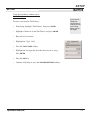
An access code must be entered before the installation setup
parameters can be accessed or changed.
IMPORTANT
The access code is 8891.
Refer to Section 7, Setup.
IMPORTANT
Supervisors may wish to remove this page from the MILLPWR
Operation Manual after initially setting up the installation setup
parameters. Keep it in a safe place for future use.
TABLE OF CONTENTS
MILLPWR
®
Introduction . . . . . . . . . . . . . . . . . . . . . . . . . . . . . . . . . . . . . . . . . . . . . . . . . .1-1
System Overview . . . . . . . . . . . . . . . . . . . . . . . . . . . . . . . . . . . . . . . . . . .1-1
Operator Console Overview . . . . . . . . . . . . . . . . . . . . . . . . . . . . . . . .1-2
Keypad Layout . . . . . . . . . . . . . . . . . . . . . . . . . . . . . . . . . . . . . . . . .1-3
Screen Layout . . . . . . . . . . . . . . . . . . . . . . . . . . . . . . . . . . . . . . . . . .1-4
Table Stop Button . . . . . . . . . . . . . . . . . . . . . . . . . . . . . . . . . . . . . . .1-5
Conventions . . . . . . . . . . . . . . . . . . . . . . . . . . . . . . . . . . . . . . . . . . . . . .1-6
Axis Conventions . . . . . . . . . . . . . . . . . . . . . . . . . . . . . . . . . . . . . . . .1-6
Count Direction . . . . . . . . . . . . . . . . . . . . . . . . . . . . . . . . . . . . . .1-6
Cartesian Coordinates . . . . . . . . . . . . . . . . . . . . . . . . . . . . . . . . . .1-7
Polar Coordinates . . . . . . . . . . . . . . . . . . . . . . . . . . . . . . . . . . . . .1-7
Absolute and Incremental Dimensions . . . . . . . . . . . . . . . . . . . . . .1-8
Z-axis Conventions . . . . . . . . . . . . . . . . . . . . . . . . . . . . . . . . . . . . . . .1-9
Z-axis Retract . . . . . . . . . . . . . . . . . . . . . . . . . . . . . . . . . . . . . . . .1-9
Begin and End Depths . . . . . . . . . . . . . . . . . . . . . . . . . . . . . . . . . .1-9
Pass . . . . . . . . . . . . . . . . . . . . . . . . . . . . . . . . . . . . . . . . . . . . . . . .1-9
Disengaging the Z-axis Drive System . . . . . . . . . . . . . . . . . . . . . .1-10
Setting Z-axis Datum when Changing Tools . . . . . . . . . . . . . . . . . . . .1-12
Drilling Conventions . . . . . . . . . . . . . . . . . . . . . . . . . . . . . . . . . . . . . .1-12
Peck . . . . . . . . . . . . . . . . . . . . . . . . . . . . . . . . . . . . . . . . . . . . . . .1-12
Tool Retract . . . . . . . . . . . . . . . . . . . . . . . . . . . . . . . . . . . . . . . . .1-12
Dwell . . . . . . . . . . . . . . . . . . . . . . . . . . . . . . . . . . . . . . . . . . . . . .1-12
Saving, Backing Up, and Creating Directories . . . . . . . . . . . . . . . . . .1-13
DRO . . . . . . . . . . . . . . . . . . . . . . . . . . . . . . . . . . . . . . . . . . . . . . . . . . . . . . . . .2-1
Start Up . . . . . . . . . . . . . . . . . . . . . . . . . . . . . . . . . . . . . . . . . . . . . . . . . .2-1
Power Up . . . . . . . . . . . . . . . . . . . . . . . . . . . . . . . . . . . . . . . . . . . . . .2-1
Screen Saver . . . . . . . . . . . . . . . . . . . . . . . . . . . . . . . . . . . . . . . . . . . .2-1
Finding Home . . . . . . . . . . . . . . . . . . . . . . . . . . . . . . . . . . . . . . . . . . .2-2
DRO Functions . . . . . . . . . . . . . . . . . . . . . . . . . . . . . . . . . . . . . . . . . . . . .2-4
Move Table . . . . . . . . . . . . . . . . . . . . . . . . . . . . . . . . . . . . . . . . . . . . .2-4
Zeroing an Axis . . . . . . . . . . . . . . . . . . . . . . . . . . . . . . . . . . . . . . . . .2-5
Inch/millimeter . . . . . . . . . . . . . . . . . . . . . . . . . . . . . . . . . . . . . . . . . .2-5
Teach Position . . . . . . . . . . . . . . . . . . . . . . . . . . . . . . . . . . . . . . . . . .2-5
Using an Electronic Edge Finder . . . . . . . . . . . . . . . . . . . . . . . . . . . .2-6
Skewing a Part . . . . . . . . . . . . . . . . . . . . . . . . . . . . . . . . . . . . . . . . . .2-7
Establishing Datum . . . . . . . . . . . . . . . . . . . . . . . . . . . . . . . . . . . . . . .2-9
Hard Key Milling Functions . . . . . . . . . . . . . . . . . . . . . . . . . . . . . . .2-12
Operation Manual
i
TABLE OF CONTENTS
MILLPWR ®
Programming . . . . . . . . . . . . . . . . . . . . . . . . . . . . . . . . . . . . . . . . . . . . . . . . .3-1
Programming Considerations . . . . . . . . . . . . . . . . . . . . . . . . . . . . . . . . . .3-1
“From” and “To” Points . . . . . . . . . . . . . . . . . . . . . . . . . . . . . . . . . . .3-1
Depth of Cut . . . . . . . . . . . . . . . . . . . . . . . . . . . . . . . . . . . . . . . . . . .3-1
Pass . . . . . . . . . . . . . . . . . . . . . . . . . . . . . . . . . . . . . . . . . . . . . . . . . .3-1
Tool Offset . . . . . . . . . . . . . . . . . . . . . . . . . . . . . . . . . . . . . . . . . . . . .3-2
Datum Selection . . . . . . . . . . . . . . . . . . . . . . . . . . . . . . . . . . . . . . . .3-2
Absolute and Incremental Dimensions . . . . . . . . . . . . . . . . . . . . . . . . . . .3-3
Continuous Milling . . . . . . . . . . . . . . . . . . . . . . . . . . . . . . . . . . . . . .3-3
Creating a Program . . . . . . . . . . . . . . . . . . . . . . . . . . . . . . . . . . . . . . . . .3-5
The View Key . . . . . . . . . . . . . . . . . . . . . . . . . . . . . . . . . . . . . . . . . .3-7
Follow Tool . . . . . . . . . . . . . . . . . . . . . . . . . . . . . . . . . . . . . . . . . .3-7
Show Tool Path . . . . . . . . . . . . . . . . . . . . . . . . . . . . . . . . . . . . . . .3-7
Zoom In, Zoom Out and Restore . . . . . . . . . . . . . . . . . . . . . . . . . .3-7
Running a Program . . . . . . . . . . . . . . . . . . . . . . . . . . . . . . . . . . . . . . . . .3-8
Skewing a Part . . . . . . . . . . . . . . . . . . . . . . . . . . . . . . . . . . . . . . . . . .3-8
Establishing Datum . . . . . . . . . . . . . . . . . . . . . . . . . . . . . . . . . . . . . . .3-10
Testing Your MILLPWR Program . . . . . . . . . . . . . . . . . . . . . . . . . . . .3-13
Single Step . . . . . . . . . . . . . . . . . . . . . . . . . . . . . . . . . . . . . . . . . .3-13
Dry Run . . . . . . . . . . . . . . . . . . . . . . . . . . . . . . . . . . . . . . . . . . . .3-13
Graphics Only . . . . . . . . . . . . . . . . . . . . . . . . . . . . . . . . . . . . . . . .3-13
Manual Positioning . . . . . . . . . . . . . . . . . . . . . . . . . . . . . . . . . . . .3-14
Disable Look Ahead . . . . . . . . . . . . . . . . . . . . . . . . . . . . . . . . . . .3-14
Machining Your Part . . . . . . . . . . . . . . . . . . . . . . . . . . . . . . . . . . . . . .3-15
Feed + and Feed - . . . . . . . . . . . . . . . . . . . . . . . . . . . . . . . . . . . . . . .3-16
Manually Positioning the Quill . . . . . . . . . . . . . . . . . . . . . . . . . . . . .3-16
Program Functions . . . . . . . . . . . . . . . . . . . . . . . . . . . . . . . . . . . . . . . . . .3-17
Directories . . . . . . . . . . . . . . . . . . . . . . . . . . . . . . . . . . . . . . . . . . . . .3-18
Creating a Sub-directory . . . . . . . . . . . . . . . . . . . . . . . . . . . . . . .3-19
Selecting a Directory . . . . . . . . . . . . . . . . . . . . . . . . . . . . . . . . . .3-21
Deleting a Directory . . . . . . . . . . . . . . . . . . . . . . . . . . . . . . . . . . .3-23
Saving a Program . . . . . . . . . . . . . . . . . . . . . . . . . . . . . . . . . . . . . . . .3-24
Naming a Program . . . . . . . . . . . . . . . . . . . . . . . . . . . . . . . . . . . . . . .3-25
Loading a MILLPWR (MPT) Program . . . . . . . . . . . . . . . . . . . . . . . .3-26
From MILLPWR's internal memory . . . . . . . . . . . . . . . . . . . . . . . . .3-26
From a 31/2" floppy disk . . . . . . . . . . . . . . . . . . . . . . . . . . . . . . . .3-27
From your PC . . . . . . . . . . . . . . . . . . . . . . . . . . . . . . . . . . . . . . .3-28
Translating a DXF file . . . . . . . . . . . . . . . . . . . . . . . . . . . . . . . . . . . .3-28
ii
Operation Manual
TABLE OF CONTENTS
MILLPWR
®
Loading a G-code file . . . . . . . . . . . . . . . . . . . . . . . . . . . . . . . . . . . . .3-29
Running a G-code Program . . . . . . . . . . . . . . . . . . . . . . . . . . . . . . . . .3-31
MILLPWR - G-code Conventions . . . . . . . . . . . . . . . . . . . . . . . . . . . . .3-33
Merging Programs . . . . . . . . . . . . . . . . . . . . . . . . . . . . . . . . . . . . . . .3-37
Backing Up a Program . . . . . . . . . . . . . . . . . . . . . . . . . . . . . . . . . . . .3-38
Deleting a Program . . . . . . . . . . . . . . . . . . . . . . . . . . . . . . . . . . . . . .3-39
Demonstration Program . . . . . . . . . . . . . . . . . . . . . . . . . . . . . . . . . . . . . . .4-1
Selecting Datum . . . . . . . . . . . . . . . . . . . . . . . . . . . . . . . . . . . . . . . . . . .4-1
Beginning the Program . . . . . . . . . . . . . . . . . . . . . . . . . . . . . . . . . . . . . .4-2
Selecting a Tool . . . . . . . . . . . . . . . . . . . . . . . . . . . . . . . . . . . . . . . . .4-2
Programming the Contour . . . . . . . . . . . . . . . . . . . . . . . . . . . . . . . . .4-4
Programming the Bolthole Pattern . . . . . . . . . . . . . . . . . . . . . . . . . . .4-12
Programming the Rectangular Pocket . . . . . . . . . . . . . . . . . . . . . . . . .4-15
Saving Your Program . . . . . . . . . . . . . . . . . . . . . . . . . . . . . . . . . . . . . . . .4-17
Testing Your Program . . . . . . . . . . . . . . . . . . . . . . . . . . . . . . . . . . . . . . .4-18
Running the Program . . . . . . . . . . . . . . . . . . . . . . . . . . . . . . . . . . . . . . . .4-19
Tool Changes . . . . . . . . . . . . . . . . . . . . . . . . . . . . . . . . . . . . . . . . . . . . . .4-20
Clearing the Program . . . . . . . . . . . . . . . . . . . . . . . . . . . . . . . . . . . . . . . .4-20
Program Steps . . . . . . . . . . . . . . . . . . . . . . . . . . . . . . . . . . . . . . . . . . . . . . . .5-1
Simple Milling and Drilling . . . . . . . . . . . . . . . . . . . . . . . . . . . . . . . . . . .5-1
Programming a Tool Step w/Repeatable Tool Length Offsets . . . . . . .5-2
Entering the First Tool . . . . . . . . . . . . . . . . . . . . . . . . . . . . . . . . . . . .5-2
Changing to a Tool of Unknown Length in the DRO . . . . . . . . . . . . . .5-4
Changing to a Tool Of Unknown Length in PGM . . . . . . . . . . . . . . . .5-4
Position/Drill . . . . . . . . . . . . . . . . . . . . . . . . . . . . . . . . . . . . . . . . . . .5-6
Centerline . . . . . . . . . . . . . . . . . . . . . . . . . . . . . . . . . . . . . . . . . . . . . .5-7
Line . . . . . . . . . . . . . . . . . . . . . . . . . . . . . . . . . . . . . . . . . . . . . . . . . .5-8
Arc . . . . . . . . . . . . . . . . . . . . . . . . . . . . . . . . . . . . . . . . . . . . . . . . . . .5-9
Blend . . . . . . . . . . . . . . . . . . . . . . . . . . . . . . . . . . . . . . . . . . . . . . . . .5-11
Rectangular Milling Functions . . . . . . . . . . . . . . . . . . . . . . . . . . . . . . . . .5-13
Pocket . . . . . . . . . . . . . . . . . . . . . . . . . . . . . . . . . . . . . . . . . . . . . . . . .5-13
Frame . . . . . . . . . . . . . . . . . . . . . . . . . . . . . . . . . . . . . . . . . . . . . . . . .5-16
Face . . . . . . . . . . . . . . . . . . . . . . . . . . . . . . . . . . . . . . . . . . . . . . . . . .5-18
Slot . . . . . . . . . . . . . . . . . . . . . . . . . . . . . . . . . . . . . . . . . . . . . . . . . . .5-20
Operation Manual
iii
TABLE OF CONTENTS
MILLPWR ®
Circular Milling Functions . . . . . . . . . . . . . . . . . . . . . . . . . . . . . . . . . . . .5-22
Pocket . . . . . . . . . . . . . . . . . . . . . . . . . . . . . . . . . . . . . . . . . . . . . . . . .5-22
Frame . . . . . . . . . . . . . . . . . . . . . . . . . . . . . . . . . . . . . . . . . . . . . . . . .5-24
Ring . . . . . . . . . . . . . . . . . . . . . . . . . . . . . . . . . . . . . . . . . . . . . . . . . .5-26
Helix . . . . . . . . . . . . . . . . . . . . . . . . . . . . . . . . . . . . . . . . . . . . . . . . . .5-28
Hole Patterns . . . . . . . . . . . . . . . . . . . . . . . . . . . . . . . . . . . . . . . . . . . . . .5-30
Row of Holes . . . . . . . . . . . . . . . . . . . . . . . . . . . . . . . . . . . . . . . . . . .5-30
Hole Frame and Hole Array . . . . . . . . . . . . . . . . . . . . . . . . . . . . . . . .5-32
Bolthole Circle Patterns . . . . . . . . . . . . . . . . . . . . . . . . . . . . . . . . . . .5-35
Additional Milling Functions . . . . . . . . . . . . . . . . . . . . . . . . . . . . . . . . . .5-37
Custom Pocket . . . . . . . . . . . . . . . . . . . . . . . . . . . . . . . . . . . . . . . . . .5-37
Repeat . . . . . . . . . . . . . . . . . . . . . . . . . . . . . . . . . . . . . . . . . . . . . . . .5-39
Rotate . . . . . . . . . . . . . . . . . . . . . . . . . . . . . . . . . . . . . . . . . . . . . . . .5-40
Mirror . . . . . . . . . . . . . . . . . . . . . . . . . . . . . . . . . . . . . . . . . . . . . . . .5-41
Contour . . . . . . . . . . . . . . . . . . . . . . . . . . . . . . . . . . . . . . . . . . . . . . .5-42
Engrave . . . . . . . . . . . . . . . . . . . . . . . . . . . . . . . . . . . . . . . . . . . . . . .5-44
Engrave Line . . . . . . . . . . . . . . . . . . . . . . . . . . . . . . . . . . . . . . . .5-44
Engrave Arc . . . . . . . . . . . . . . . . . . . . . . . . . . . . . . . . . . . . . . . . .5-47
Ellipse Frame . . . . . . . . . . . . . . . . . . . . . . . . . . . . . . . . . . . . . . . . . . .5-49
Chamfer . . . . . . . . . . . . . . . . . . . . . . . . . . . . . . . . . . . . . . . . . . . . . . .5-51
Reference Point . . . . . . . . . . . . . . . . . . . . . . . . . . . . . . . . . . . . . . . . . .5-53
Island . . . . . . . . . . . . . . . . . . . . . . . . . . . . . . . . . . . . . . . . . . . . . . . . .5-54
Spiral . . . . . . . . . . . . . . . . . . . . . . . . . . . . . . . . . . . . . . . . . . . . . . . . .5-55
Comment Step . . . . . . . . . . . . . . . . . . . . . . . . . . . . . . . . . . . . . . . . . .5-57
Auxiliary Function (AMI Option) . . . . . . . . . . . . . . . . . . . . . . . . . . . .5-58
Step Functions Softkey . . . . . . . . . . . . . . . . . . . . . . . . . . . . . . . . . . . . . . .5-60
Explode . . . . . . . . . . . . . . . . . . . . . . . . . . . . . . . . . . . . . . . . . . . . . . .5-60
Reverse Step . . . . . . . . . . . . . . . . . . . . . . . . . . . . . . . . . . . . . . . . . . . .5-62
Reverse Path . . . . . . . . . . . . . . . . . . . . . . . . . . . . . . . . . . . . . . . . . . . .5-62
Change Steps . . . . . . . . . . . . . . . . . . . . . . . . . . . . . . . . . . . . . . . . . . .5-63
Delete Steps . . . . . . . . . . . . . . . . . . . . . . . . . . . . . . . . . . . . . . . . . . . .5-64
Copy/Move Steps . . . . . . . . . . . . . . . . . . . . . . . . . . . . . . . . . . . . . . . .5-65
Calculator . . . . . . . . . . . . . . . . . . . . . . . . . . . . . . . . . . . . . . . . . . . . . . . . . . . .6-1
Math Functions (+, -, ÷, x) . . . . . . . . . . . . . . . . . . . . . . . . . . . . . . . . . . . .6-2
Trig Functions . . . . . . . . . . . . . . . . . . . . . . . . . . . . . . . . . . . . . . . . . . . . .6-2
Geometry Functions . . . . . . . . . . . . . . . . . . . . . . . . . . . . . . . . . . . . . . . .6-4
iv
Operation Manual
TABLE OF CONTENTS
MILLPWR
®
Working with the Geometry Calculator . . . . . . . . . . . . . . . . . . . . . . .6-4
GeoCalc™ Quick Reference Table . . . . . . . . . . . . . . . . . . . . . . . . . . . .6-5
Using GeoCalc . . . . . . . . . . . . . . . . . . . . . . . . . . . . . . . . . . . . . . . . . .6-6
Calculator Functions . . . . . . . . . . . . . . . . . . . . . . . . . . . . . . . . . . . . . .6-7
Saving Results Calculated in GeoCalc . . . . . . . . . . . . . . . . . . . . . .6-7
Loading GeoCalc Results That You Previously Saved . . . . . . . . .6-8
Loading Programs into GeoCalc . . . . . . . . . . . . . . . . . . . . . . . . . .6-9
Clearing GeoCalc . . . . . . . . . . . . . . . . . . . . . . . . . . . . . . . . . . . . .6-9
Example Problem . . . . . . . . . . . . . . . . . . . . . . . . . . . . . . . . . . . . . . . . . .6-10
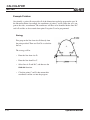
Strategy . . . . . . . . . . . . . . . . . . . . . . . . . . . . . . . . . . . . . . . . . . . .6-10
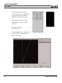
Starting the Program . . . . . . . . . . . . . . . . . . . . . . . . . . . . . . . . . .6-11
Entering the Lines . . . . . . . . . . . . . . . . . . . . . . . . . . . . . . . . .6-11
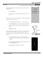
Finding the Arc . . . . . . . . . . . . . . . . . . . . . . . . . . . . . . . . . . .6-14
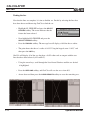
Finding the Points of Tangency . . . . . . . . . . . . . . . . . . . . . . . .6-15
Returning Features . . . . . . . . . . . . . . . . . . . . . . . . . . . . . . . . .6-16
RPM Functions . . . . . . . . . . . . . . . . . . . . . . . . . . . . . . . . . . . . . . . . . . . . .6-18
Setup . . . . . . . . . . . . . . . . . . . . . . . . . . . . . . . . . . . . . . . . . . . . . . . . . . . . . . . . .7-1
Job Setup . . . . . . . . . . . . . . . . . . . . . . . . . . . . . . . . . . . . . . . . . . . . . . . . .7-2
Tool Library . . . . . . . . . . . . . . . . . . . . . . . . . . . . . . . . . . . . . . . . . . . .7-2
Using the Tool Library with Tool length offsets . . . . . . . . . . . . . . . . .7-4
Entering the First Tool . . . . . . . . . . . . . . . . . . . . . . . . . . . . . . . . . .7-5
Using the Tool Library . . . . . . . . . . . . . . . . . . . . . . . . . . . . . . . . .7-7
Scale Factor . . . . . . . . . . . . . . . . . . . . . . . . . . . . . . . . . . . . . . . . . . . .7-11
Display Options . . . . . . . . . . . . . . . . . . . . . . . . . . . . . . . . . . . . . . . . .7-12
Angles . . . . . . . . . . . . . . . . . . . . . . . . . . . . . . . . . . . . . . . . . . . . . .7-12
INC Display . . . . . . . . . . . . . . . . . . . . . . . . . . . . . . . . . . . . . . . . .7-12
Display Resolution . . . . . . . . . . . . . . . . . . . . . . . . . . . . . . . . . . . .7-12
Point Entry . . . . . . . . . . . . . . . . . . . . . . . . . . . . . . . . . . . . . . . . . .7-12
“From” Point . . . . . . . . . . . . . . . . . . . . . . . . . . . . . . . . . . . . . . . . .7-13
Stepover Entry . . . . . . . . . . . . . . . . . . . . . . . . . . . . . . . . . . . . . . .7-13
Pass/Peck/Retract . . . . . . . . . . . . . . . . . . . . . . . . . . . . . . . . . . . . .7-13
Electronic Edge Finder . . . . . . . . . . . . . . . . . . . . . . . . . . . . . . . . . . . .7-14
Job Clock . . . . . . . . . . . . . . . . . . . . . . . . . . . . . . . . . . . . . . . . . . . . . .7-14
Feed Rate Settings . . . . . . . . . . . . . . . . . . . . . . . . . . . . . . . . . . . . . . .7-16
Step Override % . . . . . . . . . . . . . . . . . . . . . . . . . . . . . . . . . . . . . .7-16
Max % . . . . . . . . . . . . . . . . . . . . . . . . . . . . . . . . . . . . . . . . . . . . .7-16
Operation Manual
v
TABLE OF CONTENTS
MILLPWR ®
Min % . . . . . . . . . . . . . . . . . . . . . . . . . . . . . . . . . . . . . . . . . . . . . .7-16
Dry Run Speed . . . . . . . . . . . . . . . . . . . . . . . . . . . . . . . . . . . . . . .7-16
Default Feed Rate . . . . . . . . . . . . . . . . . . . . . . . . . . . . . . . . . . . . .7-16
Unit/(Min) . . . . . . . . . . . . . . . . . . . . . . . . . . . . . . . . . . . . . . . . . . .7-16
Full Cut Feed Rate % . . . . . . . . . . . . . . . . . . . . . . . . . . . . . . . . . .7-16
Installation Setup . . . . . . . . . . . . . . . . . . . . . . . . . . . . . . . . . . . . . . . . . . .7-17
Protection . . . . . . . . . . . . . . . . . . . . . . . . . . . . . . . . . . . . . . . . . . . . .7-17
Error Compensation . . . . . . . . . . . . . . . . . . . . . . . . . . . . . . . . . . . . . .7-18
Encoder Setup . . . . . . . . . . . . . . . . . . . . . . . . . . . . . . . . . . . . . . . . . . .7-19
Travel Limits . . . . . . . . . . . . . . . . . . . . . . . . . . . . . . . . . . . . . . . . . . .7-21
Error Checking . . . . . . . . . . . . . . . . . . . . . . . . . . . . . . . . . . . . . . . . . .7-22
Serial Port . . . . . . . . . . . . . . . . . . . . . . . . . . . . . . . . . . . . . . . . . . . . .7-23
Z-axis Control . . . . . . . . . . . . . . . . . . . . . . . . . . . . . . . . . . . . . . . . . . .7-23
Spindle Control . . . . . . . . . . . . . . . . . . . . . . . . . . . . . . . . . . . . . . .7-24
Error Log . . . . . . . . . . . . . . . . . . . . . . . . . . . . . . . . . . . . . . . . . . .7-24
Servo Tuning . . . . . . . . . . . . . . . . . . . . . . . . . . . . . . . . . . . . . . . .7-25
Automatically Tuning the Servo in Console Mode . . . . . . . . . . . . .7-26
AMI Outputs . . . . . . . . . . . . . . . . . . . . . . . . . . . . . . . . . . . . . . . . .7-28
Diagnostics . . . . . . . . . . . . . . . . . . . . . . . . . . . . . . . . . . . . . . . . . .7-29
Motor Assembly Monitor . . . . . . . . . . . . . . . . . . . . . . . . . . . . .7-30
Signal Test . . . . . . . . . . . . . . . . . . . . . . . . . . . . . . . . . . . . . . . .7-31
Table Stop Test . . . . . . . . . . . . . . . . . . . . . . . . . . . . . . . . . . . .7-32
Circle Interpolation Test . . . . . . . . . . . . . . . . . . . . . . . . . . . . .7-33
Examples of Circle Interpolation Test Results . . . . . . . . . . .7-34
Keypad Test . . . . . . . . . . . . . . . . . . . . . . . . . . . . . . . . . . . . . . .7-35
Display Test . . . . . . . . . . . . . . . . . . . . . . . . . . . . . . . . . . . . . . .7-36
Disk Utilization . . . . . . . . . . . . . . . . . . . . . . . . . . . . . . . . . . . .7-37
Set Time and Date . . . . . . . . . . . . . . . . . . . . . . . . . . . . . . . . . .7-38
System Statistics . . . . . . . . . . . . . . . . . . . . . . . . . . . . . . . . . . .7-38
Max Servo Speed . . . . . . . . . . . . . . . . . . . . . . . . . . . . . . . . . . . . .7-39
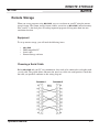
Remote Storage . . . . . . . . . . . . . . . . . . . . . . . . . . . . . . . . . . . . . . . . . . . . . . .8-1
Equipment . . . . . . . . . . . . . . . . . . . . . . . . . . . . . . . . . . . . . . . . . . . . . . . .8-1
Choosing a Serial Cable . . . . . . . . . . . . . . . . . . . . . . . . . . . . . . . . . . . . . .8-1
vi
Operation Manual
TABLE OF CONTENTS
MILLPWR
®
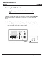
Connecting MILLPWR to Your PC . . . . . . . . . . . . . . . . . . . . . . . . . . . . . . . 8-2
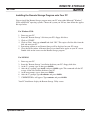
Installing the Remote Storage Program onto Your PC . . . . . . . . . . . . . 8-3
For Windows 95 and 98 . . . . . . . . . . . . . . . . . . . . . . . . . . . . . . . . . . .8-3
For MS DOS . . . . . . . . . . . . . . . . . . . . . . . . . . . . . . . . . . . . . . . . . . . 8-3
Setting Up Your COM Port and BAUD Rates . . . . . . . . . . . . . . . . . . . . . .8-4
Activating the Remote Storage Feature in MILLPWR . . . . . . . . . . . . . . . . .8-5
Troubleshooting . . . . . . . . . . . . . . . . . . . . . . . . . . . . . . . . . . . . . . . . . . . .8-5
®
®
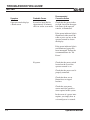
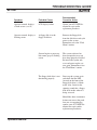
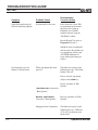
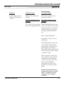
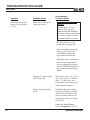
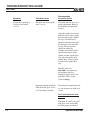
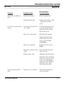
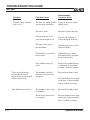
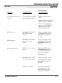
Troubleshooting Guide . . . . . . . . . . . . . . . . . . . . . . . . . . . . . . . . . . . . . . . .9-1
Introduction . . . . . . . . . . . . . . . . . . . . . . . . . . . . . . . . . . . . . . . . . . . . . . .9-1
Using the Table . . . . . . . . . . . . . . . . . . . . . . . . . . . . . . . . . . . . . . . . . . . . .9-1
Table . . . . . . . . . . . . . . . . . . . . . . . . . . . . . . . . . . . . . . . . . . . . . . . . . . .9-2
Re-aligning (Tramming) the Spindle . . . . . . . . . . . . . . . . . . . . . . . . . . . . .9-15
2013-178 Ed. A
Operation Manual
vii
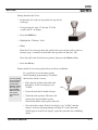
This symbol alerts you to important information
concerning the operation of your MILLPWR system.
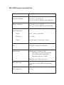
MILLPWR System Specifications
Characteristic
Specification
Operating conditions
0° to 40° C (32° to 104° F)
25% to 85% relative humidity (non-condensing)
Storage conditions
-20° to 60° C (-4° to 140° F)
25% to 95% relative humidty (non-condensing)
Input requirements:
Voltage
115V~ (±20%), single phase
Frequency
47 - 63 Hz
Current
8.5A rms nom., 18A rms peak—inrush
Fuse
15A/250V resettable circuit breaker
Encoder input
Position signals, channels A & B
TTL square wave signal in quadrature
(90° nominal phase relationship)
Maximum input rate: 50 kHz
Reference signal: TTL square wave
Edge finder input
Compatible with ACU-RITE Electronic Edge
Finder
FCC compliance
Class A
®
INTRODUCTION
MILLPWR
®
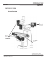
INTRODUCTION
System Overview
Operator
Console
Motor
Drive
Assemblies
ACU-RITE™
Scales
Licensed under U. S. Patent No. 5,941,663
(applies to Linear Encoder systems with Z-axis only)
Operation Manual
1-1
INTRODUCTION
MILLPWR ®
Front View of Operator Console
Rear View of Operator Console
1-2
Operation Manual
INTRODUCTION
MILLPWR
®
Keypad Layout
Main Function Keys
Cursor and Motion Control
Switch from absolute to incremental
(or vice versa) in the DRO display and
milling function numeric fields.
Manipulate your part graphic.
GO
Start your program.
STOP
Press this key once to pause
your program, twice to exit.
FEED+
FEED-
Increase or decrease your feed
rate.
Display the digital readout.
Display the program screen.
Exit from a milling function.
Add a step to your program once
you’ve completed an entry form.
Special Function Keys
INFO
Access information about any
MILLPWR function.
MM
Switch from inches to
millimeters or vice versa.
SETUP
Add to your tool library, set
your feed rates, change
your display options and
define other system parameters.
CALC
Operation Manual
Perform standard (+, -, x, ÷),
trigonometry, geometry and
RPM calculations.
ARROWS These keys enable you to position your table or move your
cursor.
Milling Functions
Use these keys to create a program. All but
BLEND may also be used as one-time milling
functions from the DRO display.
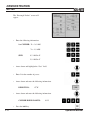
Numeric Keypad and Calculator
Enter program data and
perform math calculations. Press the CLEAR
key to delete information from a data field.
Press the ENTER key
to accept the information you’ve entered.
1-3
INTRODUCTION
MILLPWR ®
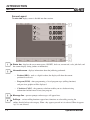
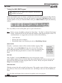
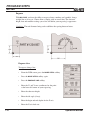
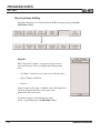
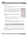
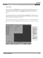
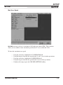
Screen Layout
The MILLPWR display screen is divided into four sections.
Status bar - displays the servo motor status (ON/OFF), feed rate, current tool, scale, job clock, and
the current display setting (inches or millimeters).
Information area - displays information about the job being performed.
•
Readout (DRO) - used as a digital readout, the display will show the current
position for each axis.
•
Program (PGM) - when programming, a list of program steps (milling functions)
and part-view graphics will be displayed.
•
Calculator (CALC) - the geometry calculator enables you to calculate missing
information and then insert it into your program.
Message line - operator prompts and messages will appear here.
Softkeys - various milling functions appear here; functions are selected by pressing the
softkey directly below each category. When a key appears pressed in it is selected. When it appears
“up” it is not selected.
1-4
Operation Manual
INTRODUCTION
MILLPWR
®
Table Stop Button
The large red button located in the lower left corner on the front of your MILLPWR operator
console is the TABLE STOP. In the event of a malfunction or programming error, press the
TABLE STOP button to turn off the servo motors. This will immediately stop all positioning for
each axis.
WARNING!
Pressing the TABLE STOP button will NOT stop the rotation of
the cutting tool unless your machine has been configured to do
so. If your machine has not been wired to stop the rotation of the
cutting tool, be prepared to raise the tool and power down the
spindle in addition to pressing the TABLE STOP button.
Operation Manual
1-5
INTRODUCTION
MILLPWR ®
Conventions
Axis Conventions
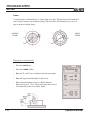
Count Direction
When programming a part using MILLPWR, table movement and tool movement are
determined by the use of positive or negative numbers. MILLPWR has been factory
set with the following positive and negative count
directions for the X, Y and Z-axes:
X-axis: The table will move to the left and the
tool will move to the right for a
positive count direction.
Y-axis: The table will move toward you while
the tool moves away from you for a
positive count direction.
Z-axis: The quill will move up (away from
the table surface) for a positive count
direction.
1-6
Operation Manual
INTRODUCTION
MILLPWR
®
Cartesian Coordinates
A cartesian coordinate is a position that can be measured from the X- and Y-axes.
Polar Coordinates
A polar coordinate is a position that is defined by an angle and a radius.
Operation Manual
1-7
INTRODUCTION
MILLPWR ®
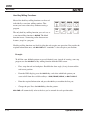
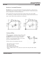
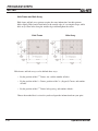
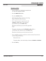
Absolute and Incremental Dimensions
Dimensions that you enter from a print are
either absolute or incremental.
Absolute dimensions are measured
from datum (also known as workpiece
zero). Incremental dimensions are
measured from one point to another.
Holes A and B are dimensioned using
absolute values. Hole C is dimensioned
incrementally from Hole A.
When entering these dimensions, we would say:
Hole A: 002 Position/Drill
X 2.0000 ABS
Y 1.5000 ABS
Hole B: 003 Position/Drill
X 4.0000 ABS
Y 1.5000 ABS
Hole C: 004 Position/Drill
X 3.6250 INC 002 Y 1.5000 ABS
This indicates that the X position will
increment from the X value in Step 2.
Note: Both absolute and incremental dimensions may be used to define a position,
as shown with Hole C.
It’s often easier to describe a location in terms of incremental dimensions rather than
calculate its absolute coordinates.
1-8
Operation Manual
INTRODUCTION
MILLPWR
®
Z-axis Conventions
Z-axis Retract
The Z-axis retract is the position the quill returns to between program steps. By setting a
retract position, you can ensure that the tool you are using does not make contact with your
workpiece when the quill moves from one position to the next. It’s a good idea to establish a
retract position for the Z-axis each time you power up your system; otherwise, MILLPWR
will use the quill’s upper travel limit as the Z-axis retract position.
Note: Loading a PGM will reset the Z-axis retract to the Z upper limit.
Note: If your tool is above the Z-axis retract position when you run a program, the table
will rapidly move to position, and then the quill will rapidly move down to the
retract position. If the tool is below the retract position, the quill will rapidly move
up to the retract position first, and then the table will rapidly move into position.
Begin and End Depths
The “Begin” and “End” depths determine where the tool will begin and end its cutting
motion. They may be specified as absolute (ABS) or incremental (INC) distances. If the
“Begin” field is left blank, you will be prompted to manually position the quill to the
desired depth.
Once the quill has reached its retract position, it will rapidly move to the “Begin” depth then
move at the programmed feed rate to the “End” depth.
If the travel limit for the Z-axis is set below the established retract position, a travel limit
fault will occur and the program will stop.
Pass
“Pass” refers to the number of cuts that are used to machine an area to its “End” depth. You
can control how frequently a pass occurs by entering a value in the “Pass” field whenever it
appears. (If you don’t want to program more than one pass, leave the field blank.)
Operation Manual
1-9
INTRODUCTION
MILLPWR ®
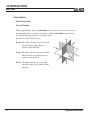
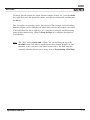
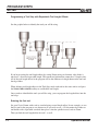
Disengaging the Z-axis Drive System (Rotary Encoder)
provides you with the flexibility to switch between twoaxes and three-axes operation.
MILLPWR
To disengage the Z-axis drive system from your MILLPWR
system:
•
Leave the “Begin” field blank when you program a step
or a one-time milling function.
•
Raise the quill, then loosen the quick release knob
located on the front of the Z-axis drive system.
•
When you run the program step or one-time milling
function, you will be prompted to manually position
the quill.
To re-engage the Z-axis drive system, lift the quill handle until you
feel the drive assembly become seated, then tighten the quick release knob.
The following Operator Intervention Messages (OIMs) apply to Rotary Encoders:
1-10
Operation Manual
INTRODUCTION
MILLPWR
®
Disengaging the Z-axis Drive System (Linear Encoder Option)
MILLPWR
provides you with the flexibility to switch between two-axes and three-axes operation.
To disengage the Z-axis drive system from your MILLPWR
system:
•
Leave the “Begin” field blank when you program a step
or a one-time milling function.
•
Raise the quill, then loosen the quick release knob
located on the front of the Z-axis drive system.
•
When you run the program step or one-time milling
function, you will be prompted to manually position
the quill.
To re-engage the Z-axis drive system, lift the quill handle until you feel the drive assembly become
seated, then tighten the quick release knob.
The following OIM apply to the optional Z-axis Linear Encoder (only):
Operation Manual
1-11
INTRODUCTION
MILLPWR ®
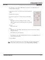
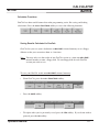
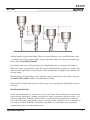
Setting Z-axis Datum when Changing Tools
Whenever you encounter a SET TOOL step, MILLPWR will display the DRO screen and let you know
which tool to load. If no tool diameter was programmed in the “Tool Step,” you will be prompted to
provide one.
•
Use the MOVE TABLE softkey and arrow keys to
move the tool away from your workpiece.
•
Press the move table softkey again to turn off the motors.
•
Insert the required tool into the spindle.
•
Using the MOVE TABLE feature, position the tool over
the surface of a known depth on your workpiece.
•
Press the DATUM softkey.
•
Position your tool so that it touches a known surface,
then enter that position into the Z-axis datum.
•
Press the USE key.
•
Raise the tool and press the GO key to continue the
program.
If the surface is at datum 0,
use the Z = 0 softkey.
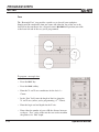
Drilling Conventions
Peck
“Hole” and “Position/Drill” steps give you the option of programming the quill to
“peck” or pause briefly. Peck cycles are used to break chips and reduce chip buildup
during drilling operations.
You can control how frequently a peck occurs by entering a value in the “Peck” field.
Tool Retract
Using the “Tool Retract” feature, you can program MILLPWR to raise the quill at a specified distance or frequency. This will allow the tool you’re drilling with to cool.
Dwell
“Dwell” is the length of time (in seconds) that the quill will pause during a tool retract.
1-12
Operation Manual
INTRODUCTION
MILLPWR
®
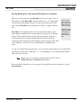
Saving, Backing Up, and Creating Directories for Programs
When you create programs with MILLPWR, you can save them in any of
three places—within MILLPWR's internal memory, on a 31/2" floppy disk,
or on your PC using Remote Storage. Saving your work means it will
not be lost if MILLPWR is powered down or if there is a power interruption.
is also equipped with a back up feature that enables you to
make duplicate copies of your saved programs to floppy disc or Remote
Storage. We recommend that you back up your programs regularly to
avoid accidental loss or other problems that may prevent you from
recovering your original programs. Backing up your programs takes only
a few moments—and will save you valuable time if a problem does
occur.
MILLPWR
If you’re creating a long program, don’t wait
until the end to
save your work.
Frequent saving
reduces the risk
of losing your
work due to a
power interruption.
As you save and back up your programs, you can neatly organize them in any of the following three main directories ("MILLPWR," "A:" and "REMTSTOR") or in personalized subdirectories that you can create.
Note: Before you save or back up programs onto your PC, refer to
Remote Storage and Setup for instructions.
For more details about how to save programs, back up files and create directories, refer to
Programming.
Operation Manual
1-13
DRO
MILLPWR
®
DRO
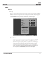
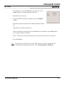
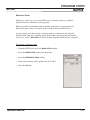
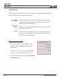
Start Up
Power Up
Press the power switch (located on the rear of the operator console) to “I.” The Power
Indicator (located in the upper left corner of the operator console) will light up green.
Once MILLPWR has been powered up, the following screen will appear:
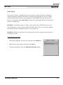
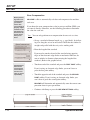
Screen Saver
Anytime your system is inactive for approximately 90 minutes, the LCD
display will shut off, and a blank screen will appear. This screen saver
function is designed to prolong the life of your operator console display.
If your screen is blank, check that the Power Indicator light is illuminated. Press any key on the operator console or move the table and the
display will reappear. If the Power Indicator light is not illuminated yellow, then power to your MILLPWR system has been interrupted.
Operation Manual
2-1
DRO
MILLPWR ®
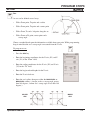
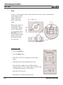
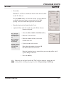
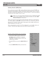
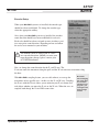
Finding Home (Rotary Encoder)
If you don't find home before moving the table, you will
risk exceeding the table's travel limits and damaging the
milling machine, MILLPWR or both.
You must find home before you run a program. To find home immediately after startup,
locate the Z-axis at the top of the fixed mark then press the FIND HOME softkey.
Otherwise, press the DATUM softkey, then the FIND HOME softkey. The table will automatically move a short distance along the Z-, Y- and then X-axes to find home. Z-axis
finds home first. You will have to locate the Z-axis at the top of the location mark before
finding home.
When finding home, MILLPWR will use ACU-RITE’s advanced Position-Trac™ technology. Position-Trac works by using a very precise distance-encrypted reference mark line
pattern that's been placed onto each ACU-RITE precision glass scale included with your
MILLPWR system. Proprietary software decodes the line pattern which then allows you to
accurately find home and reestablish workpiece zero from any position.
With Position-Trac, there is no need to leave the system powered up when it is not being
used. You’ll be able to easily, quickly and accurately reestablish workpiece zero after
power loss.
After home has been found, the tool’s position (relative to your most recent datum) will
be displayed.
2-2
Operation Manual
DRO
MILLPWR
®
Finding Home (Linear Encoder Option)
If you don't find home before moving the table, you will
risk exceeding the table's travel limits and damaging the
milling machine, MILLPWR or both.
You must find home before you run a program. To find home immediately after startup,
press the FIND HOME softkey. Otherwise, press the DATUM softkey, then the FIND HOME
softkey. The table will automatically move a few inches along the Z-, Y- and then X-axes
to find home.
When finding home, MILLPWR will use ACU-RITE’s advanced Position-Trac™ technology. Position-Trac works by using a very precise distance-encrypted reference mark line
pattern that's been placed onto each ACU-RITE precision glass scale included with your
MILLPWR system. Proprietary software decodes the line pattern which then allows you to
accurately find home and reestablish workpiece zero from any position.
With Position-Trac, there is no need to leave the system powered up when it is not being
used. You’ll be able to easily, quickly and accurately reestablish workpiece zero after
power loss.
After home has been found, the tool’s position (relative to your most recent datum) will
be displayed.
Datum is a
term used to
describe "workpiece zero" or
"absolute zero."
After you power
up and find
home, you
can quickly
move to datum
by pressing the
POS key, followed by the
GO key!
Operation Manual
2-3
DRO
MILLPWR ®
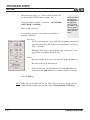
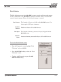
DRO Functions
The digital readout (DRO) display shows you the current tool position. While
operating in the DRO mode, you can use several functions, such as skew and
datum, to set up your job. You can also use this as a standard DRO when you use
your machine manually.
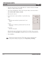
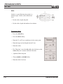
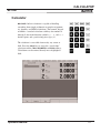
Move Table
The move table feature lets you move the table rapidly (or at an established feed rate)
using the arrow keys.
2-4
•
Press the MOVE TABLE softkey to turn the servo motors on. Press
it again to turn them off.
•
Enter the desired feed rate or skip this step to move at a rapid
feed rate.
•
If you want the arrow keys to move the table in increments, press
the 0.001, 0.01 or 0.1 softkey. (A different set of softkeys will
appear if you are measuring in millimeters.)
•
Move the table. You can move the X-, Y- and Z-axes simultaneously by pressing
two arrow keys and Z UP or Z DOWN softkeys at the same time.
•
Press the FEED+ and FEED- keys to adjust your feed rate.
It’s a good idea
to fold in the
handles before
moving the
table.
Operation Manual
DRO
MILLPWR
®
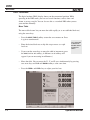
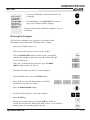
Zeroing an Axis
Pressing the ZERO X, ZERO Y or ZERO Z softkeys will zero the incremental position for
those axes.
You need to set datum to establish the point from which all absolute dimensions are
based.
Inch/millimeter
You can display inch or millimeter positions. Press the MM key to switch from one
to the other.
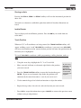
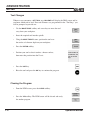
Teach Position
Whenever X, Y or Z coordinates are being entered, the TEACH POSITION softkey will
appear, enabling you to “teach” MILLPWR the coordinate(s) you want to use. MILLPWR
will base each coordinate on the current absolute position and enter that position into the
field that you’ve highlighted.
To “teach” MILLPWR a coordinate (while programming a milling function, such as a
line):
•
Using the arrow keys, highlight the X-, Y- or Z-axis field.
•
Move your tool, indicator, or electronic edge finder to the position
you want to teach.
As you’re programming, you
can switch
between the
DRO and PGM
screens without losing your
program.
•
Press the TEACH POSITION softkey to enter that location then press
ENTER. (If you use an electronic edge finder, the positions will
automatically be entered on contact—even if you over-travel.)
•
Use the numeric keypad and calculator functions to adjust the number.
·
Repeat the steps above for each axis and each location you want to teach.
·
Press USE to accept the information or press CANCEL to return to the previous screen
without saving teach position(s).
Operation Manual
2-5
DRO
MILLPWR ®
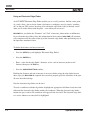
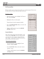
Using an Electronic Edge Finder
An ACU-RITE® Electronic Edge Finder enables you to “teach” positions, find the center point
of a circle, skew a part or locate datum (also known as workpiece zero) by simply “touching
off” on the part. The greatest advantage of an electronic edge finder is that it instantly senses
when you’ve made contact with the point —even when you over-travel.
lets you define the “Diameter” and “Unit” of measure (either inches or millimeters)
for an electronic edge finder. Once this information has been entered, MILLPWR will automatically compensate for the radius of the tip of the electronic edge finder when performing any of
the operations mentioned above.
MILLPWR
To define the diameter and unit of measure:
•
Press the SETUP key and highlight “Electronic Edge Finder.”
•
Press the ENTER key.
•
Enter a value for the edge finder’s diameter, select a unit of measure (inches or millimeters) then press the USE key.
•
Press the USE NEW SETTINGS softkey.
Defining the diameter and unit of measure is necessary before using the edge finder because
these steps give MILLPWR the required data it needs to properly place the centerline of the spindle over the indicated edge.
Now the electronic edge finder can be used.
To teach a coordinate with the edge finder, highlight the appropriate field then slowly move the
table until the electronic edge finder touches the workpiece. When the electronic edge finder
touches the part’s surface, the coordinate will appear in the data field. The electronic edge finder is active whenever an entry field is highlighted.
2-6
Operation Manual
DRO
MILLPWR
®
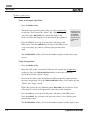
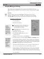
Skewing a Part
With MILLPWR, you can save time setting up a job by skewing your part. The skew function
automatically compensates for the offset angle of your part—so if your part is not perfectly
parallel with either the X- or Y-axis, you won’t have to spend time indicating it in.
To skew a part, simply “touch off” on two or more points along one axis (either X or Y).
You can use the electronic edge finder to skew your part or you can use a mechanical indicator and teach position—either way, it’s fast and easy.
Note: Choose a line that you want to make parallel with the table’s X- or Y-axis—do not
enter coordinates along a curve, along two different lines or along a line that’s
positioned at a true 45 degree angle. MILLPWR will calculate the skew angle based
upon a straight line between the points you’ve entered.
If you’re working with a part that has a rough edge, it’s best to enter multiple points along
the straightest edge so that MILLPWR can more accurately calculate the skew angle.
Note: The skew feature does not work with G-code programs. Remove any skew angle
prior to running a G-code program.
Operation Manual
2-7
DRO
MILLPWR ®
To skew a part or vise:
Using an electronic edge finder
•
Press the SKEW softkey.
•
Touch off on two or more points along any single straight edge
of your part. You’ll notice the “Points” and “Angle” change as
you enter points. MILLPWR will calculate the angle to the
closest axis line and compensate for the offset of the workpiece.
•
Press the USE key to accept all of the points and return to the
DRO screen. Press the CANCEL key to return to the DRO screen
without accepting any points or affecting your previous skew
angle.
Here we used
a workpiece as
an example.
You can also
“touch off” on
a vise or fixture.
The CLEAR ANGLE softkey will reset the number of points and the skew angle
to zero.
Using teach position:
•
Press the SKEW softkey.
•
Move the table so that a mechanical indicator rests against any straight edge
on the part. Press the TEACH POSITION softkey to enter your coordinate.
You’ll notice that the “Points” change.
•
Now move the table so that the mechanical indicator touches another point on
the same straight edge. Press the TEACH POSITION softkey. You’ll notice that the
“Points” and “Angle” change.
Repeat this process for any additional points. MILLPWR will calculate the angle
to the closest axis line and compensate for the offset of the workpiece.
•
Press the USE key to accept all of the points and return to the DRO screen.
Press the CANCEL key to return to the previous screen without affecting your
previous skew angle.
The CLEAR ANGLE softkey will reset the number of points and the angle to zero.
2-8
Operation Manual
DRO
MILLPWR
®
Establishing Datum
Datum, also known as workpiece zero or absolute zero, is a point of reference that
MILLPWR bases all of your part's coordinates from.
Datum will need to be established for every job. Datum's location may be indicated on
your print; if it's not, establish a datum that allows you to enter most of the part's dimensions directly, with the least amount of calculations.
When establishing datum, you may find it easiest to locate a known point on each axis,
such as the edge of the part or a location on the vise or fixture.
Refer to the procedure below as a basic guide for establishing datum. You may decide to
"touch off" using an electronic edge finder, a mechanical edge finder or a tool. Datum
may be set at a point on the top surface or a position above or beneath the surface. X
and Y datum may be set on an edge, or offset into or off of an edge, or where there's no
material present (such as in the center of a circular part) do what's easiest for your particular job.
will retain datum even after your system has been powered down.
See “Recalling A Datum”.
MILLPWR
Note: When the “Datum” menu appears, you will also be asked to establish a Z-axis
retract position. The Z-axis retract position is the position that the quill returns to
between program steps (refer to Conventions located in Section 1).
To establish datum:
Where and how datum is established will vary from job to job. The following is one of
the most common methods of establishing datum. These basic principles can be applied
when setting datum for your parts, making adjustments to the procedure as needed.
First establish datum at the corner where the left, front and top surfaces of the part intersect. This is accomplished by "touching" each face with the tool that is being used for
cutting.
Define datum one axis at a time. Begin here with the X-axis:
•
From the DRO screen, press the DATUM softkey.
•
Insert the tool.
Operation Manual
2-9
DRO
MILLPWR ®
•
Position the tool so that it is near, but not touching,
the left side of the part.
•
Lower the tip of the tool so that it falls below
the top surface of the part.
•
Slowly move the table along the X-axis, spinning
the tool by hand as you go. Pay close attention as
the tool approaches the part—you'll feel a subtle
bump when they come into contact. Stop the table at the moment the tool touches
the part.
•
Using the keypad, enter the radius of the tool (the distance from the
center of the tool to the edge of your part). Be sure to specify if it’s
a negative value.
Use the MOVE
TABLE softkey
to help with
long table
moves.
Note: In this example, a negative value will need to be specified
because the tool's center is on the negative side of the datum
(refer to Axis Conventions located in Section 1).
•
Press the ENTER key.
Now set datum for the Y-axis using the same procedure:
•
2-10
•
Position the tool so that it is near, but not touching,
the front face of the part. The tip of the tool should
fall below the top surface of the part.
•
Slowly move the table along the Y-axis, spinning the
tool by hand as you go. Pay close attention as the tool
approaches the part—you'll feel a subtle bump when they make contact with
each other. Stop the table at the moment the tool touches the part.
•
Using the keypad, enter the radius of the tool into the"Y" field
(be sure to specify if it is a negative value).
Press the ENTER key.
Operation Manual
DRO
MILLPWR
®
Setting datum for the Z-axis:
•
Position the tool so that its tip touches the top surface
of the part.
•
Using the keypad, enter "0" into the "Z" field
(or press the Z = 0 softkey).
•
Press the ENTER key.
•
Highlight the “Z Retract” field.
•
Either:
Enter the Z-axis retract position (the position that you want the quill to return to
between steps—it must be located above the top surface of the part); OR
Raise the quill to the desired retract position, then press the TEACH softkey.
•
Press the USE key.
Datum and the Z-axis retract position have now been established.
You can quickly
move to Datum
for X and Y by
pressing the
POS key. Check
that your position is 0.0000
ABS for both X
and Y, then
press the GO
key.
It's a good idea to test the datum setting
before beginning programming. To confirm
that the new datum is correct:
• Raise the tool and move the table until
both the X- and Y-axes displays read
"0.0000."
• Lower the tool until it touches the part.
• Check the tool's position. The lower left
corner of the part should be located
directly beneath the center point of the tool.
• Now check the readout. If the Z-axis display says "0.0000," then the
datum is accurate and programming can begin. If a value other than
0.0000 appears in the Z-axis display, repeat the procedure for establishing
datum.
Operation Manual
2-11
DRO
MILLPWR ®
Hard Key Milling Functions
Most of the hard key milling functions can be used
individually as one time milling routines. That
means you can use these keys without creating a
program.
The only hard key milling function you can’t use as
a one-time milling function is BLEND. The blend
function inserts a connecting radius between two
features (steps) in a program.
Hard key milling functions are ideal for jobs that only require one operation. You provide the
required information once, and MILLPWR will “remember” it for each piece you machine.
Example:
To drill the same bolthole pattern on several identical parts, instead of creating a one-step
program, use the HOLES hard key milling function from the DRO screen.
•
First, setup the tool and workpiece. Establish the skew angle (if any), datum and the
tool retract position.
•
From the DRO display, press the HOLES key, and select which hole pattern you
want to drill from the available softkeys—ROW, FRAME, ARRAY, or BOLT CIRCLE.
•
Enter the required information and press the GO key to machine the first part.
•
Change the part. Press the HOLES key, then the pattern.
MILLPWR
2-12
will automatically refer to the data you’ve entered for each part thereafter.
Operation Manual
DRO
MILLPWR
®
To change the hole pattern size, depth, location, number of holes, etc., press the HOLES
key again. Now press the appropriate softkey, enter the new information and then press
the GO key.
This also applies to rectangles, circles, lines and arcs. The rectangle and circle milling
functions require you to establish a tool offset. Lines and arcs only require a tool offset
if the tool follows the left or right edge. It’s a good idea to setup the tool before using
either of these function keys. (Refer to Program Steps for a complete description of
each function.)
Note: The “Tool” setting on MILLPWR’s “Status” bar (located along the top of the
MILLPWR screen) will indicate which tool has been selected. If there’s no tool
identified, or if it’s incorrect, you’ll need to start with a “Set Tool” step that
accurately identifies the tool you’re using (refer to Programming A Tool Step).
Operation Manual
2-13
PROGRAMMING
MILLPWR
®
PROGRAMMING
Programming Considerations
"From" and "To" Points
Lines and arcs are defined by their “From” point
(the point where they begin) and “To” point (the point
where they end).
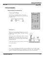
Depth of Cut
When you’re programming the depth of cut, you’ll be
prompted to provide the “Begin” and “End” locations
for the Z-axis.
The location that you enter into the “Begin” field tells
MILLPWR where you want the quill to begin cutting at
the programmed feed rate. The “End” location defines
the depth of the cut.
Always check that the “Begin” location is above the surface of the workpiece.
Pass
“Pass” refers to the number of cuts that are used to machine an area to its “End” depth.
You can control the number of passes by entering a value in the “Pass” field whenever it
appears. (If you don’t want to program more than one pass, leave the field blank.)
Operation Manual
3-1
PROGRAMMING
MILLPWR ®
Tool Offset
With MILLPWR, you never have to calculate the actual tool path. By using left
and right offsets, you can program the
dimensions of the part as identified on
your print.
When you program a line, arc, frame,
etc., use the “Tool Offset” field to tell
MILLPWR which side of the line you want
the tool to be on.
To determine which offset to use, picture yourself following the tool as it is moving. If the
tool needs to be on the left side of the line, use a "left" offset. If the tool needs to be on the
right side of the line, use a "right" offset.
If you use a "center" offset, the programmed dimensions are for the center of the tool.
For some milling functions, like frame and arc, "inside" and "outside" offsets are available
to make it easier for you to define your tool offset.
Datum Selection
Datum is where workpiece (absolute) zero is located. If
datum isn't defined on your print, then determine datum
based upon where most of your dimensions originate. You
should pick a point which will let you enter most of the
dimensions directly, with few (if any) calculations (refer to
Establishing Datum located in Section 2).
As you establish datum, you’ll be prompted to provide a
Z-retract position (the position the quill returns to between program steps). By setting a
retract position, you can ensure that the tool you are using does not make contact with your
workpiece when the quill moves from one position to the next. It’s a good idea to establish
a retract position for the Z-axis each time you power up your system; otherwise, MILLPWR
will use the quill’s upper travel limit as its default retract position (refer to Conventions
located in Section 1).
3-2
Operation Manual
PROGRAMMING
MILLPWR
®
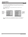
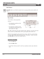
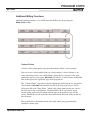
Absolute vs. Incremental Dimensions
allows you to enter both absolute and incremental dimensions. A dimension measured from the point you defined as datum is an absolute dimension. A dimension measured
from any other point is an incremental dimension.
MILLPWR
In the examples below, the print on the left shows datum located at the center of Hole
F—all dimensions are absolute. The print on the right shows datum located in the lower left
corner—point A. Most of these dimensions are incremental.
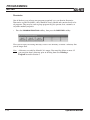
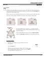
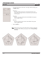
Continuous Milling
When you program a continuous contour of lines and/or
arcs, MILLPWR will cut the contour without stopping.
MILLPWR will automatically recognize continuous
contours as you're programming. There are no special
key presses or other functions to learn.
For lines and arcs to be continuous, they must:
•
•
•
•
•
Be consecutive steps in a program
Have the same depth
Be cut with the same tool
Be cut using the same tool offset
Share a common “From” or “To” point (one step must end at the point where another
begins)
Operation Manual
3-3
PROGRAMMING
MILLPWR ®
If one step follows another, MILLPWR assumes that you want them to be connected. It automatically fills in the “From” point, “Depth,” and “Tool Offset.” All you have to do is fill in
the “To” point and press USE.
Note: MILLPWR will allow you to program different feed rates within each step of a
continuous contour.
Single lines
indicate an
open-ended
continuous
tool path.
Double lines
indicate a
closed continuous tool
path.
Note: An “X” before or after a step number indicates that the step is invalid. Highlight the
step, press enter and correct the information as needed. Press use when finished.
3-4
Operation Manual
PROGRAMMING
MILLPWR
®
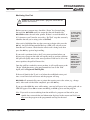
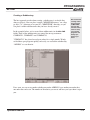
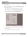
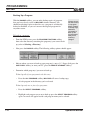
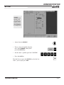
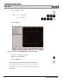
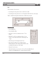
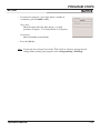
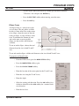
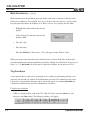
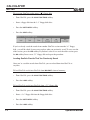
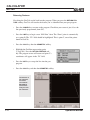
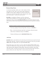
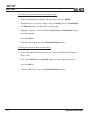
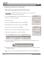
Creating a Program
•
Press the PGM key, and the following program screen will appear.
Programs are created by developing a list of milling steps to be performed. As you add
to your list, each step will immediately be drawn on the screen so that you can see a
graphic display of your part in progress.
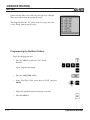
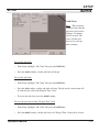
•
To enter a milling step, press the appropriate hard key milling function (such as Tool).
The milling function keys are the eight yellow keys located in the upper right corner of
your keypad. The function you select will appear in the program listing and will enable
you to enter the information describing the step into the program.
Program
steps are
added
here.
Operation Manual
Enter information
about a milling
function—such
as an arc—into
forms like this.
3-5
PROGRAMMING
MILLPWR ®
•
After entering all the data for a step, press the USE key to add the step to your program.
This immediately updates the part graphic and positions the cursor for the next step.
If you decide not to finish a milling function that you have begun, simply press the CANCEL
key.
•
To edit a step, use the arrow keys to highlight the step you want to change and press
USE or ENTER. When you have made your changes, press USE to accept your changes
and place the step back into your program.
•
To delete a step, highlight the step you want to delete, then press CLEAR.
•
To insert a step between the two existing steps, position the cursor to where you want the
new step to go, and press the desired milling function key.
In addition to the hard key milling functions, the MORE STEPS softkey lets you pick from a
number of other useful steps, such as CUSTOM POCKET, ISLAND, ELLIPSE, MIRROR, REPEAT
and ROTATE—each of which are described in the Program Steps section of this manual.
3-6
Operation Manual
PROGRAMMING
MILLPWR
®
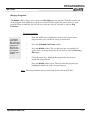
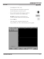
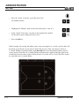
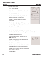
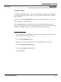
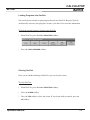
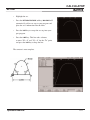
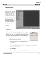
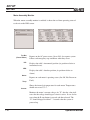
The View Key
If you need to see your part-graphic in more detail, press the VIEW key. This enables you to
access the following softkeys:
The FOLLOW TOOL, SHOW TOOL PATH and ZOOM functions may be used simultaneously.
Press the VIEW key (or the CANCEL key) at any time to return to the PGM screen.
FOLLOW TOOL
Press both the FOLLOW TOOL and ZOOM IN softkeys to see a close-up of the tool’s path.
MILLPWR will automatically adjust the part graphic so that the tool is always in view.
SHOW TOOL PATH
The SHOW TOOL PATH softkey shows the tool's cutting path as you run the program. With
this feature enabled, you can see where the tool has been.
ZOOM IN, ZOOM OUT and RESTORE
The ZOOM IN softkey will magnify the part graphic. The arrow keys will enable you to
adjust the view up, down, left and right. The ZOOM OUT softkey will de-magnify your part
graphic. RESTORE will return the part graphic to its original size.
Operation Manual
3-7
PROGRAMMING
MILLPWR ®
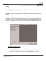
Running a Program
There are a few things you'll need to do before running a program, such as skewing the part
and establishing datum.
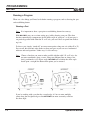
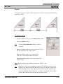
Skewing a Part
Note: It is important to skew a part prior to establishing datum for accuracy.
With MILLPWR, you can save time setting up a job by skewing your part. The skew
function automatically compensates for the offset angle of your part—so if your part is
not perfectly parallel with either the X- or Y-axis, you won’t have to spend time indicating it in.
To skew a part, simply “touch off” on two or more points along one axis (either X or Y).
You can use the electronic edge finder to skew your part or you can use a mechanical
indicator and teach position—either way, it’s fast and easy.
Note: Choose a line that you want to make parallel with the table’s X- or Y-axis—do
not enter coordinates along a curve, along two different lines or along a line
that’s positioned at a 45 degree angle. MILLPWR will calculate the skew angle
based upon a straight line between the points you’ve entered.
If you’re working with a part that has a rough edge, it’s best to enter multiple
points along the straightest edge so that MILLPWR can more accurately calculate
the skew angle.
3-8
Operation Manual
PROGRAMMING
MILLPWR
®
Using an electronic edge finder:
•
From the DRO screen, press the SKEW softkey.
•
Touch off on two or more points along any single straight edge of your part. You’ll
notice that the “Points” and “Angle” change as you enter points.
•
Press USE to accept all of the points and return to the DRO screen. Press CANCEL to
return to the DRO screen without accepting any points or affecting your previous
skew angle.
The CLEAR ANGLE softkey will reset the number of points and the skew angle to zero.
Using teach position:
•
From the DRO screen, press the SKEW softkey.
•
Move the table so that a mechanical indicator rests against any straight edge on the
part. Press the TEACH POSITION softkey to enter your coordinate.You’ll notice that the
“Points” change.
•
Now move the table so that the mechanical indicator touches another point on the same
straight edge. Press the TEACH POSITION softkey. You’ll notice that the “Points” and
“Angle” change.
Repeat this process for any additional points.
•
Press USE to accept all of the points and return to the DRO screen. Press CANCEL to
return to the previous screen without affecting your previous skew angle.
The CLEAR ANGLE softkey will reset the number of points and the angle to zero.
Operation Manual
3-9
PROGRAMMING
MILLPWR ®
Establishing Datum
Datum, also known as workpiece zero or absolute zero, is a point of reference that
MILLPWR bases all of your part's coordinates from.
You will need to establish datum for every job. Datum's location may be indicated on
your print; if it's not, then establish a datum that allows you to enter most of your part's
dimensions directly, with the least amount of calculations.
When establishing datum, you may find it easiest to locate a known point on each axis,
such as the edge of your part or a location on your vise or fixture.
Refer to the example below as a basic guide for establishing datum. You may decide to
"touch off" using an edge finder instead of a tool. Datum could be set at a point on
the top surface, a position beneath the surface, or at a point where there's no material
present (such as in the center of a circular part). The possibilities are endless—do what's
easiest for your particular job.
MILLPWR
will retain the datum you've set after your system has been powered down.
Note: When the “Datum” menu appears, you will also be asked to establish a Z-axis
retract position. The Z-axis retract position is the position that the quill returns to
between program steps (refer to Conventions located in Section 1).
To establish datum:
As we’ve already mentioned, where and how you establish datum will vary from job
to job. Here we’ll walk you through one of the most common methods of establishing
datum. Once you’ve learned the basics, apply the same principle when setting datum for
your own parts, making adjustments to the procedure as needed.
We’ll establish datum on the corner where the left, front and top surfaces of our part intersect. We’ll accomplish this by “touching” each face with the tool that we’re planning to
cut the part with.
Define datum one axis at a time. Here we’ll begin with the X-axis:
3-10
•
From the DRO screen, press the DATUM softkey.
•
Insert the tool you are planning to cut the part with into the spindle.
Operation Manual
PROGRAMMING
MILLPWR
®
•
Position the tool so that it is near, but not touching, the left side
of your part.
•
Lower the tip of the tool so that it falls below the top surface of
the part.
•
Move the table along the X-axis, slowly spinning the tool by
hand as you go. Pay close attention as the tool approaches the
part—you'll feel a subtle bump when they come into contact.
Stop the table at the moment the tool touches the part.
•
Using the keypad, enter the radius of the tool (the distance from the
center of the tool to the edge of your part) into the “X:” field. Be sure
to specify if it’s a negative value.
Use the MOVE
TABLE softkey
to help with
long table
moves.
Note: In our example, we'll need to specify a negative value, because the tool's center is on
the negative side of our datum (refer to Axis Conventions).
•
Press the ENTER key.
Now we'll set datum for the Y-axis using the same procedure:
•
Position the tool so that it is near, but not touching, the front face
of your part. The tip of the tool should fall below the top surface
of the part.
•
Move the table along the Y-axis, slowly spinning the tool by hand
as you go. Pay close attention as the tool approaches the part—
you'll feel a subtle bump when they make contact. Stop the table
at the moment the tool touches the part.
•
Using the keypad, enter the tool's radius into the"Y:" field (be sure to specify if it is a
negative value).
•
Press the ENTER key.
Operation Manual
3-11
PROGRAMMING
MILLPWR ®
Finally, we'll set datum for the Z-axis:
•
Position the tool so that its tip touches the top surface of your
part.
•
Using the keypad, enter "0" into the "Z:" field (or press the
Z = 0 softkey).
•
Press the ENTER key.
•
Highlight the “Z Retract” field.
•
Either:
Enter the Z-axis retract position (the position that you want the quill to return to
between steps—it must be located above the top surface of your part); OR
Raise the quill to the desired position, then press the TEACH softkey.
•
Press the USE key.
Datum and the Z-axis retract position have now been established.
You can quickly
move to datum
for X and Y by
pressing the
POS key. Check
that your go to
position is
0.0000 for both
X and Y, then
press the GO
key.
3-12
It's a good idea to test your datum setting before you begin programming. To
confirm that your new datum is correct:
•
Raise the tool and move the table
until both the X- and Y-axes dis
plays read "0.0000."
•
Lower the tool until it touches your part.
•
Check the tool's position—the lower left corner of the part should be
positioned directly beneath the center point of the tool.
•
Now check the readout screen. If the Z-axis says "0.0000," then your
datum is accurate and you can begin programming. If a value other
than 0.0000 appears in the Z-axis display, repeat the procedure for
establishing datum.
Operation Manual
PROGRAMMING
MILLPWR
®
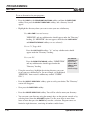
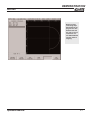
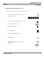
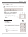
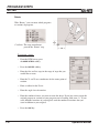
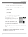
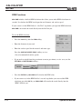
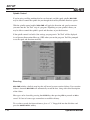
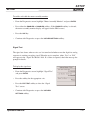
Testing Your MILLPWR Program
Whenever you are about to run a program, check that the
handles are recessed.
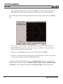
Before you machine a part, it is always a good idea for you to test your program for things like the
correct tool path, count direction, feed rate, and sequence of operations. MILLPWR provides several
run-time options to assist you. From the PGM screen, press RUN OPTIONS to display the following
softkeys:
Press any softkey to activate the option; press it again to deactivate it.
Note: Before you press the GO key to begin the “Single Step,” “Dry Run” or “Manual Positioning”
features, check that the tool will not touch the workpiece when the quill begins to move. To
avoid interference, we suggest that you do one or more of the following:
•
•
•
Lower the knee
Remove the tool or workpiece
Reestablish datum away from the part (refer to Establishing Datum)
SINGLE STEP
Normally, a continuous contour will be machined without stopping. With
“Single Step” activated, MILLPWR will stop after each step. This enables
you to check the position of the Z-axis relative to your part and ensure that
the tool path and other program details are correct. Press the GO key to
begin.
To test your
program quickly, press both
the DRY RUN
and GRAPHICS
ONLY softkeys.
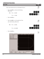
DRY RUN
With “Dry Run” activated, MILLPWR will run your entire program at high
speed without stopping. You can visually follow the position of the tool relative to your part and
ensure that the tool path and other program details are correct. The dry run speed is defined in
Setup. Press the GO key to begin.
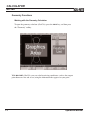
GRAPHICS ONLY
With this activated, the table and quill will not move. The graphics screen will show you how your
part will be cut. You can see all the normal feed rates, tool changes and so on. Press the GO key to
begin.
Note: Dry Run and Graphics Only can be used to quickly verify your program.
Operation Manual
3-13
PROGRAMMING
MILLPWR ®
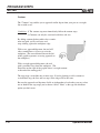
MANUAL POSITIONING
Use this option if you want to position the table using the handles. MILLPWR will operate
just like a programmable readout—each target position will be preset into the readout, and
you will be prompted to position the table manually. This feature is especially useful when
you’re navigating around islands. Press the GO key to begin.
DISABLE LOOK AHEAD
Normally, MILLPWR checks each step in a continuous tool path with other steps to determine
if there is an intersection in the tool's cutting path (such as in the number “8”). This is called
“look ahead.” If you press the DISABLE LOOK AHEAD softkey, your program will run without performing this function. Press the GO key to begin.
3-14
Operation Manual
PROGRAMMING
MILLPWR
®
Machining Your Part
Whenever you are about to run a program, check that the
handles are recessed.
Before you run a program step, check the “Status” bar (located along
the top of the MILLPWR screen) to ensure that the tool identified by
MILLPWR matches the tool in the spindle. If there’s no tool identified, or
if it’s incorrect, you’ll need to start with a “Set Tool” step that accurately
identifies the tool you’re using (refer to Set Tool).
To move quickly to a step, key
in its number
(look in the
message bar),
and press
ENTER.
After you’ve highlighted the step that you want to begin with, press the
GO key. An Operator Intervention Message (OIM) will ask you to confirm this tool is correct. Check that the correct tool is being used, then
press the GO key again to begin milling.
If your tool is positioned above the Z-axis retract position before you
begin to run a program, the table will rapidly move to position, and then
the quill will rapidly move to the retract position. If the tool is below the
retract position, the quill will move first.
Once the quill has reached its retract position, it will rapidly move to the
“Begin” depth then move at the programmed feed rate to the “End”
depth (refer to Begin and End Depths).
The remote
STOP/GO
switch acts as
PAUSE if the
table is moving
and as GO if
the machine is
paused or
stopped.
If the travel limit for the Z-axis is set below the established retract position, a travel limit fault will occur and the program will stop.
will automatically pause at points that require you to take action (e.g., change
tools). After each task has been completed, press the GO key.
MILLPWR
If you press the STOP key once while cutting, your tool will pause in its cutting path and an
OIM will appear. Press GO to resume machining, or STOP again to end the program.
Note: If you wish to start machining from the middle of a program and the tool in your
spindle does not match the tool information displayed in the current tool field, you
must start the program at the programmed tool step for that tool.
Operation Manual
3-15
PROGRAMMING
MILLPWR ®
Feed+ and FeedThe FEED+ and FEED- keys will change your feed rate by a certain percentage with each key
press. The feed rate percentage will be displayed in the status bar at the top of the screen. A
feed rate percentage of 100% means that actual feed rates will run at 100% of the programmed
feed rates. If the feed rate percentage is 50%, actual feed rates will run at half of the programmed feed rates.
You can press the FEED+ and FEED- keys at any time, even while the table or quill is moving.
Manually Positioning the Quill (Optional Linear Encoder Only)
Programs that do not include a “Begin” depth will require you to manually position the Zaxis during machining. The same is true when the Z-axis has been disengaged during setup
(refer to Setup).
If you have programmed an “End” depth, when it is time for you to manually position the
Z-axis, MILLPWR will preset the value into the readout's Z-axis display. The DRO screen
will appear, along with the prompts shown below.
is factory set in a “distance to go” display view. This way, any dimension you
have programmed will be "preset" into the readout display. Every move will end at zero.
MILLPWR
If you wish, you can setup MILLPWR to display incremental
travel (refer to Display Options in Section 7). In this view,
every move will end at the programmed depth.
This Operator Intervention Message will appear for optional
Z-axis Linear Encoder systems only:
3-16
Operation Manual
PROGRAMMING
MILLPWR
®
Program Functions
Accessing Load, Save, Delete, Merge, Backup and Directory Options
offers several versatile features for loading, saving, deleting, merging and backing
up your programs. You can also easily organize your programs by creating directories.
MILLPWR
To access these features, from the PGM screen, press the PROGRAM FUNCTIONS softkey.
You may load a program, save the program you’ve been working with, delete programs,
merge a saved program into your current one, create a backup copy, or select, create or
delete a directory.
Operation Manual
3-17
PROGRAMMING
MILLPWR ®
Directories
One of the best ways to keep your programs organized is to save them in directories.
Directories are like file folders—they should be clearly labeled and contain closely related programs. They may be used to group programs by job, operator, date, customer, or
any other method you prefer.
•
Press the PROGRAM FUNCTIONS softkey, then press the DIRECTORY softkey.
Now you can open an existing directory, create a new directory, or delete a directory that
you no longer need.
Note: A directory can only be deleted if it is empty. You must first delete or move all
part programs from a directory prior to deleting them. See Deleting a
Program located in Section 3.
3-18
Operation Manual
PROGRAMMING
MILLPWR
®
Creating a Subdirectory
The best approach to take when creating a subdirectory is to decide first
where to place it. You can place it on the "MILLPWR directory," on a floppy disk ("A:") directory or on your PC ("REMTSTOR") directory, or you
can place it within subdirectories that you have already created.
In the example below, we’ve created four subdirectories in the MILLPWR
folder. Three of the subdirectories are named for our top customers:
COMPANY1, COMPANY2 and COMPANY3.
We recommend
creating matching directories
on MILLPWR
and your PC.
This will make it
easier to keep
your original
programs and
backup programs organized.
"COMPANY1" has placed several part orders for a single month. To help
us find those part programs quickly and easily, we created the subdirectory
“APRIL99” to save them in.
If we want, we can create another subdirectory under APRIL99, layer another one under that,
one under that and so on. The number of directories you create and how you layer them is up to
you.
Operation Manual
3-19
PROGRAMMING
MILLPWR ®
To create directories for your programs:
•
Press the PGM key, the PROGRAM FUNCTIONS softkey and then the DIRECTORY
softkey. Now press the SELECT DIRECTORY softkey, and a directory list will
appear.
•
Highlight the directory where you want to store your new subdirectory.
Select MILLPWR's internal memory:
"MILLPWR" and any subdirectories should appear under the "Directory"
heading. (If “MILLPWR” does not appear, check that the USE FLOPPY
and REMOTE STORAGE softkeys are not selected.)
Select a 31/2" floppy disk:
Press the USE FLOPPY softkey. "A:" and any subdirectories should
appear under the "Directory" heading.
Select your PC:
Press the REMOTE STORAGE softkey. "REMTSTOR"
and any subdirectories should appear under the
"Directory" heading.
3-20
The REMOTE
STORAGE softkey will only
appear if MILLPWR has been
set up for
remote storage.
•
Using the arrow keys, highlight the existing directory you want
to put your new subdirectory in. (In our example, we highlighted
"MILLPWR," then created a subdirectory entitled "COMPANY1.")
•
Press the SELECT DIRECTORY softkey again to verify your choice. The "Directory"
screen will disappear.
•
Now press the DIRECTORY softkey.
•
Press the CREATE DIRECTORY softkey. You will be asked to name your directory.
•
You can name your directory using the numeric keys on the operator console or by
selecting letters from the ALPHABET option. Use the arrow keys to move from
letter to letter then press the ENTER key to make a selection. Program names are
limited to eight characters, consisting of numbers and/or letters.
Operation Manual
PROGRAMMING
MILLPWR
®
•
After you have named your directory, press the CREATE DIRECTORY softkey again
to enter your choice. The "Directory" screen will now disappear.
Additional directories may be added at any time.
IMPORTANT
Creating a directory does not mean that the directory is selected. If you plan
to save your current program in the directory you just created, you must select the
new directory first. Otherwise, your program will be saved in the last directory that
was selected.
Selecting a Directory
The SELECT DIRECTORY softkey allows you to open any of the directories that you’ve previously created on MILLPWR's internal memory, on a 31/2" floppy disk, or on your PC. You may
use this feature any time you save or load a program.
•
Press the PROGRAM FUNCTIONS softkey, then the DIRECTORY softkey. Press the
SELECT DIRECTORY softkey—a directory list will appear.
Operation Manual
3-21
PROGRAMMING
MILLPWR ®
•
Indicate where the directory you want to select is located.
On MILLPWR's internal memory:
“MILLPWR" and any subdirectories that you have created should appear under
the "DIRECTORY" heading.
On a 31/2" floppy disk:
Insert the 31/2" floppy disk containing the directory into the floppy disk drive
(located in the lower right-hand corner on the front of the operator console) and
press the USE FLOPPY softkey. "A:" and any subdirectories you have created
should appear under the "DIRECTORY" heading.
On your PC:
Press the REMOTE STORAGE softkey. "REMTSTOR" and any subdirectories you have created will appear under the "DIRECTORY"
heading.
The REMOTE
STORAGE softkey will only
appear if MILLPWR has been
set up for remote
storage.
•
Using the arrow keys, highlight the directory you want to open. (If
the list is long, use the PAGE UP and PAGE DOWN softkeys to scroll
through the list more quickly.)
•
Press the SELECT DIRECTORY softkey again. The "DIRECTORY" list will disappear,
indicating that your directory has been selected.
You can now save your program in the directory you have chosen; or if you prefer, load an
established program from the directory you selected (refer to Program Functions).
3-22
Operation Manual
PROGRAMMING
MILLPWR
®
Deleting a Directory
will not delete directories that contain programs. You must delete each program and
subdirectory stored within the directory first (refer to Deleting a Program).
MILLPWR
To delete a directory:
•
From the PGM screen, press the PROGRAM FUNCTIONS and DIRECTORY softkeys, then
press the DELETE DIRECTORY softkey.
•
Identify where the directory you want to delete is located.
On MILLPWR's internal memory:
"MILLPWR" and any subdirectories you have created should appear under the
"DIRECTORY" heading.
On a 31/2" floppy disk:
Insert the 31/2" floppy disk containing the directory into the disk drive (located in the
lower right-hand corner on the front of the operator console) and press the USE FLOPPY
softkey. "A:" and any subdirectories you have created will appear under the
"DIRECTORY" heading.
On your PC:
Press the REMOTE STORAGE softkey. "REMTSTOR" and any
subdirectories you have created will appear under the
"DIRECTORY" heading.
•
Using the arrow keys, highlight the directory you want to delete.
•
Press the ENTER key. Press the YES softkey to erase the directory
or the NO softkey to cancel.
Operation Manual
The REMOTE
STORAGE softkey will only
appear if MILLPWR has been
set up for remote
storage.
3-23
PROGRAMMING
MILLPWR ®
Saving a Program
You can save your programs in any of three places—on MILLPWR's internal memory, on a
31/2" floppy disk, or on your PC. It is always a good idea to save your programs often to
avoid losing valuable information.
•
From the PGM screen, press the PROGRAM FUNCTIONS softkey, then select the
directory where you want to save your program (refer to Selecting Directories).
•
Return to the PGM screen, then press the PROGRAM FUNCTIONS and SAVE softkeys.
You will be asked to name your program (refer to Naming a Program).
•
Press the SAVE softkey. The program's name should now appear in the left column
above the program steps.
If you make any changes, make sure that you save your program again.
3-24
Operation Manual
PROGRAMMING
MILLPWR
®
Naming a Program
Before you can save a program, MILLPWR requires you to name it.
•
If you want to use letters, press the ALPHABET softkey. An
alphabet menu will appear below the "Program Name"
field.
•
Using the arrow keys, move the cursor from one letter to
the next. Press the ENTER key to select a letter.
To add numbers to your program name, simply press any of the
number keys on the keypad.
You may choose up to eight characters for your program name,
mixing numbers and letters if you wish.
•
Press the SAVE softkey. MILLPWR will store your program in
the directory you have selected.
A message will alert you if the program was not saved properly, or if the
name that you’ve chosen already exists.
Operation Manual
If you have
accidentally
selected the
wrong letter or
number, press
the CLEAR key
and rename
your program.
3-25
PROGRAMMING
MILLPWR ®
Loading a MILLPWR (MPT) Program
The LOAD softkey allows you to open programs that have already been
saved. The steps below tell you how to load a program from MILLPWR's
internal memory, a 31/2" floppy disk, or your PC.
From MILLPWR's internal memory:
•
Save, then clear any open programs.
•
From the PGM screen, press the PROGRAM FUNCTIONS softkey,
then press the LOAD softkey. The last directory that was selected
and any programs it contains will appear.
If the program is saved in the MILLPWR directory:
3-26
•
"MILLPWR" should appear at the top. If it doesn't, check that the
USE FLOPPY and REMOTE STORAGE softkeys are not selected.
•
Press the format button until MPT is displayed.
•
Using the arrow keys, highlight the program you want to load, then
press the LOAD softkey. The program you've selected should appear
on your screen.
If you’re loading
a program that
was created on a
two-axes system, you will
have to add Zaxis information
before you run
the program.
If you don’t want
to add the Z-axis
information,
consider disabling the Z-axis
control and running in 2 axis
mode.
Refer to “Setup”
for further
instructions.
Operation Manual
PROGRAMMING
MILLPWR
®
If the program is saved in a different directory:
•
Press the CANCEL softkey.
•
Press PROGRAM FUNCTIONS softkey.
•
Press the DIRECTORY softkey.
•
Now press the SELECT DIRECTORY softkey.
•
Using the arrow keys, highlight the directory that contains the program you want to
load.
•
Press the SELECT DIRECTORY softkey again. The "DIRECTORY" screen will disappear. Now that you've selected the appropriate directory, you can load your program.
•
Press the LOAD softkey. The directory you chose should appear.
•
Highlight the program you want to load, then press the LOAD softkey. The program
you selected should now appear on your screen.
From a 31/2" floppy disk:
•
Save, then clear, any open programs.
•
From the PGM screen, press the PROGRAM FUNCTIONS softkey.
•
Insert the 31/2" floppy disk containing the file you want to load into the floppy disk
drive. Located in the lower right-hand corner of the operator console.
•
Press the DIRECTORY softkey and then press the SELECT DIRECTORY softkey.
•
Press the USE FLOPPY softkey. The “A:” directory and any sub-directories
should appear.
•
Select the directory that contains your program and then press the USE softkey.
•
Press the LOAD softkey.
•
Press the format key until MPT is displayed.
•
Using the arrow keys, highlight the program you want to load. Press the LOAD softkey. The program you selected should now appear on your screen.
Operation Manual
3-27
PROGRAMMING
MILLPWR ®
From your PC:
•
Save then clear, any open programs.
•
From the PGM screen, press the PROGRAM FUNCTION softkey, then press the
DIRECTORY softkey.
•
Press the SELECT DIRECTORY softkey.
•
Press the REMOTE STORAGE softkey. (If the REMOTE STORAGE softkey does not
appear, then it is likely the MILLPWR and your PC have not been set up. Refer to
Remote Storage and/or Installation Setup.) Select the directory you wish to use.
•
Press the USE softkey.
•
Press the LOAD softkey.
•
Press the FORMAT key until MPT is displayed.
•
Select the directory that contains your program (refer to Selecting a Directory).
Translating a DXF file:
•
Save, then clear, any running programs.
•
Locate the directory containing your DXF file (refer to Selecting a Directory).
•
From the PGM screen, press the PROGRAM FUNCTIONS softkey, then press the LOAD softkey.
•
Select the storage location of your DXF file.
(on a 31/2" floppy disk or on a PC):
If your DXF file is stored on a 31/2" floppy disk:
3-28
•
Insert the floppy disk containing the DXF file you want to load into the floppy
disk drive (located in the lower right-hand corner of the operator console).
•
Press the USE FLOPPY softkey.
•
Press the FORMAT softkey until DXF is displayed. The screen will display all of the
DXF files stored in the directory you’ve chosen.
•
Using the arrow keys, highlight the DXF file you want to translate.
Operation Manual
PROGRAMMING
MILLPWR
•
®
Press the LOAD softkey.
If your DXF file is stored on a PC:
•
Press the REMOTE STORAGE softkey. A “REMTSTOR” directory and any programs it
contains should appear.
If the REMOTE STORAGE softkey does not appear, then it is likely that MILLPWR and your PC
have not been set up properly (refer to Remote Storage and Installation Setup).
•
Press the format key until DXF is displayed. The screen will display all of the DXF files
stored in the directory you have chosen.
•
Using the arrow keys, highlight the DXF file you want to translate.
•
Press the LOAD softkey.
will read the DXF files you selected, then translate the file’s lines, points, arcs, and
circles into the appropriate MILLPWR milling function steps. Default values will be assigned for
any information that’s missing from the DXF file (such as tool offset, feed rate, etc.).
MILLPWR
will then arrange the steps in a logical order (based upon common end points) and
create a tool path. After the tool path has been determined, the program will appear on your
screen.
MILLPWR
We suggest that you test your program before machining to ensure that the program steps and
tool path do what you want them to do. You can easily edit and rearrange steps as needed (refer
to Step Functions).
Loading a G-Code file:
•
Save, then clear, any running programs.
•
From the PGM screen, press the PROGRAM FUNCTIONS softkey.
•
Select the directory containing your program (refer to Selecting a Directory).
•
Press the load softkey.
•
Press the format softkey until G-Code is displayed.
•
Using the arrows, highlight the program you wish to load
•
Press the LOAD softkey.
Operation Manual
3-29
PROGRAMMING
MILLPWR ®
If your G-code file is stored on a 3 1/2” floppy disk:
•
Insert the floppy disk containing the G-code file you want to load into the floppy disk
drive (located in the lower right-hand corner of the operator console).
•
Press the USE FLOPPY softkey.
•
Using the arrow keys, highlight the G-code file you wish to load.
•
Press the LOAD softkey.
If your G-code is stored on a PC:
•
Press the REMOTE STORAGE softkey. A "REMTSTOR" directory and any programs
it contains should appear.
If the REMOTE STORAGE softkey does not appear, then it is likely that MILLPWR and your PC
have not been setup properly (refer to Remote Storage and Installation Setup).
•
Select the directory containing your program (refer to Selecting a Directory).
•
Press the format key until G-code is displayed softkey. The screen will display all of the
G-codes files stored in the directory you’ve chosen.
•
Using the arrow keys, highlight the DXF files you wish to translate.
•
Press the LOAD softkey.
Note: G-code files are “run only.” No editing can be done to the file at the MILLPWR. All
editing should be done within your CAD/CAM program (refer to MILLPWR G-code
Conventions).
3-30
Operation Manual
PROGRAMMING
MILLPWR
®
Running a G-Code Program
Considerations when creating a G-code Program
MILLPWR has the ability to read and execute Numerical Code (G-Code) files, however those files can
not be edited from the controller. It is important to create and proof the G-code file before attempting
to machine a part.
The use of CAD/CAM Software is strongly recommended.
Tool Offsetting
No programmed cutter compensation is used so the tool path should be based on the center and tip of
the tool. Do not establish tool length offsets within CAD/CAM software. For repeatable tooling,
tool length offsets can be established in the tool library (Diameter offsets are not used).
Using the Tool Library
Each "T" block refers to the corresponding number in the Tool Library. For example, T1 will cause
MILLPWR to retrieve the tool length offset from tool 1 of the Tool Library. MILLPWR will then offset
the spindle by this amount. T2 will cause MILLPWR to retrieve the tool length offset from tool 2 of
the Tool Library, etc. To set up a Tool Library refer to Setup.
It is very important not to have any tool length offsets in the Tool Library
if the tooling is not repeatable.
Failure to maintain the Tool Library can cause unpredictable results. Verifying tool length offsets
prior to program execution is strongly recommended.
Loading a Program
A G-code program can be loaded into MILLPWR in the same manner as MILLPWR programs. (Refer
to Loading a Program for instructions on loading a G-code program.) With G-code files, there is no
accompanying graphics. Only the program list is displayed. Once loaded, MILLPWR will indicate
lines of code with invalid and unsupported blocks with an "X". If the line containing the code is highlighted, an error message also appears in the message line indicating that the line contains invalid
code. The invalid code can be removed by disabling the corresponding functions in the CAD/CAM
software and re-posting the G-code program. Simply removing the invalid code from the G-code program can cause unpredictable results and is not recommended.
Running a G-code Program
The tool path should be proofed prior to attempting to machine a part on MILLPWR.
Most CAD/CAM Software packages have this ability. When a program has been proofed and loaded
into MILLPWR, lower the knee and dry run the program to verify the tool path and speeds and feeds
are correct.
Operation Manual
3-31
PROGRAMMING
MILLPWR ®
Starting and Stopping a G-code Program
Always start the program from a place in the program where the feed rate, X-, Y-, and Zaxis position are known, such as a tool step. Alternate starting points can be programmed
by placing the proper code in the desired locations.
Pressing the GO button will cause MILLPWR to begin executing the current G-code program.
Always insure the program step highlighted is an appropriate starting point.
When a program is running, pressing the STOP button or the remote pendant will cause the
program and all axis motion to pause. Pressing the remote pendant switch again or the GO
button will cause the program to resume. Pressing the STOP button a second time will halt
the program execution.
3-32
Operation Manual
PROGRAMMING
MILLPWR
®
MILLPWR - G-Code Conventions
Table of G & M Codes
This table lists both the supported and unsupported codes. Non-supported codes are shown in gray.
Code
Description
Comment
D
Tool Diameter
MILLPWR does not support automatic cutter compensation.
Specifying a tool diameter index while cutter compensation is in
effect will generate a run-time error. Specifying a diameter index
while cutter compensation is off has no effect and is ignored.
F
Set Feed Rate
The feed rate uses the current program units in effect (ipm or
mmpm). The setting applies to current and subsequent blocks.
The default is determined from MILLPWR’s configuration
setup.
G0
G1
G2
G3
Linear Interpolation (Rapid)
Linear Interpolation (Feed)
Circular Interpolation (CW)
Circular Interpolation
(CCW)
These commands generate table/quill motion. The motion command applies to current and subsequent blocks containing at
least one X, Y, or Z coordinate. The default motion command is
a linear move at feed (G1).
G4
Dwell
G10
Offset Value Settings
This command causes the system to pause for a specified
period of time prior to any motion commands within the blocks.
The period of time is determined by the P value.
G10 is not supported.
G17
G18
G19
XY Plane Selection
XZ Plane Selection
YZ Plane Selection
These commands set the plane in which arcs are executed.
The setting applies to current and subsequent blocks. The
default is G17 (XY).
G20
G21
Set Program Units (Inch)
Set Program Units (MM)
These commands set the unit of measure. The setting applies
to current and subsequent blocks. The default is G20 (INCH).
G28
G30
Return to Home
Reference
MILLPWR does not have a method for establishing a “home”
position. If one or more coordinates are specified in the block,
the table/quill will rapidly move to that location. Program execution will continue with the next program block.
G40
Cancel Cutter
Compensation
Cutter Compensation (Left) MILLPWR does not support automatic cutter compensation.
Enabling compensation (G41 or G42) while a diameter (D is not
Cutter Compensation
equal
to 0) is in effect will generate a run-time error. Enabling
(Right)
G41
G42
compensation with no tool diameter specified (D = 0) has no
effect and is ignored.
Operation Manual
3-33
PROGRAMMING
MILLPWR ®
Code
G43
G44
G49
G54 to
G59
Description
Comment
MILLPWR does not support tool length offsetting. The offset is
Tool Length Offset (+)
retrieved from MILLPWR’s tool library when a tool change is exeTool Length Offset (-)
cuted. These commands are ignored.
Cancel Tool Length Offset
Work Coordinate System
MILLPWR does not support presettable work coordinate systems.
Selecting a coordinate system is possible, but setting it (G10 or
G92) will generate a run-time error.
G61
G64
These commands set the path mode. The setting applies to curSet “stop” Path Mode
Set “continuous” Path Mode rent and subsequent blocks. The default is G64 (continuous).
G80
Cancel Motion Mode
This command cancels the current motion command mode.
Motion is reset to G1. X, Y, and Z coordinates are reset to no
motion. I, J, and K coordinates are reset to no offset.
Canned Cycles
MILLPWR does not support canned drilling cycles (G81) through
G89).
G90
G91
Set Offset Mode (ABS)
Set Offset Mode (INC)
G92
G92 is not supported.
These commands set the mode for interpreting coordinates. In
ABS mode, coordinates are relative to MILLPWR’s datum. In INC
mode, coordinates are relative to the tool’s position after completing the previous move. The setting applies to current and subsequent blocks. The default is G90 (ABS).
G92 is not supported.
G94
Set feed/speed units (/sec) MILLPWR does not support “per revolution” units. G93 or G95 will
G81 tO
G89
generate a run-time error. G 93 & 95 are not supported.
All other G codes not listed will generate a run-time error.
G*
H
3-34
Tool Length Offset (Index)
MILLPWR does not support H-code tool length offsetting. The offset is retrieved from MILLPWR’s tool library when a tool change
is executed. This command has no effect and is ignored.
I
J
K
X Axis Offset to Arc Center
Y Axis Offset to Arc Center
Z Axis Offset to Arc Center
The offset applies to current and subsequent arc blocks (G2 and
G3). The default is offset.
N
Line Number
Line numbering is optional and for readability only. MILLPWR
does not make use of this information.
O
Program Number
Program number is optional. MILLPWR does not make use of
this information.
M0
Program Stop
M1
Optional Program Stop
This command stops the program after completion of the block.
The cursor moves to the subsequent program block. The current settings remain in effect.
This command is ignored. MILLPWR does not have a switch for
selecting whether to stop on this command.
Operation Manual
PROGRAMMING
MILLPWR
®
Code
Description
M2
Program End
This command stops the program after completing the block. The
cursor moves to the beginning of the program. The current settings
are reset to default values.
M3
M4
M5
Spindle On (CW)
Spindle On (CCW)
Spindle Off
If spindle control hardware is present, the spindle is turned on or off
automatically. If the hardware is not present, the operator is prompted to turn the spindle on or off and/or to set the speed.
M6
Tool Change
If the tool specified is not the current tool (tools do not match),
the operator is prompted to manually change the tool. MILLPWR
retrieves the tool length offset from the tool library. If the system
does not have repeatable tooling, the operator must establish the
Z-axis datum for the new tool before continuing.
M7
M8
M9
Coolant On (Mist)
Coolant On (Flood)
Coolant Off
If the AMI hardware is present, the coolant is turned on or off automatically. If the hardware is not present, the operator is prompted to
turn the coolant on (mist), on (flood), or off.
M30
Program End w / Pallet
Shuttle
MILLPWR does not support control of a pallet changer. This code
has the same effect as M2.
M48
M49
Enable Speed/Feed Override It is not possible to disable feed rate override on MILLPWR. These
Disable Speed/Feed Override commands are ignored.
M60
Program Stop w / Pallet
Shuttle
M*
Comment
MILLPWR does not support control of a pallet changer. This code
has the same effect as M0.
All other M codes not listed will generate a run-time error.
P
Dwell Time
The dwell time is specified in seconds. The setting applies to current and subsequent dwell blocks (G4). The default is 0.0 sec.
S
Spindle Speed
The spindle speed is set to the specified speed (rpm). If automatic
spindle control hardware is present, the spindle speed is set immediately. If not present or not enabled, the user is prompted to set
the speed. If the spindle is currently off (M5), it will not be turned on
unless accompanied by a spindle direction block (M3 or M4). The
setting applies to current and subsequent spindle direction blocks.
The default is 0 rpm.
T
Tool Selection
The tool selection represents the number of the tool to use at the
next tool change. The selection applies to current and subsequent
blocks containing a tool change (M6). The default is no tool selection.
X
Y
Z
X Axis Coordinate
Y Axis Coordinate
Z Axis Coordinate
The coordinates represent the destination for the G0, G1, G2, or
G3 command currently in effect. They use the current units (G20
and G21) and offset mode (G90 and G91).
Operation Manual
3-35
PROGRAMMING
MILLPWR ®
Additional G-code Conventions for MILLPWR
The following lists some of the expectations and limitations of programs imported into MILLPWR.
•
Blocks may contain multiple commands and are executed with the following precedence:
Messages
Tool Change
Spindle Control
Coolant Control
Dwell
Motion
Stop
•
•
•
•
•
•
•
•
•
Operator comments should be enclosed in parentheses.
An operator comment with “MSG” appearing within the text is considered a message. The
text following “MSG” (up to 22 characters) is displayed to the operator at run-time.
Program execution pauses until the operator acknowledges the message.
Arcs may only be programmed by endpoint and center. Using endpoint and radius will generate a run-time error.
Parametric programming (use of variables or algebraic operations) is not supported.
The characters (#, [,], <, or >) within a block will generate a run-time error.
Program delimiters (“%”) are ignored. Text following the delimiter is ignored.
Text following a programming comment character (“;”) is ignored.
White space is ignored between parameters but not within a numeric value or message.
If a coolant command (M7, M8 and M9) appears in the block, the Operator Intervention
Message is displayed regardless of the current coolant setting. If AMI hardware is present,
the block will execute without the need for any operator intervention or acknowledgement.
All tool diameter compensation must be made in CAD/CAM, however, the tool length off
set is read from MILLPWR’s tool library.
For example: In a G-code file, T1 will use the tool length offset from Tool #1 in the tool
library. T2 will use tool length offset from tool library tool #2, etc.
•
3-36
The skew feature does not work with G-code programs. Remove any skew angle prior to
running a G-code program.
Operation Manual
PROGRAMMING
MILLPWR
®
Merging Programs
The MERGE softkey allows you to merge two MILLPWR programs together. With this function, all
of the program steps within the program you selected will be copied into your current (or open)
program. Keep in mind that you can edit any of the new steps if you need to (refer to Step
Functions).
To merge programs:
It's always a
good idea to
save your work
before merging
programs so
that you can
easily recover
your original
program if you
need to.
•
From the PGM screen, highlight the step in your current (open)
program where you want the new steps to be inserted.
•
Press the PROGRAM FUNCTIONS softkey.
•
Press the MERGE softkey. The last directory that was opened will
appear. You can change directories if you need to (refer to Selecting a
Directory).
•
Using the arrow keys, highlight the program that you want to
merge into your program.
•
Press the MERGE softkey again. The steps from the program you
highlighted should now appear in your program.
Note: The merge function does not work with G-code files or DXF files.
Operation Manual
3-37
PROGRAMMING
MILLPWR ®
Backing Up a Program
With the BACKUP softkey, you can make backup copies of programs
that you have already saved on MILLPWR's internal memory. You
should keep backup copies on hand in case a program is accidentally
deleted or modified, or you can't recover the original programs for
any other reason.
To back up a program:
It's best to save
the final version
of a program
before creating
a backup copy.
Otherwise,
you'll have to
back up the
program again
after you've
made any
changes.
•
From the PGM screen, press the PROGRAM FUNCTIONS softkey,
then select the directory containing the program(s) you want to back
up (refer to Selecting a Directory).
•
Now press the BACKUP softkey. The following softkey options should appear:
•
Indicate where you want to back up your program(s): onto a 31/2" floppy disk (press the
USE FLOPPY softkey) or onto your PC (press the REMOTE STORAGE softkey).
•
Determine which program(s) you want to back up.
To back up all of your programs in the directory:
•
Press the ALL PROGRAMS softkey. MILLPWR will store a backup copy
of each program in the directory you've selected.
To back up only one or just a few programs:
3-38
•
Press the SELECT PROGRAMS softkey.
•
Highlight each program you want to back up press the SELECT PROGRAM softkey
again. An arrow will appear beside each program name you've selected.
Operation Manual
PROGRAMMING
MILLPWR
•
®
Now press the BACKUP PROGRAMS softkey. MILLPWR will highlight each program as
a backup copy is saved in the directory you've selected.
Note: If a program with the same name is already stored in the directory you've chosen,
MILLPWR will ask you if you want to replace the old copy with the latest copy. Choose
the YES softkey or YES TO ALL softkey to continue or the NO softkey to cancel.
Deleting a Program
You can delete any program that has been saved.
To delete a program:
•
Select the directory that contains the program you want to delete (refer to Selecting a
Directory).
•
From the PGM screen, press the PROGRAM FUNCTIONS softkey, then press the DELETE
softkey.
•
Using the arrow keys, highlight the program you want to delete.
•
Press the DELETE softkey. You will be asked if you are sure that you want to delete the program. Press the YES softkey to continue or the NO softkey to cancel.
IMPORTANT
By answering "Yes," you will erase the highlighted
program from memory. Deleted programs cannot be recovered
unless a backup file was previously created.
Operation Manual
3-39
PROGRAMMING
MILLPWR ®
This page intentionally left blank.
3-40
Operation Manual
DEMONSTRATION
MILLPWR
®
Demonstration Program
The following steps and key stroke sequences will guide you through creating a
demonstration program based upon information from the print below. This will help
introduce you to MILLPWR and familiarize you with how it operates.
Selecting Datum
Although there is no clear "zero point" identified on this print, use the center of the
bolthole pattern as datum. There are several advantages to
using this location:
•
it is the center of the bolt hole pattern
•
it is the center of the large arc, making it easy to calculate the arc's
start and end points
•
the pocket is dimensioned from this point
•
nearly all of the dimensions on the print originate from this point
This print could also be programmed using another point—the upper left corner, for
example—as datum.
The datum will be ready to set just before running a program.
Operation Manual
4-1
DEMONSTRATION
MILLPWR ®
Beginning The Program
Begin by pressing the PGM key.
Selecting A Tool
The logical first step for most programs is to choose the tool
that you want to begin with. Let's use a 1/4" FLAT END MILL.
4-2
•
Press the TOOL key.
•
Enter a value of 0.25
The tool length is optional— leave it blank.
•
Arrow down to TOOL TYPE.
•
Press the TOOL TYPES softkey.
•
Arrow down to FLAT END MILL and press the ENTER key.
Operation Manual
DEMONSTRATION
MILLPWR
®
Consider
entering a Tool
Position. This
will enable you
to go to a location away from
your workpiece
to change tools.
•
Arrow down to SPINDLE.
•
To use a forward spindle direction.
Press the FORWARD softkey then
press the ENTER key.
•
Set the cutter’s spindle speed for 1300 RPM.
•
Press the USE key.
You don't have to press the ENTER key after the last
value—you can just press USE.
Operation Manual
4-3
DEMONSTRATION
MILLPWR ®
Programming the Contour
This part can begin at several different places. Begin at the upper-left corner,
and cut in a clockwise (CW) direction.
•
Press the LINE key.
To enter a negative
number, use the
"±" key, not the "-"
or “+” key. The "-"
and “+” keys are
for performing
math operations
within a numeric
field.
•
Using the keypad, enter the following information:
FROM:
X1 = -3 ABS
Y1 = 1.5 ABS
TO:
X2 = 0 ABS
Y2 = 1.5 ABS
Z BEGIN DEPTH: .02 ABS
Z END DEPTH:
4-4
-.25 ABS
Operation Manual
DEMONSTRATION
MILLPWR
®
•
Now highlight the “Offset” field.
The tool specifications will be filled in automatically
from the information we entered in step 001.
•
To cut around the outside of the contour in a clockwise
direction, use a left offset. Press the LEFT softkey.
has been factory set with a feed rate of
10 inches per minute, which is fine for this operation.
MILLPWR
•
Press the USE key.
Notice that the line is immediately displayed on the
Program (PGM) screen. This is called immediate-part-view graphics.
Operation Manual
4-5
DEMONSTRATION
MILLPWR ®
Next program the arc:
•
Press the ARC key.
MILLPWR assumes
that you are continuing from where
you left off so it automatically fills in the “From” point,
the depth and tool information for you.
•
Enter the following information into the “To” and
“Radius” fields:
TO:
X2 = 0 ABS
Y2 = -1.5 ABS
RADIUS:
1.5 MINOR
Since this arc will be starting at the top and moving
around to the bottom, choose CW for the direction.
DIRECTION:
•
4-6
CW
Press the USE key.
Operation Manual
DEMONSTRATION
MILLPWR
®
Notice the lines
connecting steps
002 and 003 in the
program list. This
indicates that the
line and arc form a
continuous contour. MILLPWR will
cut them without
stopping.
Operation Manual
4-7
DEMONSTRATION
MILLPWR ®
Next, enter the line that starts at the bottom of the arc.
•
Press the LINE key and enter the following
information:
TO:
X2 = -3.0 ABS
Y2 = -1.5 ABS
•
Press the USE key.
•
Press the LINE key to add another line. Now
enter the following information:
TO:
X2 = -3.0 ABS
Y2 = -0.838 ABS
•
4-8
Press the USE key.
Operation Manual
DEMONSTRATION
MILLPWR
®
•
Press the LINE key.
•
Enter the following information:
TO:
•
X2 = .75 INC
Now press the ABS/INCR key.
assumes that you want to use the
X coordinate of the “From” point (X1) as your
incremental reference, which is exactly what
is needed.
MILLPWR
•
Press ENTER to confirm this and again to accept the
value.
•
Now enter the location of Y2 in the “To” field:
TO:
•
Y2 = 0 ABS
Press the USE key.
Operation Manual
4-9
DEMONSTRATION
MILLPWR ®
•
Press the LINE key again.
TO:
X2 = -3.000 ABS
Y2 = 0.838 ABS
•
Press the USE key.
Now go back and insert a BLEND between steps 006 and 007.
•
Using the UP arrow key, highlight
the last step, 007 Mill Line.
•
Press the BLEND key.
You can see in the program list that step 007 has moved
to step 008 and that the blend will be inserted into step 007.
Notice the “Steps” field is indicating that steps 6 and 8 will
be blended.
4-10
Operation Manual
DEMONSTRATION
MILLPWR
®
•
Enter a radius of 0.25 and press the USE key.
Notice how the last two lines are now "blended" together with a radius.
The BLEND step could just as easily have been inserted immediately after line 006.
In doing so, the BLEND step would show up in the listing, but it would not be
displayed graphically until the step that follows is added.
•
Press the down arrow key once to reach the end
of the program. Now more steps can be entered.
•
Press the LINE key.
TO:
X2 = -3.0 ABS
Y2 = 1.5 ABS
•
Press the USE key.
Operation Manual
4-11
DEMONSTRATION
MILLPWR ®
Notice how the lines next to the program steps have changed.
They now indicate that the contour is closed.
This happens when the “To” point of the last step is the same
as the “From” point of the first step.
Programming the Bolthole Pattern
Begin by changing the tool.
•
Press the TOOL key and enter 0.25" for the
diameter.
Again, skip the tool length.
4-12
•
Press the TOOL TYPE softkey.
•
In the “Tool Type” field, arrow down to “Drill” and press
ENTER.
•
Adjust the spindle direction and speed as needed.
•
Press the USE key.
Operation Manual
DEMONSTRATION
MILLPWR
•
®
Press the HOLES key and then press the BOLT CIRCLE softkey.
The following screen will appear:
Notice that the CENTER, DIRECTION and Z BEGIN are carried forward
from the arc that were programmed earlier. Enter the depth of cut, peck
radius and tool retract values.
•
Arrow down to the “Z End” field and enter a value of -0.4
•
Enter 6 in the “Peck” field.
•
Arrow down again and enter a radius of 0.75”
Operation Manual
4-13
DEMONSTRATION
MILLPWR ®
•
Press the “down” arrow key again, then enter 5 for
the number of holes.
•
Highlight the “Number” field in tool retract then enter a value of 3.
•
In the “Dwell” field, enter 5 seconds as the length of time needed
for the quill to pause during the retract cycle.
•
Press the USE key.
In this example, the starting and ending angles were not changed. As a result, your first hole will
be placed at zero degrees. If you were to look at the face of a clock, zero degrees will be at
3 o’clock. Without a specified ending angle MILLPWR will space the number of holes entered
evenly around a full circle. If a counter-clockwise direction was applied to the hole pattern, the
second hole of our five hole pattern will be between 12 o’clock and 1 o’clock. The holes continue around the circle as shown below.
4-14
Operation Manual
DEMONSTRATION
MILLPWR
®
Programming the Rectangular Pocket
First, let’s enter the tool that is needed to machine the pocket.
•
Press the TOOL key and enter the data for a 0.125"
diameter flat end mill.
•
Arrow down and highlight the “Tool Type” field.
•
Press the TOOL TYPE softkey.
•
Highlight “Flat End Mill.”
•
Press the ENTER key.
•
Adjust the spindle direction and speed.
•
Press the USE key.
•
Press the RECT (rectangle) key, then press the
POCKET softkey.
Operation Manual
4-15
DEMONSTRATION
MILLPWR ®
The “Rectangle Pocket” screen will
appear:
•
Enter the following information:
1ST CORNER: X = -2.0 ABS
Y = -1.0 ABS
SIZE:
0.5 ABS in X
2.0 ABS in Y
•
Arrow down and highlight the “Pass” field.
•
Enter 2 for the number of passes.
•
Arrow down and enter the following information:
DIRECTION:
•
CCW
Arrow down and enter the following information:
CORNER BLEND RADIUS:
•
4-16
0.125
Press the USE key.
Operation Manual
DEMONSTRATION
MILLPWR
®
Saving Your Program
Your demonstration part program is now complete.
•
To save your program, press the PROGRAM FUNCTIONS softkey.
•
Press the SAVE softkey.
•
You can name your program by pressing the numeric keys
or by pressing the ALPHABET softkey, highlighting a letter,
and then pressing the ENTER key. You may select up to
eight characters, mixing numbers and letters if you wish.
•
After you've named your program, press the SAVE softkey to
save it.
You will be warned if a program already exists with the
name that you have entered.
Saving the program means that it is stored and will not be
lost if there is a power interruption.
You can retrieve the program later by pressing
the PROGRAM FUNCTIONS and LOAD softkeys.
Operation Manual
4-17
DEMONSTRATION
MILLPWR ®
Testing Your Program
It’s always a good idea to test your program before you cut
your part.
Dry Run with Graphics Only
•
Press RUN OPTIONS and then select both the DRY RUN and
GRAPHICS ONLY softkeys.
•
Press RUN OPTIONS again to finish.
•
Move to the start of the program by pressing the 1 key
followed by the ENTER key.
•
Now press the GO key. Watch as MILLPWR shows you how
the part will be cut at dry run speed.
Dry Run with Movement
•
Press RUN OPTIONS. Press GRAPHICS ONLY to
de-select it.
Before you press the GO key to begin the dry run, ensure
that the tool will not touch the workpiece when the quill
begins to move. To avoid tool interference, we suggest
that you do one or more of the following:
• Lower the knee
• Remove the tool or workpiece
• Reestablish datum away from the part (refer to
Establishing Datum located in Section 2).
4-18
Operation Manual
DEMONSTRATION
MILLPWR
®
If your cursor
is positioned
past the last
step, MILLPWR
will automatically go to step
001 when you
press GO.
•
Now press the GO key and check that the Z-axis
is engaged.
•
Press the GO key again. MILLPWR will run each
step at dry run speed without stopping.
If the part falls entirely within the workpiece, you can
cut the part.
Running the Program
The first step in running a new program is to establish datum.
Remember to chose the center of the bolt circle as datum.
•
Place your workpiece into a vise.
•
Place the tool you want to use first into the spindle.
•
Using the MOVE TABLE softkey and the arrows, position the
tool over the workpiece where you want the center of the bolt
circle’s datum to be.
•
After you’ve finished moving the table, press the MOVE
TABLE softkey again to de-select it.
•
Touch the tool to the top surface of your workpiece.
•
From the DRO screen, press the DATUM softkey.
•
Press the X = 0, Y = 0 and Z =0 softkeys to establish
the current tool position as datum.
•
Press the ARROW DOWN softkey.
•
Set the Z retract position 1” above the workpiece.
•
Press the USE key.
•
Return to your program by pressing the PGM key. Perform a
second dry run, this time allowing the table to move, to see if there is
enough material to run the program. Set zero.
Operation Manual
4-19
DEMONSTRATION
MILLPWR ®
Tool Changes
Whenever you encounter a SET TOOL step, MILLPWR will display the DRO screen and let
you know which tool to load. If no tool diameter was programmed in the “Tool Step,” you
will be prompted to provide one.
•
Use the MOVE TABLE softkey and arrow keys to move the tool
away from your workpiece.
•
Insert the required tool into the spindle.
•
Using the MOVE TABLE feature, position the tool over
the surface of a known depth on your workpiece.
•
Press the DATUM softkey.
•
Position your tool so that it touches a known surface,
then enter that position into the Z-axis.
•
Press the USE key.
•
Raise the tool and press the GO key to continue the program.
If the surface is
at datum 0, use
the Z = 0 softkey.
Clearing the Program
4-20
•
From the PGM screen, press the CLEAR softkey.
•
Press the YES softkey. The PGM screen will be cleared and ready
for another program.
Operation Manual
PROGRAM STEPS
MILLPWR
®
Simple Milling & Drilling
Most of the program steps described in this section can be performed as one-step
milling functions from the DRO screen or included as steps in a program (press the PGM
key).
Set Tool
"Set Tool" defines your tool and should appear as the first step in all of your
programs. You should also insert a "Set Tool" step anywhere you want to change
tools. MILLPWR will apply your latest tool setting to the program steps that follow.
To program a “Set Tool” step:
• Press the TOOL key.
• Enter the tool's diameter.
Note: If you leave the “Diam” field blank, you
will be prompted to provide a diameter
once the program is running.
Consider
entering a
Position/Drill
step before the
Set Tool step.
This will enable
you to go to a
location away
from your workpiece to change
tools.
Note: Tool length offsets are mentioned later on
within this section.
• Highlight the "Tool Type" field.
• Press the TOOL TYPES softkey for a list of
available tool types.
• Highlight a tool type, then press the ENTER key.
• For spindle control, select from the OFF, FORWARD and REVERSE softkeys.
If you press the
TOOL LIBRARY
softkey, highlight a tool and
press ENTER,
MILLPWR will
fill in the
"Diam,"
"Length" and
"Tool Type"
fields for you.
If you selected "Forward" or “Reverse,” enter a spindle speed. An Operator
Intervention Message (OIM) will prompt you to set the speed and direction
when you run your program. (If your machine's set up to control the spindle,
MILLPWR will adjust the speed and direction for you.)
• Tool Position allows the operator to enter a position to which the tool will
move so you can perform a tool change while running a program.
• Required Change is used if the operator, for any reason, wants to move the
tool into position for a tool change even if there is no tool change actually
required. Pressing YES for “Required Change” field will activate this prompt.
•
Operation Manual
Press the USE key.
5-1
PROGRAM STEPS
MILLPWR ®
Programming a Tool Step with Repeatable Tool Length Offsets
See the graphic below to identify the tools you will be using.
If you begin setting the tool length offsets by setting Datum using an electronic edge finder it
must have a fixed and repeatable length. The current tool information cannot have a length value.
All of the tool length offsets in the program will be the difference in length between the tool and
the edge finder.
When defining tool length offsets in the Tool Step, touch each tool to the same surface and press
the TEACH TOOL LENGTH softkey to establish the tool length.
Once you have identified the tools you will be using, you can program the length offsets into the
tool steps.
Entering the first tool
Set your Z-axis Datum with a tool or standard using no tool length offset. In our example, we use
the first tool in the program to set datum zero. If you wish to use a 3-D electronic edge finder or
tool holder with a repeatable standard, then place it into the spindle instead, and set datum.
Then you find the tool length offset for tool 1 as well.
5-2
Operation Manual
PROGRAM STEPS
MILLPWR
•
•
•
•
•
•
•
•
•
®
From the DRO screen, press the TOOL key.
Enter the diameter and then enter zero for the tool length.
Press GO.
An Operator intervention message will appear asking you to “use” the entered tool.
Place your first tool in the spindle and press GO again.
MILLPWR is now set with a zero tool length offset.
Press the DATUM softkey.
Touch the current tool to the top of the workpiece.
Press the “Z=0” softkey, then the USE key.
Use this same location to “teach” each tool length in the program.
•
•
•
•
•
•
•
•
•
•
•
•
•
•
Press the PROGRAM key and highlight the first tool step.
Press ENTER.
Use the numeric keypad to enter the tool’s diameter.
Highlight the length field and insure the length offset is zero. (If you used a 3-D electronic
edge finder or tool holder with a repeatable standard to set datum, then touch tool 1 to the same surface
you used to set the Z-axis datum above and teach its tool length here.)
Highlight the next tool step and press ENTER.
Use the numeric keypad to enter the tool’s diameter.
Place this tool into the spindle and touch its tip to the same surface you used to set the
Z-axis datum Zero above.
Press the TEACH TOOL LENGTH softkey. The length offset for this tool will appear in the
length field.
Highlight the “unit” field. If the diameter you entered is metric, press the MM softkey.
Highlight the “Type” field.
Press the TOOL TYPES softkey.
Highlight the type of your tool from the list of available tool types and press ENTER.
Press USE, and repeat this procedure for each additional tool in the program.
If your Z-axis datum is not located at the top of your workpiece, you will need to reset
your Z-axis datum. Be sure to set your Z-axis datum using the tool shown in the “current
tool” box located in the status bar on the top of the screen. If the tool doesn’t match,
the datum will not be correct.
After the tool information is established in the program, later you can edit the values as needed to
adjust for accuracy and wear.
Operation Manual
5-3
PROGRAM STEPS
MILLPWR ®
Changing to a Tool of unknown length when in the DRO
If you are using the DRO and need to set a new tool, follow the procedure below. Be sure to reestablish the tool length offset for your program before running it as described below.
•
•
•
•
•
•
•
From the DRO view, press the TOOL key.
Enter the tool diameter, clear any length and if you wish, the type.
Press the GO key.
An Operator intervention message will appear asking you to “use” the selected tool.
Place the selected tool in the spindle.
Press the GO key to confirm that you have installed the tool.
Set the Z-axis datum following the instructions found in your operation manual.
At this point, your program’s tool length offsets are no longer valid. Follow the steps below to
reestablish the Z-axis datum and tool length offsets for your program.
•
•
•
•
•
•
From the PROGRAM view, highlight any tool step.
Press the GO key.
An Operator intervention message will appear asking you to “use” the programmed tool.
Place this tool in the spindle.
Press the DATUM softkey.
Reset the Z-axis datum following the instructions found in your operation manual.
By resetting Datum during a tool step within the program, all of the tool offsets in the
program become valid again.
Changing to a Tool of unknown length in program
When running a program, it is easy to switch between tools of known length, to tools that have a
non-repeatable length such as a counter-bore held in an R-8 collet. For example, let’s say a program
is being run that has tool 1 -a center drill- in a repeatable holder, as the first step.
Step 2 in the program is a bolthole pattern.
Step 3 is a tool step using tool two-a drill- in a chuck that also repeats.
Step 4 is the same hole pattern repeated.
Step 5 is a tool step programmed as a counter bore of unknown length.
Step 6 is the same hole pattern repeated.
For this example, if two identical parts are being machined. The first part is in place and datum has
been set using tool one from the program as the current tool.
5-4
Operation Manual
PROGRAM STEPS
MILLPWR
®
The top of the workpiece is Z-zero. When the GO button is pressed, MILLPWR will see that step
one is asking for the same tool as the current tool and will proceed on the next step. When the
next tool step is executed, you will be prompted to change tools to the drill. Simply change the
tool and press GO to continue. The next tool-step 5- is of unknown length. When this step is
executed, and you are prompted to change tools,
•
•
•
•
Press the DATUM softkey. The DRO screen will appear with the set datum window.
Place the counter bore in the spindle and touch the cutting edge to the top of the
workpiece.
Press the Z=0 softkey and then ENTER. The tip of the tool is now set at datum zero.
Press GO to continue with the program.
Since the Z-axis datum was set using a tool of unknown length, the programmed tool lengths
will not repeat until the Z-axis datum is reset again, using a tool of known length. This can be
done when step 1 is run on the second part. After the part has been changed,
•
•
•
•
•
Press GO. You will be prompted to change tools to the center drill.
Press the DATUM softkey. The DRO screen will appear with the set datum window.
Place the center drill in the spindle and touch the tip to the top of the workpiece.
Press the Z=0 softkey and then ENTER. The tip of this tool is now set at datum
zero.
Press GO to continue with the program.
Now that datum has been reset with a tool of known length, all of the preset tools again relate
to datum. The program can continue as usual.
Operation Manual
5-5
PROGRAM STEPS
MILLPWR ®
Position/Drill
The position/drill function will move your table to the position
you want based upon your X- and Y-axes coordinates.
To program a position/drill step:
•
Press the POS key.
•
Enter the X- and Y-axes coordinates.
•
Enter the begin and end depths for the Z-axis.
•
(Optional) Enter either the number of pecks OR the distance
between each peck.
•
Select the DRILL, BORE or POSITION softkey.
•
Enter the Z-axis feed rate.
•
If you want the tool to retract:
Enter either the number of retracts OR the distance between each
retract.
Enter the length of time (in seconds) the quill should dwell (pause)
during the retract cycle.
Drill - The quill
will feed down
then rapidly move
up.
Bore - The quill
will feed down
then feed up.
Position - You will
be prompted to
move the quill
manually.
Enter the lenght of time (in seconds) the tool should dwell at the end
depth before the final retract.
•
Press the USE key.
Note: If the tool size and type listed in the "Tool" field are incorrect, change the tool
settings before running your program (refer to Programming a Tool Step).
5-6
Operation Manual
PROGRAM STEPS
MILLPWR
®
Center Line
With the position/drill feature, you can also locate the midpoint of two points or the
center line of a circle.
To locate a center line:
•
Press the CENTER LINE softkey.
•
Locate the first edge then press the ENTER key.
•
Locate the second edge of your part then press the ENTER key.
•
If you're calculating the center of a circle, locate then enter three
points along the diameter of the circle.
•
Press the USE key.
Operation Manual
If you use an
electronic edge
finder, the points
will automatically
be entered on
contact—even if
you over-travel.
5-7
PROGRAM STEPS
MILLPWR ®
Line
Lines are defined by their “From” point (the point where they begin) and “To” point (the
point where they end).
There are two ways you can program a line:
•
With four coordinates (X1, Y1, X2, Y2)
•
With three of the coordinates above (X1, X2, Y2 or X1,
Y1, X2, etc.) and an angle
Choose a method based upon the information available from your print.
To program a line:
•
Press the LINE key.
•
Enter the beginning X- and/or Y-axes coordinates into the
“From” field.
•
Enter the ending X- and/or Y-axes coordinates into the “To”
field.
•
Enter the begin and end depths for the Z-axis.
•
Enter the Z-axis feed rate.
•
If one of the X- or Y-axes fields above was left blank, enter an
angle.
•
Highlight the "Offset" field and press the LEFT, CENTER, or
softkey.
RIGHT
•
Enter the table’s feed rate.
•
Press the USE key.
Note: If the tool size and type listed in the "Tool" field are incorrect, change the tool
settings before running your program (refer to Programming a Tool Step).
5-8
Operation Manual
PROGRAM STEPS
MILLPWR
®
Arc
An arc can be defined several ways:
•
With a From point, To point and a radius
•
With a From point, To point and a center point
•
With a From, To and a 3rd point along the arc
•
With a From or To point, center point and a
sweep angle
Choose a method based upon the information available from your print. While programming,
keep in mind that the arc's sweep angle is measured from the X-axis.
To program an arc:
•
Press the ARC key.
•
Enter the beginning coordinates for the X-axis (X1) and Yaxis (Y1) in the “From” field.
•
Enter the ending coordinates for the X-axis (X2) and Y-axis
(Y2) in the “To” field.
•
Enter the begin and end depths for the Z-axis.
•
Enter the Z-axis feed rate.
•
Enter the arc's radius, then press either the MAJOR ARC or
MINOR ARC softkey. (A major arc has a sweep angle greater
than 180 degrees; a minor arc’s sweep angle is less than 180
degrees.)
MAJOR
ARC
Operation Manual
MINOR
ARC
5-9
PROGRAM STEPS
MILLPWR ®
•
Select the cutting direction. Press the CW softkey for a clockwise direction or the CCW
softkey for a counter-clockwise direction.
•
Arrow down and highlight the "Offset" field. Using the softkeys, select the tool offset—
LEFT, CENTER, RIGHT, INSIDE or OUTSIDE.
•
Enter the table’s feed rate.
•
If you need to enter a center coordinate, 3RD point and/or sweep
angle:
Center
Enter the center coordinate’s position for the X- and
Y-axes.
3RD Point
Enter your 3RD coordinate’s position for the X-axis (X3) and
Y-axis (Y3).
Sweep Angle
Enter the sweep angle.
Information that appears in blue has been calculated. If any of these values are already
displayed in blue, then MILLPWR has enough data for the arc and has calculated the rest.
•
Press the USE key.
Note: If the tool size and type listed in the "Tool" field are incorrect, change the tool
settings before running your program (refer to Programming a Tool Step).
5-10
Operation Manual
PROGRAM STEPS
MILLPWR
®
Blend
A blend is an arc that connects two lines, two arcs or a line and an arc. All you have to do is
provide the radius for the blend and indicate whether it is normal or inverted. MILLPWR will
calculate the tangent points for you.
The two steps you want to blend can, but don't have to, intersect or touch. If they don't come
into contact with each other, check that your radius is large enough to connect them.
It's also possible to close a contour (e.g., a triangle) using the
blend feature by inserting a blend step immediately after the last
step in the contour.
After you enter the blend's radius, press the CLOSE CONTOUR
softkey, and MILLPWR will blend the last step with the first step.
To program a blend:
•
Highlight a step within your program where you want to
place a blend.
•
Press the BLEND key.
•
Check that the steps listed in the “From” and “To” fields are the
steps you want to blend. (If they're incorrect, press the CANCEL
key and highlight the appropriate step.)
Operation Manual
5-11
PROGRAM STEPS
MILLPWR ®
5-12
•
Enter the blend's radius. (Press the CLOSE CONTOUR softkey
if you want to blend the end of a contour with the beginning.
The step numbers in the “To” and “From” fields will automatically change.)
•
Press either the NORMAL ARC or INVERTED ARC softkey. A
normal arc curves outward; an inverted arc curves inward.
•
Enter the table’s feed rate.
•
Press the USE key.
Operation Manual
PROGRAM STEPS
MILLPWR
®
Rectangular Milling Functions
MILLPWR offers several rectangular milling functions that let you program pockets,
frames, faces and slots quickly and easily.
Pocket
A pocket is a cavity or area on your part where material
is removed when you machine. You can program a rectangular pocket two ways:
•
Using the coordinates of two diagonal corners.
•
Using the coordinates of one corner and the size of
the pocket.
To program a rectangular pocket:
•
Press the RECT key.
•
Press the POCKET softkey.
•
Enter the X- and Y-axes coordinates for the pocket's 1ST Corner.
•
Now enter either the size of the pocket or the coordinates for the
2ND Corner.
Size
Enter the length of the pocket along the X- and Y-axes.
2ND Corner
Enter the X- and Y-axes coordinates for the 2ND Corner.
(The 2ND Corner must be located diagonally from the 1ST
Corner.)
Operation Manual
5-13
PROGRAM STEPS
MILLPWR ®
•
Enter the begin and end depths for the Z-axis.
•
Enter either the number of passes OR the distance
between each pass. “Pass” refers to the cuts that
are used to machine the pocket to its “End” depth.
•
Enter the Z-axis feed rate.
•
For “Direction,” press either the CW softkey for a clockwise cutting direction or the
CCW softkey for a counter-clockwise cutting direction.
•
Arrow down and enter the table’s feed rate.
•
The corner
blend radius
defaults to the
last radius
entered. Check
the value to
ensure that it is
correct.
If you need to program a corner blend
radius, tilt angle and/or finish cut:
Corner Blend Radius
You can add a corner blend radius to the
corners of a rectangular pocket.
Highlight the “Corner Blend Radius” field
and enter a radius.
Tilt Angle
You can tilt a rectangular pocket by identifying a tilt angle.
Highlight the “Tilt Angle” field and enter an
angle (measured from the X-axis).
Finish
Finish allows you to leave some excess material that will be removed
during the finish cut reducing, if not eliminating tool marks. The finish cut will automatically arc on and arc off.
Enter the amount of material to be removed during the finish cut.
Enter the feed rate for the finish cut.
5-14
Operation Manual
PROGRAM STEPS
MILLPWR
®
Select the finish cut’s direction. Press the CW softkey for a clockwise direction or
the CCW softkey for a counter-clockwise direction.
Enter a stepover percentage (how much you want your tool to overlap on each pass).
•
Press the USE key.
Note: If the tool size and type listed in the "Tool" field are incorrect, change the tool settings before running your program (refer to Programming a Tool Step).
Operation Manual
5-15
PROGRAM STEPS
MILLPWR ®
Frame
When you program a rectangular frame, you define it by its first corner, and its size
or diagonal corner.
To program a rectangular frame:
5-16
•
Press the RECT key.
•
Press the FRAME softkey.
•
Enter the X- and Y-axes coordinates for the frame's 1ST
Corner.
•
In the “Size” field, enter the length of the frame along the
X- and Y-axes (unless you’re programming a 2ND Corner).
•
Enter the begin and end depths for the Z-axis.
•
Enter either the number of passes OR the distance
between each pass. “Pass” refers to the cuts that are used
to machine the pocket to its “End” depth.
•
Enter the Z-axis feed rate.
•
(Optional) Enter a corner blend radius.
Operation Manual
PROGRAM STEPS
MILLPWR
®
•
For “Direction,” press either the CW softkey for clockwise or the CCW softkey for a
counter-clockwise direction.
•
Arrow down and select a tool offset by pressing the appropriate
softkey.
•
Enter the table’s feed rate.
•
If you need to program a 2ND Corner, tilt angle and/or finish
cut:
2ND Corner
Enter the X- and Y-axes coordinates for the 2ND Corner.
(The 2ND Corner must be located diagonally across from the
1ST Corner.)
Tilt Angle
Enter the tilt angle.
Finish
Highlight "Cut" in the“Finish” field. Enter the amount of material to be removed
during the finish cut.
Enter the feed rate for the finish cut.
For “Direction,” press either the CW softkey for clockwise or the CCW softkey for a
counter-clockwise direction.
•
Press the USE key.
Note: If the tool size and type listed in the "Tool" field are incorrect, change the tool
settings before running your program (refer to Programming a Tool Step).
Operation Manual
5-17
PROGRAM STEPS
MILLPWR ®
Face
The “Rectangle Face” step provides a quick way to face off your workpiece.
Simply enter the coordinates from one corner and either the size of the area to be
faced off or the coordinates for a diagonal corner. MILLPWR will position your table
at the lower left end of the area you've programmed.
To program a rectangle face:
5-18
•
Press the RECT key.
•
Press the FACE softkey.
•
Enter the X- and Y-axes coordinates for the face's 1ST
Corner.
•
In the “Size” field, enter the length of the face along the
X- and Y-axes (unless you’re programming a 2ND Corner).
•
Enter the begin and end depths for the Z-axis.
•
Enter either the number of passes OR the distance between
each pass. “Pass” refers to the cuts that are used to machine
the pocket to its “End” depth.
Operation Manual
PROGRAM STEPS
MILLPWR
®
•
Enter the Z-axis feed rate.
•
Select a tool offset by pressing the appropriate softkey.
•
Enter the table’s feed rate.
•
If you wish to program a 2ND Corner and/or a tilt angle or
would like to program a finish cut, press the MORE softkey.
2ND Corner
Enter the X- and Y-axes coordinates for the 2ND Corner.
(The 2ND Corner must be located diagonally across from
the 1ST Corner.)
Tilt Angle
Enter the tilt angle.
Finish
Enter a stepover percentage (how much you want your tool to overlap on each
pass).
•
Press the USE key.
Note: If the tool size and type listed in the "Tool" field are incorrect, change the tool
settings before running your program (refer to Programming a Tool Step).
Operation Manual
5-19
PROGRAM STEPS
MILLPWR ®
Slot
You can program a slot two ways:
•
By entering the center point of each arc and the slot's width
•
By entering the center point of one arc, the length and width of the slot, and an angle
Choose a method based upon the information available from your print.
To program a slot:
5-20
•
Press the RECT key.
•
Press the SLOT softkey.
•
Enter the X- and Y-axes coordinates for the “1ST Arc
Center.”
•
Enter the X- and Y-axes coordinates for the “2ND Arc
Center” or arrow down and enter the “Slot Length” and
“Angle.”
•
Enter the begin and end depths for the Z-axis.
•
Enter either the number of passes OR the distance
between each pass. “Pass” refers to the cuts that are used
to machine the pocket to its “End” depth.
•
Enter the Z-axis feed rate.
•
Select the direction you want your arc to be cut. Press the CW softkey for
clockwise or the CCW softkey for a counter-clockwise direction.
Operation Manual
PROGRAM STEPS
MILLPWR
®
•
Enter the slot's width.
•
Enter the slot’s length.
•
Arrow down and enter the feed rate.
•
If you want to program a tilt angle and/or finish cut:
Tilt Angle
You can slant a slot by identifying a tilt angle.
Highlight the “Tilt Angle” field and enter an angle
(measured from the X-axis).
Finish
Enter the amount of material to be during the finish
cut.
Enter the feed rate for the finish cut.
Select the finish cut’s direction. Press the CW softkey for a clockwise direction or
the CCW softkey for a counter-clockwise direction.
Enter a stepover percentage (how much you want your tool to overlap on each pass).
•
Press the USE key.
Note: If the tool size and type listed in the "Tool" field are incorrect, change the tool
settings before running your program (refer to Programming a Tool Step).
Operation Manual
5-21
PROGRAM STEPS
MILLPWR ®
Circular Milling Functions
offers several circular milling functions that let you program pockets, frames
and rings quickly and easily.
MILLPWR
Pocket
A pocket is a cavity or area on your part where
material is removed when you machine. You can
program a circular pocket by indicating the center
point and radius.
To program a circular pocket:
5-22
•
Press the CIRCLE key.
•
Press the POCKET softkey.
•
Enter the X- and Y-axes coordinates for the pocket's center
point.
•
Enter the begin and end depths for the Z-axis.
•
Enter either the number of passes OR the distance between
each pass. “Pass” refers to the cuts that are used to machine
the pocket to its “End” depth.
•
Enter the Z-axis feed rate.
•
Enter the radius.
•
For the "Direction,” press the CW softkey for a
clockwise direction or the CCW softkey for a
counter-clockwise direction.
•
Enter the cutting feed rate.
Operation Manual
PROGRAM STEPS
MILLPWR
•
®
If you want to program a finish cut, press the MORE softkey.
Enter the amount of material to be removed during the finish cut.
Enter the feed rate for the finish cut.
Select the finish cut's direction. Press the CW softkey for a clockwise direction or the CCW softkey for a counter-clockwise
direction.
Enter a stepover percentage (how much you want your tool to overlap on each pass).
•
Press the USE key.
Note: If the tool size and type listed in the "Tool" field are incorrect, change the tool settings
before running your program (refer to Programming a Tool Step).
Operation Manual
5-23
PROGRAM STEPS
MILLPWR ®
Frame
A circular frame is determined by its center point and radius. The direction will determine if
you’re climb cutting or conventional cutting. The tool offset will determine if you are cutting an inside or outside frame.
OUTSIDE
FRAME
INSIDE
FRAME
To program a circular frame:
5-24
•
Press the CIRCLE key.
•
Press the FRAME softkey.
•
Enter the X- and Y-axes coordinates for the center point.
•
Enter the begin and end depths for the Z-axis.
•
Enter either the number of passes OR the distance
between each pass. “Pass” refers to the cuts that are used
to machine the pocket to its “End” depth.
Operation Manual
PROGRAM STEPS
MILLPWR
®
•
Enter the Z-axis feed rate.
•
Enter the radius.
•
For the direction, press the CW softkey for clockwise or the CCW softkey for a counterclockwise direction.
•
Select the appropriate tool offset.
•
Enter the table’s feed rate.
•
If you would like to program a finish cut, press the MORE
softkey.
Enter the amount of material to be removed during the finish
cut.
Enter the feed rate for the finish cut.
Select the finish cut's direction. Press the CW softkey for a
clockwise direction or the CCW softkey for a counter-clockwise direction.
•
Press the USE key.
Note: If the tool size and type in the "Tool" field are incorrect, change the tool settings
before running your program (refer to Programming a Tool Step).
Operation Manual
5-25
PROGRAM STEPS
MILLPWR ®
Ring
A ring is a circular pocket with a circular island in the center. A ring is determined by
its center point, outside
radius (radius of the
pocket) and inside
radius (radius of the
island).
The direction of the cut
on the inside radius
will determine whether
you are climb cutting
or conventional cutting.
MILLPWR will reverse
the tool direction on the
outside radius so that
the cutting direction
stays the same.
To program a ring:
5-26
•
Press the CIRCLE key.
•
Press the RING softkey.
•
Enter the X- and Y-axes coordinates for the center
point.
•
Enter the begin and end depths for the Z-axis.
•
Enter either the number of passes OR the distance
between each pass. “Pass” refers to the cuts that are used
to machine the pocket to its “End” depth.
•
Enter the Z-axis feed rate.
•
Enter the circle's outside and inside radii.
Operation Manual
PROGRAM STEPS
MILLPWR
®
•
For “Direction,” press the CW softkey for clockwise or the
CCW softkey for a counter-clockwise direction.
•
Enter the table’s feed rate.
•
If you would like to program a finish cut, press the MORE
softkey.
Enter the amount of material to be removed during the finish
cut.
Enter the feed rate for the finish cut.
Select the finish cut's direction. Press the CW softkey for clockwise or the CCW softkey
for a counter-clockwise direction.
Enter a stepover percentage (how much you want your tool to overlap on each pass).
•
Press the USE key.
Note: If your tool size and type listed in the "Tool" field are incorrect, change the tool
settings before running your program (refer to Programming a Tool Step).
Operation Manual
5-27
PROGRAM STEPS
MILLPWR ®
Helix
A helix is a spiral-like form that winds at a
uniform angle. A helix can be defined two
ways:
•
By the radius, depth and pitch
•
By the radius, depth and number of revolutions
To program a helix:
5-28
•
Press the CIRCLE key.
•
Press the HELIX softkey.
•
Enter the X- and Y-axes coordinates for the center point.
•
Enter the begin and end depths for the Z-axis.
•
Enter the radius.
•
For “Direction,” press the CW softkey for clockwise or the
CCW softkey for a counter-clockwise direction.
•
(Optional) Enter the pitch.
•
Choose INSIDE or OUTSIDE offset.
•
Enter the table’s feed rate.
Operation Manual
PROGRAM STEPS
MILLPWR
®
•
If you need to program a start angle and/or a number of
revolutions, press the MORE softkey.
Start Angle
Enter the angle where the helix begins (3 o’clock
position is 0 degrees; 12 o’clock position is 90 degrees).
Revolutions
Enter the number of revolutions.
•
Press the USE key.
Note: If your tool size and type listed in the "Tool" field are incorrect, change the tool
settings before running your program (refer to Programming a Tool Step).
Operation Manual
5-29
PROGRAM STEPS
MILLPWR ®
Hole Patterns
MILLPWR
includes several built-in routines that let you program hole patterns quickly and
easily.
Row of Holes
A row of holes, can be programmed
two ways:
•
By entering the coordinates of the
first and last hole
•
By entering the coordinates of the
first hole, the spacing between each
hole and the row’s angle
The “From” point refers to the center of the first hole, while the “To” point is the center
of the last hole. Any additional holes will be spaced equally between these two.
You’ll also be prompted for peck and tool retract values. “Peck” lets you break chips
and reduce chip buildup during drilling operations. “Tool Retract” allows you to program MILLPWR to raise the tool at regular intervals.
To program a row of holes:
5-30
•
Press the HOLES key.
•
Press the ROW softkey.
•
In the "From" field, enter the X- and Y-axes coordinates for the center of the first
hole.
Operation Manual
PROGRAM STEPS
MILLPWR
®
•
Now either:
Enter the X- and Y-axes coordinates for the center of the last hole
in the “To” field; or
Press the MORE softkey and enter the distance you want between
each hole (from center point to center point) in the “Hole
Spacing” field. Also enter the angle of the row of holes.
•
Enter the begin and end depths for the Z-axis.
•
(Optional) Enter either the number of pecks OR the distance
between each peck.
Drill - The quill
will feed down
then rapidly move
up.
Bore - The quill
will feed down
then feed up.
Position - You will
be prompted to
move the quill
manually.
• Select the DRILL, BORE or POSITION softkey.
• Enter the Z-axis feed rate.
• Enter the number of holes you want to
include in the row.
• If you want the tool to retract:
Enter either the number of retracts OR
the distance between each retract.
Enter the length of time (in seconds) that you want the quill to dwell
(pause) during each retract.
•
Press the USE key.
Note: If the tool size and type listed in the "Tool" field are incorrect, change the tool
settings before running your program (refer to Programming a Tool Step).
Operation Manual
5-31
PROGRAM STEPS
MILLPWR ®
Hole Frame and Hole Array
Hole frame and hole array patterns require the same information, but their patterns
differ slightly. Hole frames limit holes to the outside edge of a rectangular shape, while
hole arrays allow holes along the outside edge and throughout the center.
Hole Frame
Hole Array
Hole frames and hole arrays can be defined three ways:
•
By the position of the 1ST Corner, size, and the number of holes
•
By the position of the 1ST Corner, position of the 2ND (diagonal) Corner, and number
of holes
•
By the position of the 1ST Corner, hole spacing, and number of holes
Choose the method that’s easiest for you based upon the information from your print.
5-32
Operation Manual
PROGRAM STEPS
MILLPWR
®
To create a hole frame or hole array:
•
Press the HOLES key.
•
Press the FRAME softkey to program a hole frame;
press the ARRAY softkey to program a hole array.
•
Enter the X- and Y-axes coordinates for your 1ST
corner into the "From" field.
•
In the “Size” field, enter the lengths along the Xand Y-axes.
•
Enter the begin and end depths for the Z-axis.
• (Optional) Enter either the number of pecks OR the distance between
each peck.
Drill - The quill
will feed down
then rapidly move
up.
• Select the DRILL, BORE or POSITION softkey.
• Enter the Z-axis feed rate.
Bore - The quill
will feed down
then feed up.
• In the "Holes" field, enter the number of holes you want to include along
the X- and Y-axes.
Position - You will
be prompted to
move the quill
manually.
• If you would like to program a retract, 2ND corner,
hole spacing and/or tilt angle, press the MORE
softkey.
Tool Retract
Enter either the number of retracts OR the
distance between each retract.
Enter the length of time (in seconds) that you want
the quill to dwell (pause) during each retract.
Operation Manual
5-33
PROGRAM STEPS
MILLPWR ®
2ND Corner
Enter the X- and Y-axes coordinates for the 2ND Corner (located diagonally from
the 1ST corner).
Hole Spacing
Specify the spacing between holes along the X- and Y-axes.
Tilt Angle
Enter a tilt angle, if needed.
•
Press the USE key.
Note: If the tool size and type listed in the "Tool" field are incorrect, change the
tool settings before running your program (refer to Programming a Tool Step).
5-34
Operation Manual
PROGRAM STEPS
MILLPWR
®
Bolthole Circle Patterns
A bolthole circle pattern is defined by its center
point, radius and number of holes. You can
program partial bolthole patterns by pressing
the MORE softkey and entering a start angle
and an end angle.
To program a bolthole circle pattern:
•
Press the HOLES key.
•
Press the BOLT CIRCLE softkey.
•
Enter the X- and Y-axes coordinates for the
bolthole circle pattern’s center point.
•
Enter the begin and end depths of the cut for the
Z-axis.
•
(Optional) Enter either the number of pecks OR
the distance between each peck.
•
Select the DRILL, BORE or POSITION softkey.
•
Enter the Z-axis feed rate.
•
Enter the radius of the hole pattern.
•
•
For "Direction,” select the direction you want to cut.
Press the CW softkey for clockwise or the CCW softkey
for a counter-clockwise direction.
Enter the number of holes you want to include in the
circle.
Operation Manual
Drill - The quill
will feed down
then rapidly move
up.
Bore - The quill
will feed down
then feed up.
Position - You will
be prompted to
move the quill
manually.
5-35
PROGRAM STEPS
MILLPWR
•
If you need to program a tool retract, start angle and/or end angle, press
the MORE softkey.
Tool Retract
Enter the number of tool retracts or the distance between each
retract. Enter the length of time (in seconds) that you want the tool
to dwell (pause).
Start Angle
Enter the start angle of the first hole in the bolthole circle pattern
(refer to graphic, below).
End Angle
Enter the end angle of the last hole in the bolthole circle pattern
(refer to graphic, below).
•
Press the USE key.
Note: If the tool size and type in the "Tool" field are incorrect, change the
tool settings before running your program (refer to Programming a
Tool Step).
5-36
Operation Manual
PROGRAM STEPS
MILLPWR
®
Additional Milling Functions
Additional milling functions are available from the PGM screen by pressing the
MORE STEPS softkey.
Custom Pocket
Condition: The custom pocket step must immediately follow a closed contour.
You can create a custom pocket from any closed contour. A closed contour is any
shape consisting of lines, arcs, and/or blends, where the last step ends at the same
point where the first step begins. MILLPWR will indicate a closed contour with double
lines to the right of the applicable steps in the program list.
The “Custom Pocket” step must be placed immediately following the last step of the
closed contour. MILLPWR will automatically fill in the step range for you. You’ll
still need to fill in the “Entry Point,” which is the plunge point for the tool, and set
the feed rate for the custom pocket. Custom pockets can be cut from the center
(inside) of the pocket out or from the outside edge of the pocket in (towards the
center). The finish cut will occur after the material from the inside of the pocket has
been removed.
The cut direction is determined by the order with which you programmed the
individual contour steps.
Operation Manual
5-37
PROGRAM STEPS
MILLPWR ®
To program a custom pocket:
•
Create a closed tool path.
•
Position the cursor immediately below the closed tool
path.
•
Press the MORE STEPS softkey.
•
Press the CUSTOM POCKET softkey. MILLPWR will
automatically fill in the step range for you.
•
Enter the X- and Y-axes coordinates for the entry
(plunge) point.
•
Enter either the number of passes OR the distance
between each pass. “Pass” refers to the cuts that are used
to machine the pocket to its “End” depth.
•
Enter the feed rate for the Z-axis.
•
Enter the table’s feed rate.
•
Press either the OUTSIDE or INSIDE softkey. “Outside” clears the custom pocket
from the outside in. “Inside” clears the custom pocket from the inside out.
•
Press USE or continue on to finish cut.
•
If you would like to program a finish cut, press the
MORE softkey, then:
Enter the amount of material to be removed during the
finish cut in the “Cut” field.
Enter the feed rate for the finish cut.
For “Direction,” press either the CW softkey for clockwise
or the CCW softkey for a counter-clockwise direction.
Enter the stepover percentage (how much you want your
tool to overlap on each pass).
•
5-38
Press the USE key.
Operation Manual
PROGRAM STEPS
MILLPWR
®
Repeat
Using this step you can repeat whole programs or sections of programs horizontally,
vertically or both.
To program a repeat:
•
From the PGM screen, press the MORE STEPS softkey.
•
Press the REPEAT softkey.
Tip:
Use the TEACH POSITION softkey to indicate
a second.
•
Enter the number of the first step and the last step in
the step range that you want to repeat.
•
Enter the offset for the X-, Y- and/or Z-axis.
(The offset is the distance between repeats.)
•
Enter the number of times you want to repeat the
original steps.
Note: The steps being repeated must precede the “Repeat” step.
Tip:
Operation Manual
Entering a 0(zero) for the number of repeats will change the location of the
original steps entered in the FROM and TO fields. To shift the datum of an
entire program, place a repeat step at the end of the program and enter the
required coordinate shift(s) in the X-, Y-, and/or Z-axis fields. When USE is
pressed the entireprogram will shift by the entered values.
5-39
PROGRAM STEPS
MILLPWR ®
Rotate
With “Rotate,” you can rotate whole programs
or sections of programs.
Condition: The steps rotated must
precede the “Rotate” step.
To program a rotate:
5-40
•
From the PGM screen, press
the MORE STEPS softkey
•
Press the ROTATE softkey.
•
Enter the first and last steps in the range of steps that you
would like to rotate.
•
Enter the X- and Y-axes coordinates for the center point of
rotation.
•
Enter an offset for the Z-axis.
•
Enter the angle for each rotation.
•
Enter the number of times you want to rotate the shape. If you just want to rotate the
original program or sections of your program you’re working with, enter “0.” If you
want additional rotations of your original, enter the number of rotations that you
want in addition to your original.
•
Press the USE key.
Operation Manual
PROGRAM STEPS
MILLPWR
®
Mirror
Condition: The steps being mirrored must precede the “Mirror” step.
With “Mirror,” you can create a mirror image of an entire program or a section
of a program.
To program a mirror:
•
From the PGM screen, press the MORE STEPS
softkey.
•
Press the MIRROR softkey.
•
Enter the number of the first step and the last step
in the step range that you want to mirror.
•
Define the axis of reflection (a line that separates
the mirrored image from the original one).
For “1ST Axis Point,” enter the X- and Y-axes
coordinates for the axis of reflection.
For “2ND Axis Point,” enter the X- and Y-axes
coordinates for the axis of reflection.
•
Enter an offset for the Z-axis.
•
Press the USE key.
Operation Manual
5-41
PROGRAM STEPS
MILLPWR ®
Contour
The "Contour" step enables you to approach and/or depart from your part on a straight
line or with an arc.
Conditions: 1) The contour step must immediately follow the contour steps.
2) Contours can only be associated with lines and arcs.
By adding contours before and/or after a continuous tool path, you'll avoid starts and
stops striking against the workpiece edge.
With an arc approach/departure, the tool will
take a rounded turn as it nears or exits the
workpiece. (The curved dotted line on the left
of the graphic represents an arcing approach to
the workpiece.)
With a straight approach/departure, the tool
path is extended away from the workpiece. (The
dotted line on the right of the graphic shows a straight contour
at the end of the cutting path.)
The step range can include one or more steps. If you're planning to add a contour to
an individual step, the first and last steps in the range will be the same.
Because the approach and departure fields are independent of each other, you may select
one or both for the step range you've chosen. Select "None" as the type for whichever
option you don't want.
5-42
Operation Manual
PROGRAM STEPS
MILLPWR
®
To program a contour:
•
From the PGM screen, highlight the step below the
last step in the continuous contour.
•
Press the MORE STEPS softkey.
•
Press the CONTOUR softkey.
•
You’ll notice that “First” and “Last” in the “Step
Range” field will be filled in for you.
•
If you wish to program an approach, press the
STRAIGHT or ARC softkey as your approach
type. Otherwise, press the NONE softkey.
Enter how far from the part you want the approach to
begin.
•
To program a departure, press the STRAIGHT or ARC softkey as
your departure type. Otherwise, press the NONE softkey.
Enter how far from the part you want your tool to travel.
•
If you would like to program a finish cut, enter the amount of material to be
removed during the finish cut.
Enter the feed rate.
Using the softkeys, select the finish pass direction (FORWARD or REVERSE).
•
Press the USE key.
Operation Manual
5-43
PROGRAM STEPS
MILLPWR ®
Engrave
With MILLPWR, you have the ability to engrave letters, numbers and symbols, along a
straight line or on an arc. Choose from a simple, stick or stencil font. The character
height, font and modifier settings you select will define your engraving’s appearance.
Condition: The tool diameter being used establishes the spacing between letters.
Engrave Line
To engrave along a line:
5-44
•
From the PGM screen, press the MORE STEPS softkey.
•
Press the MORE STEPS softkey again.
•
Press the ENGRAVE LINE softkey.
•
Enter the X- and Y-axes coordinates for the point
at the lower left corner of your engraving.
•
Enter the character height.
•
Enter the tilt angle (if any).
•
Enter the begin and end depths for the Z-axis.
•
Enter the Z-axis feed rate.
Operation Manual
PROGRAM STEPS
MILLPWR
®
•
Highlight "Font.” If you want to change the font, press the ENGRAVER
FONTS softkey, highlight the font you want, then press ENTER.
•
Highlight "Modifier” and press either the NORMAL or
MIRRORED softkey. "Normal" means that the engraving will be readable from left to right; "Mirrored" will
make the engraving appear backwards.
Use "mirrored"
if you're making
a mold.
•
Enter the table’s feed rate.
•
Press the EDIT TEXT softkey.
•
Notice that the screen is divided
into two sections— “Text Block”
and “Characters.” You can switch
from one to the other by pressing
either the TEXT BLOCK or CHARACTER softkey. Use the arrow
keys to move around within each
section.
•
In the “Character” section, highlight a letter, number, symbol or space.
Press the ENTER key to make a selection. (The alphabet block on the left
side represents capital letters; the block on the right side represents lower case letters.)
To add a space, move your cursor to a blank spot anywhere within the
"Characters" box and press the ENTER key.
You can edit text by pressing the TEXT BLOCK softkey. Highlight the
character you want to edit, and then press one of the following:
The CLEAR key will delete a character.
The DELETE LINE softkey will erase the entire line of text that the
cursor is in and move all following text lines up.
The INSERT LINE softkey will insert a blank text line, moving existing text lines down.
The CLEAR ALL softkey will erase all of the text within the text
block.
Operation Manual
5-45
PROGRAM STEPS
MILLPWR ®
`
5-46
•
When you’ve finished creating/editing your text, press the EDIT TEXT softkey
(or press the USE key) to return to the “Engrave” screen. MILLPWR will display
the text that you’ve created on the right.
•
Press the EDIT TEXT softkey if you want to make changes, or press the USE
key to add the engraving step to your program.
•
Press the EDIT TEXT softkey when you've finished entering your characters.
•
Press the USE key.
Operation Manual
PROGRAM STEPS
MILLPWR
®
Engrave Arc
To engrave along an arc:
•
From the PGM screen, press the MORE STEPS
softkey.
•
Press the MORE STEPS softkey again.
•
Press the ENGRAVE ARC softkey.
•
Enter the X- and Y-axes coordinates for the
center point of your engraving’s arc.
•
Enter the character height.
•
Enter the radius.
•
Select either the UP or DOWN softkey. “Up”
means that the arc will curve upward; “Down”
means that the arc will curve downward.
•
Enter the tilt angle (if any).
•
Enter the begin and end depths for the Z-axis.
•
Enter the Z-axis feed rate.
•
Highlight “Font.” Press the ENGRAVER FONTS
softkey, highlight the font you want, then
press ENTER.
•
Highlight “Modifier.” Press either the NORMAL
or MIRRORED softkey. "Normal" means the type
will be readable from left to right; "Mirrored"
will make the engraving appear backwards.
•
Enter the table’s feed rate.
•
Press the EDIT TEXT softkey.
Use "mirrored"
if you're making
a mold.
Operation Manual
Downward Arc
Upward Arc
5-47
PROGRAM STEPS
MILLPWR ®
•
Notice that the screen is divided
into two sections—“Text Block”
and “Characters.” You can switch
from one to the other by pressing
either the TEXT BLOCK or CHARACTER softkey. Use the arrow keys
to move around within each section.
•
In the “Character” section, highlight a letter, number, symbol or
space. Press the ENTER key to make
a selection. (The alphabet block on
the left side represents capital letters; the block on the right side represents lowercase letters.)
To add a space, move your cursor to a blank spot anywhere within the
"Characters" box and press the ENTER key.
You can edit text by pressing the TEXT BLOCK softkey. Highlight the character
you want to edit, and then press one of the following:
The CLEAR key will delete a character.
The DELETE LINE softkey will erase the entire line of text that the cursor
is in and move all following text lines up.
The INSERT LINE softkey will insert a blank text line, moving existing
text lines down.
The CLEAR ALL softkey will erase all of the text in the text block.
5-48
•
When you’ve finished creating/editing your text, press the EDIT TEXT softkey
(or press the USE key) to return to the “Engrave” screen. MILLPWR will display
the text that you’ve created on the right.
•
Press the EDIT TEXT softkey if you want to make changes, or press the USE
key to add the engraving step to your program.
•
Highlight a letter, number or symbol. Press the ENTER key after each selection.
(The alphabet block on the left represents capital letters; the block on the right
represents lowercase letters.)
Operation Manual
PROGRAM STEPS
MILLPWR
®
To add a space, move your cursor to a blank spot anywhere within the
"Characters" box and press the ENTER key.
•
Press the EDIT TEXT softkey when entering your characters.
•
Press the USE key.
Ellipse Frame
An ellipse frame is a closed curve with
an oval shape. The only offset available
for this is center offset. Due to the nature
of an ellipse, when the center of the tool
tracks an ellipse, its edge will have some
error. To minimize the amount of error
and cut the most accurate possible
ellipse, use the smallest tool diameter
available.
To cut an inside ellipse, subtract the tool
diameter from the size in both X-and Yaxes.
To cut and outside ellipse, add the tool diameter to the size in both X-and Y-axes.
To program an ellipsed frame:
•
From the PGM screen, press the MORE STEPS softkey.
•
Press the MORE STEPS softkey again.
•
Press the ELLIPSE FRAME softkey.
•
Enter the location of the center point for the X-and Y-axes.
•
Enter the size along the X-and Y-axes.
•
Enter the depth.
•
Select the cutting path direction. Press the CW softkey for a
clockwise direction or the CCW softkey for a counter-clock
wise direction.
•
Enter the feed rate.
Operation Manual
5-49
PROGRAM STEPS
MILLPWR ®
•
If you need to program a tilt angle press the MORE softkey.
Tilt Angle
Highlight “Tilt Angle” and enter the angle (from the X-axis).
•
Press the USE key.
Note: If the tool size and type listed in the “Tool” field are incorrect, change the tool settings before
running your program (refer to Programming a Tool Step).
5-50
Operation Manual
PROGRAM STEPS
MILLPWR
®
Chamfer
A chamfer is a bevel or line that’s inserted between two lines to relieve sharp angles
or corners on a part.
You can insert a chamfer between two intersecting lines whose steps are adjacent in
the program step.
There are three ways you can program a chamfer:
•
With two lengths
•
With Length 1 and an angle
•
With Length 2 and an angle
Choose a method based upon information from your print.
You may also close a contour with a chamfer (e.g., a triangle) by inserting the chamfer
step immediately after the last step in the contour.
To program a chamfer:
•
From the PGM screen, locate the lines you want to insert a chamfer between.
Highlight the second line.
•
Press the MORE STEPS softkey.
Operation Manual
5-51
PROGRAM STEPS
MILLPWR ®
5-52
•
Press the MORE STEPS softkey again.
•
Press the CHAMFER softkey.
•
MILLPWR
•
Enter the distance from the common point of both
lines. ("Length 1" refers to the line identified in the
"From" field; "Length 2" refers to the line identified in
the "To" field.) If you plan to use an angle, enter only
one length.
•
If you entered one length above, highlight the "Angle"
field and enter the chamfer's angle from the X-axis;
otherwise, leave it blank.
•
Adjust the feed rate, if necessary.
•
Press the USE key.
will automatically fill in the "From" and “To”
fields in “Steps” for you. (Press the CLOSE CONTOUR
softkey if you want to chamfer the end of a contour
with the beginning.)
Operation Manual
PROGRAM STEPS
MILLPWR
®
Reference Point
Depicted as a plus sign (+) on your PGM screen, a reference point is a graphical
representation of a coordinate in your program.
Reference points are commonly used to identify center points, tangent points and
other part features. They can even be used as the basis for incremental moves.
As you program, note that placing a reference point in a continuous tool path will
break the path. Otherwise, reference points do not affect your program's performance
in any way—in fact, MILLPWR will skip over them altogether when you run a program.
To program a reference point:
•
From the PGM screen, press the MORE STEPS softkey.
•
Press the MORE STEPS softkey two more times.
•
Press the REFERENCE POINT softkey.
•
Enter your reference point’s position for X, Y and Z.
•
Press the USE key.
Operation Manual
5-53
PROGRAM STEPS
MILLPWR ®
Island
An island is a raised area within a custom pocket
that remains after material has been removed from
around all of its sides.
Though islands are easy to program, they must be
placed correctly within the program sequence.
Steps for the island's continuous tool path must
appear first, followed by the island step. Steps for
the custom pocket's continuous tool path must
appear next, followed by the custom pocket step.
You may program more than one island within the
custom pocket.
To program an island:
•
Program a continuous tool path for the island.
•
From the PGM screen, place the cursor below the
last step of the island’s continuous tool path.
•
Press the MORE STEPS softkey.
•
Press the MORE STEPS softkey two more times.
•
Press the ISLAND softkey.
•
Check that the first and last steps listed in the step
range match the first and last steps for the island’s
continuous tool path.
If they’re correct, press the USE key; if they’re not,
press the CANCEL key and check that the continuous
tool path for the island is correct and/or the correct
step has been highlighted.
5-54
Operation Manual
PROGRAM STEPS
MILLPWR
®
Spiral
A spiral is a winding and gradually widening curve or coil.
Spirals are defined by their center point, beginning and ending radii, and sweep angle.
The center point is the (X, Y) coordinate at the core of the
spiral. The beginning radius is the distance from the spiral's
center point to its starting point, and the ending radius is the
distance from the spiral's center point to its ending point.
To program a spiral:
•
From the PGM screen, press the MORE STEPS
softkey.
•
Press the MORE STEPS softkey two more times.
•
Press the SPIRAL softkey.
•
Enter the spiral's center point.
•
Enter the begin and end depths for the Z-axis.
•
Enter either the number of passes OR the distance
between each pass. “Pass” refers to the cuts that
are used to machine the pocket to its “End” depth.
•
Enter the Z-axis feed rate.
•
Enter a start radius and an end radius (measured from the
center point). If the ending radius is less than the start
radius, then the tool will cut from the outside in, or vice
versa.
•
Select the direction by pressing the CW softkey for a
clockwise direction or the CCW softkey for a counterclockwise direction.
Operation Manual
As you're programming, keep
in mind that
you may
"teach" the
positions for
the center point
and depth.
5-55
PROGRAM STEPS
MILLPWR ®
•
Enter the sweep angle (e.g., 180 for a half-rotation; 360
for one rotation; 1080 for three rotations, etc.).
•
Using the softkeys, choose a tool offset—LEFT,CENTER,
RIGHT, INSIDE or OUTSIDE.
•
Enter a table’s feed rate.
•
If you need to program a start angle or would like to
program a finish cut:
Use the calculator keys to let
MILLPWR factor
the angles for
you. For example, enter “3.5 x
360” to create a
spiral with three
and a half rotations.
Start Angle
You'll want to program a start angle if the beginning point of your
spiral on your print is tilted—that is, not positioned at a 0 degree
angle (3 o'clock).
Highlight “Start Angle,” then enter the angle of the spiral’s starting position (measured from the X-axis).
Finish
Enter the amount of material to be removed during the finish cut.
Enter the feed rate for the finish cut.
Select the direction for the finish cut. Press the CW softkey for
clockwise or the CCW softkey for a counter-clockwise direction.
•
Press the USE key.
Note: If the tool size and type listed in the "Tool" field are incorrect, change the tool
settings before running your program (refer to Programming a Tool Step).
5-56
Operation Manual
PROGRAM STEPS
MILLPWR
®
Comment Step
With MILLPWR, you have the ability to insert messages
anywhere within a program. These messages can be
displayed during machining (at run-time) or as Operator
Intervention Messages (OIM). These messages become
operational steps within the program and communicate
pertinent information—like "ROTATE PART" or
"ACTIVATE COOLANT".
For comments that don't require an operator intervention,
select "No" when asked if you want the comment displayed at run-time, and MILLPWR
will skip over them during machining. (You can always retrieve the message by
highlighting the comment step in your program steps list and pressing ENTER.)
To program a comment step:
•
From the PGM screen, press the MORE STEPS softkey.
•
Press the MORE STEPS softkey two more times.
•
Press the COMMENT softkey.
•
Enter your message. You may include up to 20 characters, mixing numbers, letters, spaces and symbols if you
wish. Press the ALPHABET softkey to chose alphabet
character needed.
To add a space, highlight a blank spot within the
alphabet box and press the ENTER key.
To add numbers, math symbols (+, -, x, ÷) or a decimal
point, use the keypad on the operator console.
•
Press the ALPHABET softkey again when you've finished entering your message,
and the alphabet box will disappear.
•
Highlight "Display At Run-time.” Press the YES softkey to display the message
during machining or the NO softkey if you don't want the message displayed.
•
Press the USE key.
Operation Manual
5-57
PROGRAM STEPS
MILLPWR ®
Auxiliary Function (AMI Option)
If you purchased an optional AMI (Auxiliary Machine Interface) from ACU-RITE, you
can program coolant pumps, automatic lubrication systems and other devices to turn on,
off or pulse automatically. Simply insert an “Auxiliary Function” step into your program
each time you want to change a device’s status.
Note: Before you can use the Auxiliary Function feature, the AMI and the output
devices you’re controlling must be properly installed (refer to the AMI
Reference Manual for instructions).
Pausing your program won't affect the auxiliary functions. Each device will continue to
run normally. However, MILLPWR will shut off all of the relays automatically when the
program ends. To shut off a device earlier in the program, insert another auxiliary step
with the appropriate relay turned "off."
Devices programmed to switch "on" will run continuously as you machine; devices set
to "pulse” will run for the length of time (up to 999.9 seconds) you define.
To add an auxiliary function step to your program:
5-58
•
Check that the AMI is properly connected to
MILLPWR and that each device is connected
to the AMI’s J18 output connector (refer to the
AMI Reference Manual).
•
From the PGM screen, press the MORE STEPS softkey.
•
Press the MORE STEPS softkey two more times.
Operation Manual
PROGRAM STEPS
MILLPWR
®
•
Press the AUXILIARY FUNCTION softkey.
•
Highlight the auxiliary relay(s) that you want to program. (For example, “AUX 1”
refers to the output device that’s connected to pins 1 and 2 on the J18 connection.)
Select from the OFF, ON and PULSED softkeys for the relay(s).
ON:
When the Auxiliary Function Step is executed, an output signal is
generated. The signal will continue until another Auxiliary Function
Step programmed to turn the signal OFF is executed , the TABLE STOP
button is pressed, an E-Stop input signal is detected, the program is
stopped, or the program ends.
OFF:
When the Auxiliary Function Step is executed, any current signal is
turned off.
Pulsed:
When the Auxiliary Function Step is executed, an output signal is generated for the time duration specified. The signal will continue until the
time duration ends, another Auxiliary Function Step programmed to turn
the signal OFF is executed, the TABLE STOP button is pressed, an E-Stop
input signal is detected, the program is stopped, or the program ends.
•
If you selected "Pulsed," then enter the amount of time (in seconds) that you want
the relay to remain on. The maximum amount of time that a relay can pulse is 999.9
seconds.
•
Highlight the Display User Prompt field.
NO:
If you do not want an operator prompt to be displayed press NO.
Before Step: Pressing Before Step causes an operator prompt to display before the
auxiliary function(s) execute. The prompt will show you what each out
put will do. Pressing GO will execute the auxiliary function(s).
After Step:
Pressing After Step causes the operator prompt to display after the
auxiliary function(s) execute. The program will pause until GO is pressed
or a signal from an auxiliary device is received.
•
Pressing “Yes” for the Set Continuous field allows an Auxiliary Function Step to be entered
(e.g. activate coolant) without interrupting the continuous milling path.
•
Press the USE key.
Note: Check that the devices you are using are powered on before running
your program.
Operation Manual
5-59
PROGRAM STEPS
MILLPWR ®
Step Functions Softkey
Additional functions are available from the PGM screen by pressing the STEP
FUNCTIONS softkey.
Explode
This feature will "explode" a program step into several,
more detailed steps. You can explode the following functions:
•
All "Holes" functions (row, frame, array and bolt circle)
•
Repeat, Mirror and Rotate
•
Engrave
In the example on the right, a bolthole circle with eight holes
has been programmed. Now use the same basic
pattern, but with seven holes.
To edit the program, first highlight the “Bolt
Circle” step and then press the EXPLODE softkey.
5-60
Operation Manual
PROGRAM STEPS
MILLPWR
®
Notice how the
individual
“Position/Drill”
steps replaced
the “Bolt
Circle” step.
MILLPWR
will explode the “Bolt Circle” steps into eight steps (shown on the left, above).
Next highlight the step that represents the hole that needs to be deleted and press the CLEAR
key. In the graphic above, chose to delete the hole programmed in step 4.
As you can see in the graphic on the right, the bolthole circle pattern now has seven holes.
To explode a step:
•
Highlight the step.
•
Press the STEP FUNCTIONS softkey.
•
Press the EXPLODE softkey.
The step that you exploded will be replaced with the individual lines, arcs or positions that
made up the step.
Operation Manual
5-61
PROGRAM STEPS
MILLPWR ®
Reverse Step
The reverse step option instantly switches the "From" and "To" points and tool offset.
To reverse a milling function:
•
From the PGM screen, use the arrow keys to highlight the step that you want to
reverse.
•
Press the STEP FUNCTIONS softkey.
•
Press the REVERSE STEP softkey.
Reverse Path
With the reverse path option, you can reverse any continuous tool path. This will especially come in handy when you're working with DXF files. As you import these types of
files, MILLPWR will sort and then group the steps into a logical order, creating continuous paths. In some cases, the paths may need to be reversed after they've been imported
so that your tool's offset, direction and beginning and end points satisfy your machining
requirements.
As you become more familiar with this feature, you'll find other creative ways to use it
to your advantage. For instance, you can save time as you're cutting a part by using a
heavy cutting tool and a conventional cut for a rough first pass. On the second pass,
switch to a finish cutter, then copy and reverse the path for a climb cut on the finish
pass.
To reverse a continuous tool path:
·
5-62
•
From the PGM screen, highlight any step within the continuous tool path that you
want to reverse.
•
Press the STEP FUNCTIONS softkey.
•
Press the REVERSE PATH softkey.
Operation Manual
PROGRAM STEPS
MILLPWR
®
Change Steps
The "Change Steps" feature gives you the ability to change or edit the depth, offset
and feed rate of several steps simultaneously.
Note: You can use this feature from anywhere within your program—you don't need
to highlight a specific step within the step range.
To use the “Change Steps” feature:
•
From the PGM screen, press the STEP FUNCTIONS softkey.
•
Press the CHANGE STEPS softkey.
•
Enter the first and last step numbers that you would like to change in the “Step
Range” field.
•
Highlight each field that you want to change and enter the new data.
•
Press the USE key.
Note: It’s a beneficial to highlight the changed steps in the program sequence, then
press the ENTER key. Each step should include the new settings.
Operation Manual
5-63
PROGRAM STEPS
MILLPWR ®
Delete Steps
gives you the option of deleting steps in two ways: using the DELETE STEPS
softkey or using the CLEAR key.
MILLPWR
When you're deleting single steps, we suggest highlighting the step then pressing the
CLEAR key.
When you're deleting a range of steps—after you've merged programs, for example—the
"Delete Steps" feature is usually your best option.
To delete a group of steps from your program:
5-64
•
From the PGM screen, press the STEP FUNCTIONS softkey.
•
Press the DELETE STEPS softkey.
•
In the “Step Range” field, enter the first and last step numbers that you would like
to delete.
•
Press the USE key.
Operation Manual
PROGRAM STEPS
MILLPWR
®
Copy/Move Steps
Copy/Move operations make it easy for you to duplicate or rearrange steps within your
program. You'll find the "Move" feature especially useful for editing steps generated
from a DXF file.
After you press the COPY/MOVE STEPS softkey, you'll be asked to enter a step range,
then either copy or move the steps.
Press the MOVE softkey to relocate the steps. Press the COPY softkey to create an
identical copy of the steps you've chosen (the original steps will remain in place). After
you press the USE key, the new steps will be inserted into your program.
To copy or move steps:
•
From the PGM screen, highlight a step where you would like to add or insert the
step(s) that you want to move or copy.
•
Press the STEP FUNCTIONS softkey.
•
Enter the first and last step numbers that you would like to move or copy.
•
Press the COPY/MOVE STEPS softkey.
•
Press either the MOVE or COPY softkey.
•
Press the USE key.
Operation Manual
5-65
PROGRAM STEPS
MILLPWR ®
This page intentionally left blank.
5-66
Operation Manual
CALCULATOR
MILLPWR
®
Calculator
MILLPWR’s
built-in calculator is capable of handling
everything from simple arithmetic to complex trigonometry, geometry and RPM calculations. The numeric keypad
resembles a standard calculator with keys for numbers 0
through 9, four math function symbols (+, - , x, and ÷), a
decimal point, and a positive/negative sign (+/-).
The calculator is accessible from nearly any screen or
field. Press the CALC key to access the “stand-alone”
calculator and the TRIG, GEOMETRY and RPM softkeys.
Calculations can be entered directly into a highlighted
field.
Operation Manual
6-1
CALCULATOR
MILLPWR ®
Math Functions (+, -, x, ÷)
Math functions may be performed separately in the stand-alone calculator or directly in the
field you’re working in. For example, let’s say we need to enter the radius of a circle pocket,
but your print only shows the diameter, 6.25. Here’s an easy way to figure out the radius:
•
Highlight the radius field for the circular
pocket.
•
Using the keypad, enter the value for the
diameter, 6.25.
•
Press the ÷ key.
•
Press the 2 key.
•
Press the ENTER key. The answer, 3.125, will appear in the “Radius” field.
When you need to enter more than one calculation into a numeric field, the calculator will
perform multiplication and division before it performs addition and subtraction. If you were to
enter 3 + 1 ÷ 8, MILLPWR will divide one by eight, then add three for an answer of 3.125.
Trig Functions
As we showed above, when you’re entering data for a milling or positioning function, your
print may not provide you with all of the information you need. If an unknown value can be
expressed as a trigonometry function, square root or the square of a number, MILLPWR can
calculate the dimension for you in the trigonometry calculator.
Using the trig calculator:
•
6-2
While in a numeric field (such as the “To” field for a Line), press the CALC key, and
then press the TRIG softkey. The following softkeys will appear:
Operation Manual
CALCULATOR
MILLPWR
®
•
Enter a number and then press the softkey with the appropriate trigonometry math function.
(Press the SHIFT softkey to switch between the upper and lower functions.)
For example, to enter a radius that has a value equal to the square root of 2, follow this
procedure:
Highlight the radius field.
Press the 2 key.
Press the CALC key.
Press the TRIG softkey.
Press the SQR ROOT softkey. A value of 1.4142 will appear.
Whenever you’re calculating the SIN, COS or TAN of
an angle, enter the angle first and then
press the appropriate softkey. If you were to enter a value
of 30 into a numeric field, then press the SIN softkey, a
value of 0.5000 (the SIN of 30 degrees) would appear.
Continuing with the example on the right, let’s assume
that we are trying to set up a 4” SIN plate at a 30° angle
and need to know how tall the block underneath it should
be. If we multiply 0.5000 by 4, we know that we need to
use a 2” block.
The parentheses softkeys can be used to group calculations within an arithmetic equation. For
example,
2 + 1 ÷ 16 equals 2.0625, but (2 + 1) ÷ 16 equals 0.1875.
The parentheses are not always displayed during the keystroke sequence, but they are remembered by MILLPWR as it calculates the correct answer.
Operation Manual
6-3
CALCULATOR
MILLPWR ®
Geometry Functions
Working with the Geometry Calculator
To open the geometry calculator (GeoCalc), press the CALC key, and then press
the "Geometry" softkey.
With MILLPWR’s GeoCalc, you can calculate missing coordinates (such as the tangent
point between a line and an arc) using the information that appears on your print.
6-4
Operation Manual
CALCULATOR
MILLPWR
®
The kinds of calculations that GeoCalc performs depends on the items you select and
whether you’re trying to find a point, line, or arc. The table below lists all of the points,
lines and arcs that can be found by GeoCalc.
Items
Find Point
Find Line
Find Arc
2 Points
Midpoint between the
given points.
Line between the given
points.
Given a radius, all arcs through the given
points.
The Auto Radius softkey gives you two
arcs, each tangent to both points with the
midpoint as its center point.
1 Point
1 Line
Point on the given
line which, with the
given point, would
form a line perpendicular to the given line.
Lines through the given
point, one parallel and one
perpendicular to the given
line.
Given a radius, all arcs through the given
point and tangent to a given line.
Points which, with
the given point,
would form lines tangent to the given arc
and the shortest line
from the given point
to the given arc.
Lines through the given
point tangent to the given
arc, and the shortest line
through the given point to
the given arc.
Given a radius, all arcs through the given
point and tangent to the given arc.
1 Line
End points of the
given line.
Given a distance, lines parallel to the given line; lines
perpendicular to the given
line through its end points.
2 Lines
Intersection point of
the given lines.
Line that bisects the angle
formed where the given lines
intersect; line perpendicular
to the bisector.
Given a radius, all arcs tangent to both
given lines.
1 Line
1 Arc
Points where given
line intersects given
arc.
Lines perpendicular to the
given line and tangent to the
given arc; shortest line to the
given arc which is perpendicular to the given line.
Given a radius, all arcs tangent to the
given line and the given arc.
1 Arc
2 Arcs
Center point, end
points.
Given an angle, all lines tangent to
and through the center point of the
arc; lines from the end points to the
center point.
1 Arc
Intersection points.
Lines tangent to arcs; shortest line between arcs.
1 Point
1 Arc
Operation Manual
The Auto Radius softkey gives you two
arcs, each tangent to the given line with
the given point as its center point.
The Auto Radius softkey gives you all
arcs tangent to the given arc with the
given point as its center point.
Given a radius, all arcs tangent to both
arcs.
6-5
CALCULATOR
MILLPWR ®
Using GeoCalc
•
Press the POS, LINE or ARC key and enter the information that’s on your print. (Refer to
Program Steps for assistance.)
•
To find a line, point or arc, highlight the feature(s) you wish to use, and then press the
SELECT FEATURE softkey. An arrow will appear beside the feature(s) you’ve selected.
(Only two features can be selected at one time.)
•
Press the FIND POINT, FIND LINE or FIND ARC softkey—GeoCalc will automatically find
all the possible points, lines or arcs for the features you’ve selected.
•
Either highlight the feature you wish to keep and press the KEEP ONE softkey OR
press the KEEP ALL softkey and retain all the features that are on the screen.
The RETURN FEATURE softkey transfers the object(s) you’ve highlighted from GeoCalc and
into your program or milling function, freeing you from having to write the information
down and then entering it in number-by-number from the keypad.
6-6
Operation Manual
CALCULATOR
MILLPWR
®
Calculator Functions
GeoCalc has other useful features that make programming easier, like saving and loading
calculations. Press the CALC FUNCTIONS softkey to access the following functions:
Saving Results Calculated in GeoCalc
GeoCalc lets you save your calculations on MILLPWR’s internal memory or on a floppy
diskette so that you can retrieve them at a later time.
Note: You may only save the results of one GeoCalc session at a time onto MILLPWR’s
internal memory or onto a floppy disk. Use one floppy disk for each GeoCalc
session you want to save.
To save your GeoCalc results onto MILLPWR’s internal memory:
•
From GeoCalc, press the CALC FUNCTIONS softkey.
•
Press the SAVE softkey.
•
To replace what you’ve previously saved, press the YES softkey. If you do not wish to
proceed, press the NO softkey.
Operation Manual
6-7
CALCULATOR
MILLPWR ®
To save your GeoCalc results onto a 3 1/2” floppy disk:
•
From GeoCalc, press the CALC FUNCTIONS softkey.
•
Insert a floppy disk into the 3 1/2” floppy disk drive.
•
Press the USE FLOPPY softkey.
•
Press the SAVE softkey.
If you’ve already saved the results from another GeoCalc session onto the 31/2” floppy
disk, you will be asked if you want to replace what you previously saved. To save over the
older session, press the YES softkey. If you don’t want to save over the older session, press
the NO softkey. Insert a new 31/2” floppy disk and repeat the procedure.
Loading GeoCalc Results That You Previously Saved
Once you’ve saved the results from GeoCalc, you can reload them into GeoCalc at
any time.
To load GeoCalc results into GeoCalc from MILLPWR’s internal memory:
•
From GeoCalc, press the CALC FUNCTIONS softkey.
•
Press the LOAD softkey.
To load GeoCalc results into GeoCalc from a 31/2” floppy disk:
6-8
•
From GeoCalc, press the CALC FUNCTIONS softkey.
•
Insert a 3 1/2” floppy disk into the floppy disk drive.
•
Press the USE FLOPPY softkey.
•
Press the LOAD softkey.
Operation Manual
CALCULATOR
MILLPWR
®
Loading Programs into GeoCalc
You can load your current or open program directly into GeoCalc. Because GeoCalc
automatically recreates your program’s features, you don’t have to reenter information.
To load the current program’s features into GeoCalc:
•
From GeoCalc, press the CALC FUNCTIONS softkey.
•
Press the LOAD PROGRAM softkey.
Clearing GeoCalc
Once you’re finished working in GeoCalc, you can clear the screen.
To clear GeoCalc:
•
From GeoCalc, press the CALC FUNCTIONS softkey.
•
Press the CLEAR softkey.
•
Press the YES softkey to clear the screen. If you do not wish to proceed, press the
NO softkey.
Operation Manual
6-9
CALCULATOR
MILLPWR ®
Example Problem
Occasionally, a print will not provide all of the dimensions needed to program the part. In
the illustration below for example, the coordinates of points C and D, where the arc is tangent to the sides, are unknown. The coordinates will have to be identified before lines B-C
and A-D and the arc that extends from point D to point C can be programmed.
Strategy
First program the line from A to B directly from
the print provided. Then use GeoCalc to calculate
the rest.
The strategy will be:
6-10
•
Enter the line from A to D.
•
Enter the line from B to C.
•
Select lines A-D and B-C, and then use the
FIND ARC function.
•
Calculate points C and D, then return their
coordinates and the arc into the program.
Operation Manual
CALCULATOR
MILLPWR
®
Starting the Program
In this example, point A is shown as datum. Its absolute coordinates are 0, 0. In the part
program, draw the line by entering the absolute coordinates for point A (0, 0) in
the “From” field and point B (2, 0) in the “To” field. Enter the Z-axis and offset information as needed.
•
Press USE to finish programming the line.
Now use GeoCalc to find the coordinates for points C and D.
Entering the Lines
Press the CALC key, and then press the GEOMETRY softkey. Now, press the LINE key
and construct the line from A to D.
•
Press the LINE key
•
Enter the coordinates for
the “From” point (point A):
Operation Manual
X = 0, Y = 0
6-11
CALCULATOR
MILLPWR ®
6-12
•
The polar coordinates are R2
(radius) and A2 (angle). (Remember,
a polar coordinate is a position
defined by an angle and a radius.)
•
Since GeoCalc doesn’t need the
length of the line, enter a radius
value of 5”.
•
The angle of the line
from datum is 70°.
•
Press the USE key, and a line starting
at point A and traveling through
point D will appear.
Operation Manual
CALCULATOR
MILLPWR
®
Next, enter the dimensions for the line that reaches from point B
through point C.
•
Press the LINE key.
•
In the “From” field, enter point B’s coordinates, X1 = 2 and
Y1 = 0.
Enter the “To” point. Use polar coordinates, since the angle is known
and the radius can be estimated.
•
Press the POLAR softkey. Estimate “5” for the radius (R2).
•
Press the ABS/INCR key to switch to incremental measuring
( because the measurement is taken from point B, not from
datum).
•
Line
Highlight the A2 field.
The print shows that the angle is 70°. But if 70° is entered, the line
will slant the wrong way. The complementary angle is needed
instead. Figure it out by subtracting 70° from 180°, the total angle of
the line.
•
You can either enter the answer, 110°, directly into the
(A2) field, or you can calculate the answer using the keypad
(“180-70”).
•
Since the angle is measured from point B (incremental zero)
press the ABS/INCR key again.
•
Press the USE key, and line B-C will appear.
Operation Manual
110° Angle
6-13
CALCULATOR
MILLPWR ®
Finding the Arc
Now that the lines are complete, it’s time to find the arc. Do this by selecting the lines that
have been drawn and then using GeoCalc to find the arc.
•
Highlight 001 GEOLINE and press the SELECT
FEATURE softkey. The arrow indicates that the
feature has been selected.
•
Now highlight 002 GEOLINE and press the
SELECT FEATURE softkey.
•
Press the FIND ARC softkey. The message bar will display a field for the arc radius.
•
The print shows that the arc’s radius is 0.625. Using the keypad, enter “0.625,” and
then press the USE key.
GeoCalc will display all of the arcs that have a 0.625 radius and are tangent with the two
lines that have been selected (A-D and B-C).
6-14
•
Using the arrow keys, scroll through the list of found GeoArcs until the arc desired
is highlighted.
•
Press the KEEP ONE softkey, and GeoCalc will save the arc as item 003.
•
Arrow down and then press the CLEAR RESULTS softkey to erase the remaining arcs.
Operation Manual
CALCULATOR
MILLPWR
®
Finding the Points of Tangency
The points of tangency between the lines and the arc (the coordinates for points C and D) need to be
determined. Now that the arc is in place, the coordinates of its end points are needed. Use GeoCalc’s
“Find Point” feature to find the end points of the arc.
•
Highlight 001 GEOLINE and press the SELECT FEATURE softkey. This will de-select the
line and cause the arrow to disappear.
•
Highlight 002 GEOLINE and de-select it.
•
Highlight 003 GEOARC and press the SELECT FEATURE softkey to select it.
•
Press the FIND POINT softkey. Three points will appear—one is the center of the arc and the
others are the ends of the arc. The point on the right is the one needed; it’s point C on the
drawing.
•
Using the arrow key, scroll down through the list of “GeoPoints” until the point on the right
is highlighted. Press the KEEP ONE softkey.
The tangent point (C) is now stored in the GeoCalc as item 004.
Operation Manual
6-15
CALCULATOR
MILLPWR ®
Returning Features
Now bring the GeoCalc results back into the program. When you press the RETURN FEAsoftkey, GeoCalc will transfer the feature you’ve identified into your part program.
TURE
•
Press the CANCEL key to return to the program. Check that your cursor is just below the
line previously programmed (item 001).
•
Press the LINE key to begin a new “Mill Line” form. The “From” point is automatically
set at point B. The “X2” field should be highlighted. This is point C, one of the points
found in GeoCalc.
•
Press the CALC key, then the GEOMETRY softkey.
•
Highlight the GeoPoint representing point
C (step 004). Press the RETURN FEATURE softkey. The program screen will return and point C’s
coordinates will appear in the “To” field.
•
Press the USE key to accept the line into the part
program.
•
Press the CALC key and then the GEOMETRY softkey.
The features in
the calculator
will not be
lost until the
MILLPWR is
turned off or
until you clear
the calculator.
6-16
Operation Manual
CALCULATOR
MILLPWR
®
•
Highlight the arc.
•
Press the RETURN FEATURE softkey. MILLPWR will
automatically add an arc step to your program and
place the arc's information into the form.
•
Press the USE key to accept the arc step into your
part program.
•
Press the LINE key. This line ends at datum,
so enter “X2 = 0” and “Y2 = 0” for the “To” point,
and press the USE key to keep the line.
The contour is now complete.
Operation Manual
6-17
CALCULATOR
MILLPWR ®
RPM Functions
includes a built-in RPM calculator that allows you to make RPM calculations in
seconds. It calculates the RPM based upon the tool diameter and surface speed.
MILLPWR
If your cursor is in the RPM field of a “Set Tool” step before you open the RPM calculator,
MILLPWR can transfer the result directly into the field for you.
To use the RPM calculator:
•
Press the CALC key, then the RPM softkey.
•
Enter the diameter of your tool.
•
Enter the surface speed for the material and cutter type.
Press the SURFACE SPEED TABLE softkey to view
a list of recommended surface speeds.
6-18
•
If you need to switch from feet per minute to meters per minute, or vice versa, use the
FEET/MIN and METERS/MIN softkeys.
•
Press the ENTER key. MILLPWR will calculate the RPM value.
•
If your cursor was in the RPM field of a set tool step before you accessed the RPM
calculator, press the USE key and MILLPWR will transfer the result directly into the
“RPM” field for you.
Operation Manual
SETUP
MILLPWR
®
Setup
Press the SETUP key to access the setup parameters. The setup parameters are grouped into two
categories: Job Setup and Installation Setup.
Job Setup parameters can easily be changed to accommodate specific machining requirements for
each job.
Installation Setup parameters, on the other hand, are established during the initial installation
and, with few exceptions, should not be changed. For this reason, the installation setup parameters
are protected by a passcode. The passcode is located on the page before the table of contents. You
can remove it and store it in a separate location to prevent accidental or unauthorized adjustments
to your system.
To change your setup parameters:
•
From Setup, highlight a topic, then press ENTER. Change the settings, then press the
USE NEW SETTINGS softkey to activate them. (Or press the CANCEL CHANGES softkey to exit Setup and return to the previous screen without making any changes.)
Operation Manual
7-1
SETUP
MILLPWR ®
Job Setup
Tool Library
contains a tool library that can store the diameter, length, unit
of measure, and tool type for up to 99 tools. MILLPWR only requires that
you provide the tool's diameter; however, it’s a good idea to provide
additional information so that each tool is easier to identify from the tool
list.
MILLPWR
Set up your tool
library so that
the tools you
use most often
appear first.
You can sort your tool library by number or type.
Pressing the RESET softkey will clear all of the tools that are programmed in the
tool library. Only use this key when you want to start over.
7-2
Operation Manual
SETUP
MILLPWR
®
Using the tool library without repeatable tool lengths:
To enter a tool into the Tool Library:
•
From Setup, highlight “Tool Library” then press ENTER.
•
Highlight a blank row in the Tool Library and press ENTER.
•
Enter the tool’s diameter.
•
Highlight the “Type” field.
•
Press the TOOL TYPES softkey.
•
Highlight the tool type that describes the tool you’re using.
Press ENTER.
•
Press the USE key.
•
Continue with Setup or press the USE NEW SETTINGS softkey.
Operation Manual
If you need to,
change the
units (inches or
mm) for the tool
you’re using
before you set
the length.
7-3
SETUP
MILLPWR ®
To edit an existing tool:
•
From Setup, highlight “Tool Library” then press ENTER.
•
Highlight the tool you want to edit, then press ENTER.
•
Make the necessary changes, then press USE.
•
Continue with Setup or press the USE NEW SETTINGS softkey.
Using the Tool Library with Repeatable Tool Length Offsets
If you have repeatable tooling, keeping a tool library for your frequently used tools, saves
you time by not requiring you to enter the tool information every time you program the
tool.
When running G-code programming, the tool length for each tool in the program is
retrieved from the library. For example, in a G-code program, “T1 M6” will cause MILLPWR to prompt the operator to load tool 1 into the spindle. The tool length offset from tool
#1 in the MILLPWR tool library is retrieved and used to adjust the Z-axis position. The
code T2 uses the length offset of tool 2, etc. This feature takes advantage of your repeatable tooling systems, freeing the operator from having to reset the Z-datum for each tool
change.
If your Tooling is not repeatable, you should not place any length information into
the tool library.
7-4
Operation Manual
SETUP
MILLPWR
®
All tool lengths originate from datum. There are several different ways to establish datum, such
as “touching off” with an empty spindle, using a repeatable standard or using an electronic edge
finder (refer to Establishing Datum).
If you begin setting the tool length offsets by setting Datum using an electronic edge finder it
must have a fixed and repeatable length. The current tool information cannot have a length value.
All of the tool length offsets in the program will be the difference in length between the tool and
the edge finder.
When defining tool length offsets in the Tool Step, touch each tool to the same surface and press
the TEACH TOOL LENGTH softkey to establish the tool length.
Once you have identified the tools you will be using, you can program the length offsets into the
tool steps.
Entering the first tool
Decide on a method that you will use to set your Z-axis datum. You can choose to set your Z-axis
datum with the spindle nose (without a tool inserted), using a repeatable standard, or using a 3-D
electronic edge finder. To begin your Tool Library, set the current tool information in the status
bar so the tool length is zero. In our example, we begin with the spindle nose to set datum zero. If
you wish to use the ACU-RITE 3-D electronic edge finder, or a tool holder with a repeatable
standard, then place it into the spindle instead.
Operation Manual
7-5
SETUP
MILLPWR ®
•
•
•
•
•
•
•
•
•
•
Remove any tool from the spindle.
From the DRO screen, press the TOOL key.
Enter zero for the diameter and zero for the tool length.
Press GO.
An Operator intervention message will appear asking you to “use” the entered tool.
Press GO again.
MILLPWR is now set with a zero tool length offset.
Press the DATUM softkey.
Touch the spindle nose to a solid surface such as the top of a vice or your workpiece.
Press the Z=0 softkey, then the USE key.
Datum zero for the Z-axis is now set to the surface that the spindle nose touched. Use this same location to “teach” each tool length in the tool library.
•
•
•
•
•
•
•
•
•
•
•
•
•
Press the SETUP key and highlight “tool library.”
Press ENTER.
Highlight the tool number in the tool library list, for the tool you are setting up and press
ENTER.
Use the numeric keypad to enter the tool’s diameter.
Highlight the “unit” field. If the diameter you entered is metric, press the MM softkey.
Highlight the length field.
Place this tool into the spindle and touch its tip to the same surface you used to set the
Z-axis datum Zero.
Press the TEACH TOOL LENGTH softkey. The length offset for this tool will appear in the
length field.
Highlight the “Type” field.
Press the TOOL TYPES softkey.
Highlight the type of your tool from the list of available tool types and press ENTER.
Press USE.
Repeat this procedure for all additional tools then, press USE NEW SETTINGS to complete the setup.
After the tool information is established in the library, you can edit the values as needed to complete
the setup.
7-6
Operation Manual
SETUP
MILLPWR
®
Using the Tool Library
Whenever you program a tool step, you will see a TOOL LIBRARY softkey. Press the TOOL LIBRARY
softkey and highlight the tool you wish to use. Press ENTER, then USE, and the tool step is programmed. It is important to understand that the tool information that is retrieved from the library
remains in the program.
If you change a tool in the tool library, the tool information in all of your programs will not
change.
Your programs will continue to prompt for the tools you originally programmed. If you wish to
update a tool step in a program, highlight the tool step you wish to change, press ENTER, press the
TOOL LIBRARY softkey and highlight the tool you wish to use. Press ENTER, then USE, and the tool
step is updated for the new tool.
Setting Datum
Once you have a library of tools established, you can use any one of the known tools to establish
Datum. To establish Datum with a tool from the tool library.
•
•
•
•
•
•
•
From the DRO view, press the TOOL key.
Press the TOOL LIBRARY softkey.
Highlight the tool you would like to use from the tool library list and press enter.
Press the GO key. An Operator intervention message will appear asking you to “use”
the selected tool.
Place the selected tool in the spindle.
Press the GO key to confirm that you have installed the tool.
Follow the instructions for setting datum in your operation manual.
Once Z-axis datum is set with a known tool from the tool library, all of the tools in the tool library
can be used without the need to reset datum.
It is extremely important to set Z-axis datum on a solid surface with a tool from the library
after running a tool step with this tool, or by using the identical method used when setting
your first tool, before you input additional tools to the library. If this is not done, your tool
length cannot be determined correctly.
Operation Manual
7-7
SETUP
MILLPWR ®
Changing between Tools in the Tool Library when in DRO view
To change tools when in the DRO view,
•
•
•
•
•
•
•
From the DRO view, press the TOOL key.
Press the TOOL LIBRARY softkey.
Highlight the tool you would like to use from the tool library list and press enter.
Press the GO key.
An Operator intervention message will appear asking you to “use” the selected tool.
Place the selected tool in the spindle.
Press the GO key to confirm that you have installed the tool.
Changing to a Tool of unknown length when in DRO view
•
•
•
•
•
•
•
From the DRO view, press the TOOL key.
Enter the tool diameter and if you wish, the type.
Press the GO key.
An Operator intervention message will appear asking you to “use” the selected tool.
Place the selected tool in the spindle.
Press the GO key to confirm that you have installed the tool.
Set the Z-axis datum following the instructions found in your operation manual.
At this point, your tool library length offsets are not in effect. Re-establishing the Z-axis datum with
a tool from the tool library will reestablish the tool length offsets.
•
•
•
•
•
•
•
•
From the DRO view, press the TOOL key.
Press the TOOL LIBRARY softkey.
Highlight the tool you would like to use from the tool library list and press enter.
Press the GO key.
An Operator intervention message will appear asking you to “use” the selected tool.
Place the selected tool into the spindle.
Press the GO key to confirm that you have installed the tool.
Reset the Z-axis datum following the instructions found in your manual.
Using your tool library within a program
•
•
•
•
When programming, press the TOOL key.
Press the TOOL LIBRARY softkey.
Highlight the tool you would like to use from the tool library list.
Press the ENTER key, then the USE key.
When the program is executed and the tool step is reached, an Operator intervention message will
appear asking you to “use” the programmed tool.
7-8
Operation Manual
SETUP
MILLPWR
®
•
Place the selected tool in the spindle. A MOVE TABLE softkey is available to help you
move away from the workpiece if necessary. You can program a position move prior to
the tool step to automatically move off the part before changing the tool.
•
Press the GO key to confirm that you have installed the tool. The program will resume.
Changing to a Tool of unknown, but repeatable length when executing a program
When running a program, it is easy to use tools of unknown but repeatable lengths, such as a
counter bore placed in an end mill holder. As long as the counter bore does not leave the end mill
holder, its length will repeat each time it is placed in the spindle. Since the tool length remains the
same, you can teach this length to MILLPWR when creating the program without having to enter the
tool into the Tool Library.
•
•
•
•
Be sure the Z-axis datum was set using a
tool from the library (See: Using Your Tool
Library above).
When programming the tool step, enter the
tool diameter, then place the tool in the spindle and touch Z-datum.
Highlight the length field and press the
TEACH TOOL LENGTH softkey. The tool
length offset will appear in the length field.
Enter any of the remaining information you
need in the tool step and press USE.
When this tool step is executed, the length offset will
take effect and the tool tip will be offset correctly.
Changing to a Tool of unknown, non-repeatable length when executing a program
When running a program, it is possible to switch between tools of known length from the library,
to tools that have a non-repeatable length such as a counter-bore held in an R-8 collet. Follow this
program as an example:
Step 1 is a tool step, tool 1-a center drill-programmed from the tool library and is repeatable.
Step 2 in the program is a bolthole pattern.
Step 3 is a tool step using tool 2-a drill-from the library and is also repeatable.
Step 4 is the same hole pattern repeated.
Step 5 is a tool step programmed as a counter bore of unknown length and does not repeat.
Step 6 is the same hole pattern repeated.
Operation Manual
7-9
SETUP
MILLPWR ®
For this example, two identical parts are being machined. The first part is in place and datum has
been set using tool 1 from the library as the current tool. The top of the workpiece is Z-zero. When
the GO button is pressed, MILLPWR will see that step one is asking for the same tool as the current
tool and will proceed to the next step (Step 2) and drill the holes. When the next tool step (Step 3)
is executed, you will be prompted to change tools to the drill. Simply change the tool and press GO
to continue. The programmed tool offset will compensate for the difference in tool length as it
drills the holes (Step 4). The next tool (Step 5) is of unknown length. When this step is executed,
and you are prompted to change tools. With this tool change:
•
•
•
•
Press the DATUM softkey. The DRO screen will appear with the set datum window.
Place the tool (counter bore) in the spindle and touch the cutting edge to Z-axis Datum
Zero (the top of the workpiece in this example).
Press the Z=0 softkey and then USE. The tip of the tool is now set at datum zero.
Press GO to continue with the program.
Now that the Z-axis datum was set using a tool of unknown length, tools one and two will not
repeat. The Z-axis datum must be reset once again using a tool from the library. This can be done
when step 1 is run on the second part. After the part has been changed:
•
•
•
•
•
Press GO. You will be prompted to change tools to the center drill (Step 1).
Press the DATUM softkey. The DRO screen will appear with the set datum window.
Place the center drill in the spindle and touch the tip to Z-axis Datum Zero (the top of
the workpiece in this example).
Press the Z=0 softkey and then USE. The tip of the tool is now set at datum zero.
Press GO to continue with the program.
Datum has now been reset with a repeatable tool with a programmed length offset as the current
tool, all of the tools with programmed length offsets again relate to datum. The program can continue as usual.
Note: The only information that is mandatory when entering a tool into the tool library, is the
diameter. All other information is optional. It is possible to establish a tool library
without tool lengths. Z-axis datum will need to be set during each tool step execution of the
program.
7-10
Operation Manual
SETUP
MILLPWR
®
Scale Factor
Scale factor is simply a multiplier that lets you expand or shrink your print’s dimensions
without performing complex calculations or affecting the proportion of your part. Simply
enter the number that you’d like your dimensions to be multiplied by, then run your program as you normally would. MILLPWR will adjust the programmed dimensions (but not the
tool size) automatically.
MILLPWR’s
scale default setting is 1.0000. A value greater than 1.0000 will increase your
part’s dimensions; a value less than 1.0000 will reduce them. This is saved to the configuration block and will be remembered until it is reset by the user.
will display your current scale factor in the status bar (located towards the top of
your display screen).
MILLPWR
To change the scale factor
•
From Setup, highlight “Scale Factor,” then press the ENTER key.
•
Make the necessary changes, then press the USE key.
•
Continue with Setup or press the USE NEW SETTINGS softkey.
Operation Manual
7-11
SETUP
MILLPWR ®
Display Options
From the “Setup” menu, select “Display Options” to customize your default settings for display resolution, point entry and similar items.
allows you to define how you would like to enter angle values—as decimal degrees, radians or degrees–minutes–seconds (DMS).
You should select the angle default setting that satisfies your need most
often. In other words, if your angles are usually dimensioned in decimal degrees, you should make DECIMAL DEGREES your default setting.
ANGLES
enables you to define how you want your incremental
values to be displayed. You may select either “Incremental Travel” or
“Distance to Go.”
INC DISPLAY
•
In this view, the dimensions you program
will end at their programmed distance. If you program a 1/4”
move, the incremental display will read 0.2500” when you reach
the end of your move.
•
DISTANCE TO GO-
INCREMENTAL TRAVEL-
In this view, the dimensions you program will be "preset" into the
readout display. Every move will end at zero. If you program a 1/4” move, the incremental display will read 0.0000” when you reach the end of your move.
DISPLAY RESOLUTION
lets you select the resolution you want to display in the DRO.
lets you decide what your default setting will be for entering dimensions for
both “From” and “To” points—as either Cartesian (X and Y) or Polar (radius and diameter)
coordinates. The method that you do not select will be available as a softkey when you’re
defining “From” and “To” points.
POINT ENTRY
7-12
Operation Manual
SETUP
MILLPWR
®
allows you to determine whether your “From” point will appear as an absolute
value or an incremental value. Absolute values are based upon the distance from datum.
Incremental values are based upon the distance from one feature or step in a program to
another. No matter which you choose as your default setting, the other will always be available by pressing the ABS/INCR key.
FROM POINT
Absolute “From” points will appear like this:
MILL LINE
From
X1
4.0050 ABS
Y1
2.5025 ABS
002
Incremental “From” points will appear like this:
MILL LINE
From
X1
0.0000 INC
Y1
0.0000 INC
003
002
002
enables you to define how much material your tool will remove as it cuts a
pocket, slot or ring. To enter a value as a decimal, press the DECIMAL softkey. To enter a value
using whole numbers, press the PERCENTAGE softkey.
STEPOVER ENTRY
PASS/PECK/RETRACT establishes
the units that are applied to the “Pass,” “Peck” and “Tool
Retract” features during programming.
“Pass” refers to the number of cuts that are used to machine an area to its “End” depth.
“Peck” lets you break chips and reduce chip buildup during drilling operations.
“Tool Retract” allows you to program MILLPWR to raise the tool at regular intervals.
Using the softkeys, select either NUMBER OF CYCLES or DISTANCE. Your selection will be
applied to all three features.
Operation Manual
7-13
SETUP
MILLPWR ®
Electronic Edge Finder
An electronic edge finder enables you to “teach” positions, find the
center point of a circle, skew a part or locate datum (also known as
workpiece zero) by simply “touching off” on the part. The greatest
advantage of an electronic edge finder is that it instantly senses when
you’ve made contact —even if you’ve over-traveled.
lets you define the “Diameter” and “Unit” of measure
(either inches or millimeters) for an electronic edge finder. Once this
information has been entered into MILLPWR, MILLPWR will automatically compensate for the
radius of the tip of the electronic edge finder when performing any of the operations mentioned
above.
MILLPWR
To define the diameter and unit of measure for an electronic edge finder:
•
From Setup, highlight “Electronic Edge Finder” then press the ENTER key.
•
Enter a value for the electronic edge finder’s tip diameter and unit of measure
(either inches or millimeters) then press the USE key.
•
Continue with Setup or press the USE NEW SETTINGS softkey.
Job Clock
includes a job clock that can be used to keep track of the time you spend on each job.
The job clock works like a stopwatch, counting in one second intervals after you’ve pressed the
START softkey and stopping after you’ve pressed the STOP softkey.
MILLPWR
The job clock appears in the “Status” bar and is visible from both the PGM and DRO screens.
It reflects how much time has elapsed since the clock was started. Every time you stop the job
clock, the time will be added to the “Elapsed Time” field on the “Job Clock” menu and the
value in the “Status” bar will be reset to zero. You can use the job clock to time each step of a
project and then refer to the “Elapsed Time” for the total time spent on the job.
7-14
Operation Manual
SETUP
MILLPWR
®
Job Clock
Note: The maximum
amount of time that the
job clock will record is
99 hours, 59 minutes
and 59 seconds. The
value will then roll
over to zero and continue counting.
To start the job clock:
•
From Setup, highlight “Job Clock” then press the ENTER key.
•
Press the START softkey, and the job clock will begin.
To stop the job clock:
•
From Setup, highlight “Job Clock” then press the ENTER key.
•
Press the STOP softkey, and the job clock will stop. The job clock’s current time will
be added to the value in the“Elapsed Time” field.
•
To restart the job clock, press the START softkey.
To reset the job clock and the “Elapsed Time” field:
•
From Setup, highlight “Job Clock” then press the ENTER key.
•
Press the RESET softkey, and the job clock and “Elapsed Time” field will be cleared.
Operation Manual
7-15
SETUP
MILLPWR ®
Feed Rate Settings
Here you can change the default settings for various speeds and feeds:
determines the percentage of change that occurs
when you press the FEED+ and FEED- keys.
STEP OVERRIDE %
MAX % establishes
the maximum feed rate percentage that the FEED+
key will allow.
% establishes the lowest feed rate percentage that the FEED- key
will allow.
MIN
DRY RUN SPEED
is the speed that the table will move during a dry run.
enables you to define the table’s and Z-axis’
default feed rate for all milling functions—this way, if you forget to
enter a feed rate, MILLPWR will automatically apply your default feed
rate to the milling function. We suggest that you set your default feed rate to the rate that you
use most often.
DEFAULT FEED RATE
UNIT/MIN lets
you define your feed rate in either inches per minute or millimeters per
minute.
is the percentage of the programmed feed rate used when the tool
is making a full cut (e.g., the beginning cut in a pocket).
FULL CUT FEED RATE %
7-16
Operation Manual
SETUP
MILLPWR
®
Installation Setup
After you’ve selected
“Installation Setup” from the
“Job Setup” list, you will be
asked for a passcode. The
passcode is located on the
page before the table of contents. You can remove it and
store it in a separate location
to prevent accidental or
unauthorized adjustments to
your system. Once you’ve
entered the passcode, the
“Installation Setup” screen
will appear.
Protection
Protection enables you to prevent unauthorized access to your
part programs and tool library. With “Part Program” and “Tool
Library” set to “Yes,” your part programs and tool library cannot
be altered—without first changing your “Part Program” and/or
“Tool Library”setting’s to “No.”
To change your protection settings:
•
From Installation Setup, highlight PROTECTION then
press ENTER.
•
Use the NO and YES softkeys to disable or enable protection for both the “Part
Program” and “Tool Library.”
•
Press the USE key.
•
Continue with Setup or press the USE NEW SETTINGS softkey.
Operation Manual
7-17
SETUP
MILLPWR ®
Error Compensation
Before performing linear error
compensation,
you need to
ensure that
your machine is
properly adjusted. Refer to the
manufacturers’
instructions for
proper adjustment procedures.
MILLPWR
is able to automatically calculate and compensate for machine
tool wear.
If you know the error compensation value in parts per million (PPM), you
can enter it directly. Otherwise, use the following procedure to determine
the value for each axis:
Note: You can only perform error compensation for one axis at a time.
• Set up a standard of known length (e.g., a gage block), by indicating it in along the axis to be measured. Check that the standard is
straight and parallel with the axis you’re working with.
• Enter the length of the standard.
If you need to touch each end of the standard using opposite
edges of the electronic edge finder or mechanical indicator, be
sure to include its diameter when entering the length of the
standard. (Refer to the graphic below.)
Check between
the first and
second points
several times—
note the error
value to ensure
repeatability.
• Touch one end of the standard and press the FIRST POINT softkey.
If you’re using an electronic edge finder, you won’t have to
press the first point softkey.
• Touch the opposite end of the standard and press the SECOND
POINT softkey. If you’re using an electronic edge finder, you
won’t have to press the second point softkey.
will determine and automatically enter the correct compensation factor in parts per million.
MILLPWR
• Continue with Setup or press the USE NEW SETTINGS softkey.
7-18
Operation Manual
SETUP
MILLPWR
®
Encoder Setup
When your MILLPWR system was installed, the encoder type
should have been established. To change the encoder type,
select the appropriate softkey.
Also, when your MILLPWR system was installed, the encoder
count direction should have been established for each axis.
Each scale should have been assigned to move in either a positive or negative count direction, depending on how and where
the scales were mounted to your machine.
You shouldn’t have to change your X- and Yaxes encoder directions. Should you want your
count directions changed, please contact your
ACU-RITE distributor.
You can change the count direction for the Z- and W-axes. The
Z-axis measures the movement along the quill, and the W-axis measures movement along
the knee.
With MILLPWR’s coupling feature, you can add, subtract, or average the
movements of two parallel axes—in this case the Z- and W-axes. Coupling
the Z-axis with the W-axis allows you to maintain your Z-axis datum and
tool offsets whether you move the Z-axis or the W-axis. When the axes are
coupled, both change the Z-axis DRO count value.
Operation Manual
Be careful
about changing
the count direction and then
running an old
program—you
could get some
pretty strange
results!
7-19
SETUP
MILLPWR ®
To change the encoder direction and coupling settings:
•
From Installation Setup, highlight “Encoder Setup” and press ENTER.
•
Highlight the axis you wish to change and press ENTER. Now use the NEGATIVE
and POSITIVE softkeys to change the count direction.
•
Highlight “Coupling,” and use the OFF, COUPLE Z+W and COUPLE Z-W softkeys
to change coupling.
•
Press the USE key.
•
Continue with Setup or press the USE NEW SETTINGS softkey.
To change the direction of the encoder phase:
7-20
•
From within the Encoder Setup menu, arrow down and highlight the “Encoder Phase” field.
•
Now use the NEGATIVE and POSITIVE softkeys to change the phase direction.
•
Press the USE key.
•
Continue with Setup or press the USE NEW SETTINGS softkey.
Operation Manual
SETUP
MILLPWR
®
Travel Limits
Travel limits define how far you will allow the table to move along the X- and Y-axes and
how far up and down the quill can be positioned along the Z-axis.
Note: You must find home before you can establish your travel limits.
To set your travel limits:
•
From Installation Setup, highlight "Travel Limits" and
press ENTER. The “X-axis Travel” field should be highlighted.
•
Move the table to the position where you want your
right table travel limit set.
•
Press the SET RIGHT LIMIT softkey.
•
Move the table to the position where you want your left table
travel limit set.
•
Press the SET LEFT LIMIT softkey.
Note: The X-axis travel field will update to show you the
maximum allowable traveling distance between the left
and right table travel limits.
Use the handles
or the MOVE
TABLE feature
to position your
table.
If you use
MOVE TABLE,
a caution message will inform
you that the
table travel limits are not activated.
•
Now highlight the "Y-axis Travel" field.
•
Move the table away from you until you've reached the
position where you want the inside table travel limit set.
•
Press the SET INSIDE LIMIT softkey.
•
Move the table towards you until you've reached the position where you want
the outside table travel limit set.
•
Press the SET OUTSIDE LIMIT softkey.
Note: The Y-axis travel field will update to show you the maximum allowable
travel distance between the inside and outside table travel limits.
Operation Manual
7-21
SETUP
MILLPWR ®
•
Highlight the “Z-axis Travel” field.
You may
change your
table travel limits at any time.
•
Move the quill up until you have reached the position where you
want the top travel limit set. Make sure FTO position is located.
•
Press the SET TOP LIMIT softkey.
•
Move the quill down until you have reached the position where you want the bottom
travel limit set. Make sure FTO position is located.
•
Press the SET BOTTOM LIMIT softkey.
•
Press the USE key.
•
Continue with Setup or press the USE NEW SETTINGS softkey.
Error Checking
With the error checking feature enabled, MILLPWR can detect scale miscounts and
record them in the Error Log. MILLPWR will stop the program if a scale miscount is
detected.
To enable/disable the error checking feature:
7-22
•
From Installation Setup, highlight “Error Checking”
and press ENTER.
•
Press either the ENABLE or DISABLE softkey.
•
Press the USE key.
•
Continue with Setup or press the USE NEW
SETTINGS softkey.
Operation Manual
SETUP
MILLPWR
®
Serial Port
You can connect MILLPWR to your PC via the serial port (located on the rear of the operator
console). The serial port allows you to store part programs on your PC.
To activate the serial port:
•
From Installation Setup, highlight “Serial Port”
and press ENTER.
•
Press the REMOTE STORAGE softkey to change the
“Function” setting from “Off” to “Remote Storage.”
•
Highlight “Baud Rate.”
•
Define the Baud rate by pressing the LOWER or HIGHER
softkeys. The Baud rate you select must match your PC’s
Baud rate.
•
Highlight “Handshaking.”(The handshaking feature verifies that MILLPWR and
your PC are communicating properly during file transfers.)
•
Press the ENABLED softkey.
•
Press the USE key.
•
Continue with Setup or press the USE NEW SETTINGS softkey.
Z-axis Control
Your MILLPWR is shipped with Z-axis control enabled.
However, you can easily disable the Z-axis control at your convenience—for example, when you want to run a program that
was created using a two-axes system.
•
To operate MILLPWR as a three-axes system (with
X, Y and Z motion control), select the ENABLE softkey.
•
To use MILLPWR as a two-axes system (with only
X and Y motion control), select the DISABLE softkey.
Operation Manual
7-23
SETUP
MILLPWR ®
Spindle Control
If you're using a milling machine that has an electronic variable-speed spindle, MILLPWR
may be able to control the spindle for you through the Auxiliary Machine Interface option.
With the spindle control enabled, MILLPWR will apply the direction and speed parameters
you enter into the "Set Tool” step of a program. Depending on your spindle's motor, you
may be able to control the spindle's speed and direction, or just the direction.
If the spindle control is disabled, the settings you program in "Set Tool" will be displayed
in an Operator Intervention Message (OIM) when you run the program. You'll be prompted
to set the speed and direction manually.
Error Log
includes a built-in error log that will record system assertion failures. If an assertion
failure is detected, MILLPWR will automatically record the date, along with a brief description
of the failure.
MILLPWR
Messages can be cleared by pressing the CLEAR key, then pressing YES to proceed or NO to
cancel. It’s best to let messages accumulate to establish a history.
To save these records for future reference, place a 3 1/2” floppy disk into the disk drive and
press the SAVE FLOPPY softkey.
7-24
Operation Manual
SETUP
MILLPWR
®
Servo Tuning
The servo motors for each MILLPWR system are properly tuned upon installation. However, you
can fine tune your system periodically using the Auto Tuning feature. Before beginning the
Auto Tuning procedure, first make sure your MILLPWR system software is version 3.2.8 or
higher.
The Auto Tuning method is done completely through the MILLPWR console. Therefore, there is
no need to open the servo motors. Since all adjustments are made from the console, the changes
will not affect the original amplifier setting values.
When using the Auto Tuning feature, you should tune each axis (X-, Y- and Z) individually—to
achieve optimal performance. Both the Balance and the Gain for the axis will need to be adjusted.
If the servo
motors cannot
be tuned automatically, the
following message will
appear: “Not
enough adjustment, please
use manual
mode.”
Please contact
your ACU-RITE
distributor.
Operation Manual
7-25
SETUP
MILLPWR ®
Automatically Tuning the Servo in Console Mode
1. Make sure the axis you are tuning is roughly in the middle of its travel
(They will be moving approximately two (2) inches in each direction.)
Note to Installer: No RS-232 cable should not be connected to any axis. Setting value
tables could become contaminated.
2. Power up the MILLPWR console, make sure the E-Stop button is out, and
home the axes as you would normally.
3. Press the “Setup” key.
4. Arrow down to highlight “Installation Setup” and press ENTER.
5. When prompted type in the required passcode and press ENTER.
6. Arrow down to “Servo Tuning” and press ENTER.
7. Select the axis you want to tune by pressing the appropriate soft key.
8. The prompt bar should indicate you are in Console Mode.
9. Press the AUTO TUNING soft key, then press the BALANCE TEST soft key.
10. The console will begin adjusting the balance values until it finds the value that keeps the axis as
motionless as possible.
Do not touch the table during the balance test.
11. When the Auto Tuning process is completed, the prompt bar will read “Test Completed.” Now proceed with the Gain Test.
12. Make sure the axis you are tuning is roughly in the middle of its travel. Press the GAIN TEST soft
key.
7-26
Operation Manual
SETUP
MILLPWR
®
13. The control will cause the axis to begin moving back and forth approximately two (2) inches in each direction.
14. While the axis is moving, the control automatically adjusts the Gain value until
the “Following Error” is at its lowest value.
15. Once the control has reach the optimal Gain value, it will automatically stop
axis motion and indicate it is done by displaying “Test Completed.”
16. The correct values for the Gain and Balance tests have now been established.
Now you will need to exit and save the new values in to the console.
17. Press the STOP TEST soft key, then press the USE NEW SETTINGS soft key.
18. Power down the console and restart to begin normal operation and have the
updated values implemented.
Operation Manual
7-27
SETUP
MILLPWR ®
AMI Outputs
In Position Relay
The Auxiliary Machine Interface (AMI) has the ability to send a signal to external devices. This signal
is sent when MILLPWR is in position for Position Drill steps and Hole pattern steps. This is when the
table has moved to either the X, Y coordinates of the position drill step or to each hole of a hole pattern.
Choose the appropriate signal for your application from the three options explained below.
ON:
When the X, Y coordinates for the position drill step or when each hole of a
hole pattern is reached, a signal is sent for output. This signal will continue to
be output until the GO button is pressed, a GO signal is received through the
AMI, the table stop is activated, the program is stopped, or the program ends.
OFF: No signal is sent.
Pulsed: With this option the signals will only be sent for the timed intervals that you
establish. Enter a time interval between 0.1 and 999.9 seconds. When the X, Y
coordinates for the position drill step, or when each hole of a hole pattern is
reached, a pulsed signal will be sent. This signal will continue until either the
pulse time interval expires, the GO button is pressed, a GO signal is received
through the AMI, the table stop button is activated, an E-Stop input is detected,
the program is stopped or the program ends.
7-28
Operation Manual
SETUP
MILLPWR
®
Diagnostics
The diagnostics section houses information about your system’s mechanical operations,
memory availability and machine usage. Tests are also available to help you monitor
your system’s overall performance.
Operation Manual
7-29
SETUP
MILLPWR ®
Motor Assembly Monitor
When the motor assembly monitor is enabled, it shows the real-time operating status of
each axis on the DRO screen.
Top Bar
(Power Status)
INC
Reports on the AC power status (On or Off); also reports system
failures and emergency stop conditions when they occur.
Displays the table’s incremental position (its position relative to
incremental zero).
ABS
Displays the table’s absolute position (its position relative to
datum).
Status
Temp
Current
Reports on each motor’s operating status (On, Off, Not Present or
Fault).
Shows the internal air temperature for each motor. Temperatures
should not exceed 75° C.
Monitors the motor’s current voltage. An "X" after the value indicates that the voltage inrush bypass circuit is active. It can also be
seen when the E-stop button is pressed and then released. The
“X” should disappear within 2 - 3 seconds after the system is
powered up.
7-30
Operation Manual
SETUP
MILLPWR
®
To enable or disable the motor assembly monitor:
•
From the Diagnostics screen, highlight "Motor Assembly Monitor" and press ENTER.
•
Press either the ENABLED or DISABLED softkey. (If the ENABLED softkey is selected,
the motor assembly monitor display will appear on the DRO screen.)
•
Press the USE key.
•
Continue with Diagnostics or press the USE NEW SETTINGS softkey.
Signal Test
The signal test shows when an axis was last tuned and whether or not the digital-to-analog
converter is emitting an analog signal. When the test is complete, either “Pass” or “Fail”
will appear in the “Signal Test Result” field. If a failure is reported, check the message bar
prompt for details.
To display the signal test:
•
From the Diagnostics screen, highlight "Signal Test"
and press ENTER.
•
Press the softkey for the appropriate axis.
•
Press the EXIT TEST softkey to close the “Signal
Test” screen.
•
Continue with Diagnostics or press the USE NEW
SETTINGS softkey.
Operation Manual
7-31
SETUP
MILLPWR ®
Table Stop Test
The table stop test shows whether or not an emergency stop (E-stop) condition has been
detected or the internal switch has been pressed.
E-stop Signal
Status
Table Stop
Button
Z-Limit
Reports on whether or not the system detects an emergency stop
condition. An E-stop condition can originate from the operator
console, Z-axis, or optional AMI.
Displays the status of the table stop button (Pressed or Released)
on the operator console.
If Z-axis control is enabled, a “Fault” or “No Fault” message will
appear. A fault indicates that at least one of the limit switches on
the spindle has been disengaged.
To display the table stop test:
7-32
•
From the Diagnostics screen, highlight "Table
Stop Test" and press ENTER. The test will run
automatically.
•
When the test is complete, press the EXIT TEST
softkey to close the “Table Stop Test” screen.
•
Continue with Diagnostics or press the USE NEW
SETTINGS softkey.
Operation Manual
SETUP
MILLPWR
®
Circle Interpolation Test
includes two circle interpolation tests. The small circle test checks for machinerelated problems—an unbalanced ballscrew or poor gib adjustment, for example. The large
circle test checks whether or not the motors are in tune.
MILLPWR
The circle should maintain its original shape (fluctuations up to 0.0005” are normal). If
fluctuations exceed 0.0005”, the system may require adjustment (refer to the Troubleshooting Guide for recommended solutions). The examples on the next page illustrate
some of the problems that can be detected. For accurate results, do not run the circle test
while the spindle is under a cutting load.
You have the option of saving the test results onto a 3 1/2” floppy disk for later review.
To run the circle interpolation test:
•
From the Diagnostics screen, highlight “Circle Interpolation Test” and press ENTER.
•
Check that the table has at least 31/2” of clearance for each axes.
•
Press either the SMALL CIRCLE TEST or LARGE CIRCLE TEST softkey.
•
(Optional) When the test is completed, insert a 3 1/2” floppy disk into the MILLPWR disk
drive and press the SAVE TO FLOPPY softkey. After MILLPWR has finished saving,
remove the disk.
•
Press the EXIT TEST softkey
to close the “Circle Interpolation Test” screen.
•
Continue with Diagnostics or
press the USE NEW SETTINGS
softkey.
Operation Manual
7-33
SETUP
MILLPWR ®
Examples of Circle Interpolation Test Results
Please note that the graphics are exaggerated for clarity.
Following Error caused by servo
gain misadjustment
7-34
Backlash from lost motion or play
in the guideways
Cyclic Error caused by a flaw in the
ballscrew or ballscrew mounting
Stick-Slip of an axis, esp. at low
speeds (in this case, Y-axis)
Machine Vibration in an axis
(in this case, Y-axis)
Axis Reversal Spike shows an axis
sticking when velocity reaches zero
(in this case, Y-axis)
Operation Manual
SETUP
MILLPWR
®
Keypad Test
The keypad test verifies that all of the keys, the remote pendant switch and the optional
electronic edge finder are functioning properly.
When you press a key, the corresponding graphic should shrink; when you release the key,
the graphic should return to its full size. If the graphics don’t change at all, it is likely that
the key is not functioning properly. If the graphic shrinks, but does not return to normal
when the key is released, the key may be sticking. Bullets (•) mark the keys that have
already been tested.
To run the keypad test:
•
From the Diagnostics screen, highlight "Keypad Test" and press ENTER.
•
Press the key(s) on the keypad that you want to test. Press the remote pendant or use the
electronic edge finder to test their status.
•
Press the CANCEL key on the keypad twice to exit the “Keypad Test” screen.
•
Continue with Diagnostics or press the USE NEW SETTINGS softkey.
Operation Manual
7-35
SETUP
MILLPWR ®
Display Test
The display test is used to verify that the system’s “sleep” mode is working properly
and that all of the pixels in the LCD are functioning.
Pressing the “Sleep Test” softkey will activate the sleep mode (the screen will go
blank). Press any key or move the table to return the screen to its normal view.
Each time you press the “Color Test” softkey, the display will flash a different color.
Keep pressing the softkey until the sequence is complete and the screen returns to the
normal view.
To run the display test:
•
From the Diagnostics screen, highlight "Display Test" and press ENTER.
•
Press either the SLEEP TEST or COLOR TEST softkey.
•
If you pressed the SLEEP TEST softkey, press any key or move the table to return
the screen to its normal view.
If you selected the COLOR TEST softkey, press it repeatedly and scroll through the
color sequence (black, white, red, green, blue). The test is complete when the
normal view returns.
7-36
•
Press the EXIT TEST softkey to close the “Display Test” screen.
•
Continue with Diagnostics or press the USE NEW SETTINGS softkey.
Operation Manual
SETUP
MILLPWR
®
Disk Utilization
The disk utilization screen shows MILLPWR’s memory capacity and how much memory
is still available. Like a PC, MILLPWR uses memory each time a file is saved onto the
system’s internal memory. When a file is deleted, memory is restored.
Total Clusters
Available
Clusters
Total number of clusters available on the MILLPWR system. One
cluster equals 8,192 bytes of memory.
Number of clusters still available for use.
Total Bytes
Total amount of memory (measured in bytes) shipped with the
MILLPWR system.
Available
Bytes
Amount of memory (measured in bytes) still available for use.
To view the disk utilization screen:
•
From the Diagnostics screen, highlight "Disk
Utilization" and press ENTER.
•
Press the EXIT TEST softkey to close the “Disk
Utilization” screen.
•
Continue with Diagnostics or press the USE
NEW SETTINGS softkey.
Operation Manual
7-37
SETUP
MILLPWR ®
Set Time and Date
The time and date appear on the error log and on any saved part program. You can reset
the time and date at any time. Enter four digits for the year.
To change a setting:
•
From the Diagnostics screen, highlight "Set Time and
Date" and press ENTER.
•
Highlight the field you wish to update.
Using the keypad, enter the appropriate number.
•
Press the USE NEW SETTINGS softkey to close the “Set
Time and Date” screen.
•
Continue with Diagnostics or press the USE NEW
SETTINGS softkey again.
System Statistics
The system statistics keep track of the machine’s usage.
The time that the MILLPWR system, the display and the
servo motors have been running is displayed in hours.
The “distance” values for X, Y, Z and W reflect how far
the scales have traveled for each axis.
To view the system statistics:
7-38
•
From the Diagnostics screen, highlight "System
Statistics" and press ENTER.
•
Press the EXIT TEST softkey to close the “System
Statistics” screen.
•
Continue with Diagnostics or press the USE NEW
SETTINGS softkey.
Operation Manual
SETUP
MILLPWR
®
Max Servo Speed
can move each axis a maximum of 100 inches per minute (IPM). This parameter
allows you to establish a lower maximum speed for the X, Y, axes and/or the Z axis.
MILLPWR
To lower the maximum servo speed
•
•
•
•
•
Using the arrow keys, highlight the X-Y SPEED IPM field.
Using the keypad, enter the new speed for the X, and Y, axes in inches per minute.
Using the arrow keys, highlight the Z SPEED IPM field.
Using the keypad, enter the new speed for the Z axis in inches per minute.
Continue with setup or press the USE NEW SETTINGS softkey.
Operation Manual
7-39
REMOTE STORAGE
MILLPWR
®
Remote Storage
When you create programs using MILLPWR, you can save them on your PC using the remote
storage feature. The remote storage feature enables you to free up MILLPWR's internal memory.
Plus, your PC is the ideal place to back up important programs and organize them into one
convenient location.
Equipment
To set up remote storage, you will need the following items:
•
MILLPWR
•
•
•
IBM-compatible PC
Serial cable
Remote Storage software
Choosing a Serial Cable
Before MILLPWR and your PC can communicate, they need to be connected to each other with
a serial cable. The graphic below illustrates the necessary cable wire configuration. Check that
the cable you purchase conforms to this wiring diagram:
Operation Manual
8-1
REMOTE STORAGE
MILLPWR ®
Connecting MILLPWR to Your PC
Power down both MILLPWR and your PC before connecting
the serial cable.
Connect one end of the cable into the serial connector located on the rear of your MILLPWR
operator console. Connect the opposite end of the cable into an available COM port on
your PC.
Note: The COM port must be available—that is, not already assigned a piece of hardware.
You cannot simply disconnect a piece of hardware and connect the serial cable. If
there's no COM port recognized as being available by your PC, then you will need to
make one available (consult your PC owner's manual).
8-2
Operation Manual
REMOTE STORAGE
MILLPWR
®
Installing the Remote Storage Program onto Your PC
You can install the Remote Storage program onto your PC using either Microsoft® Windows®
95/98 or MS DOS® operating systems. Choose the system you will use, then follow the applicable steps below.
For Windows 95/98:
1.
2.
3.
4.
Power up your PC.
Insert the "Remote Storage" disk into your PC's floppy disk drive.
Click on "START."
Click on "Run," then type a:install and click "OK." This copies all of the files from the
disk and onto your PC.
5. Instructions on how to use Remote Storage will be displayed on your PC screen.
6. Close the DOS window. A Remote Storage icon should now appear on your PC screen.
Double-click on the icon to run the Remote Storage program.
For MS DOS:
1.
2.
3.
4.
Power up your PC.
Insert the "Remote Storage" installation disk into your PC's floppy disk drive.
At the C:\. prompt, type a: then press ENTER.
After the A:> prompt, type install, and press ENTER again. This command tells the PC
to copy all the files from the disk onto your PC.
5. At the next prompt, type c: then press ENTER.
6. After the C:\ prompt, type cd remtstor and press ENTER.
7. C:\REMTSTOR\> will appear. Type remtstor and press ENTER.
Your PC should now display the Remote Storage Utility screen.
Operation Manual
8-3
REMOTE STORAGE
MILLPWR ®
Setting up Your COM Port and BAUD Rates
After the Remote Storage software has been installed on your PC, the following screen
will appear:
Now you need to identify your COM (short for “communication”) port and set the
BAUD rate.
•
COM Port - COM port 1 is the program's default setting. You can switch to
COM port 2 by pressing the F1 key on your PC's keyboard. Remember that the
COM port setting must be available, and it must correspond with the PC port that
you connected your serial cable to.
•
BAUD Rate - Set the BAUD rate by pressing the F2 key on your PC's keyboard
and scrolling through the list of BAUD rates available until the correct value
appears. Check that the BAUD rate you define for your PC matches the BAUD
rate you set for MILLPWR.
After your COM port and BAUD rate have been set, you can begin storing part programs
onto your PC using MILLPWR's serial port. (For more information about creating, saving,
and deleting programs, refer to Programming.)
8-4
Operation Manual
REMOTE STORAGE
MILLPWR
®
Activating the Remote Storage Feature in MILLPWR
Refer to Setup to activate the remote storage feature in your MILLPWR system.
Troubleshooting
If the communication link between MILLPWR and your PC is disrupted, an error message
will appear on the MILLPWR screen. Settings that do not match and an improper serial cable
connection are the most common problems and are the easiest to correct. Refer to the general
Troubleshooting Guide section for details.
Operation Manual
8-5
REMOTE STORAGE
MILLPWR ®
This page intentionally left blank.
8-6
Operation Manual
TROUBLESHOOTING GUIDE
MILLPWR
®
Troubleshooting Guide
Introduction
This troubleshooting guide is intended to assist you with diagnosing problems should
you experience any difficulties with your MILLPWR system.
Using the Table
This troubleshooting guide is arranged in three columns entitled Symptom, Probable
Cause and Recommended Corrective Action. The Symptoms are listed in the order of
most common, easiest to check, and least expensive to correct. First, locate the symptom
that best describes the problem that needs to be corrected. Then, identify the probable
cause that most closely matches the problem that you are experiencing and implement
the recommended corrective action.
This troubleshooting guide pertains to the ACU-RITE MILLPWR system specifically and
on occasion the machine tool itself. It does not fully address problems associated with
inadequate tooling, improper feed rates and/or spindle speeds, etc.
Note: This troubleshooting guide has been written with the understanding that your
ACU-RITE MILLPWR system has been properly installed by a factory-trained
and certified technician.
IMPORTANT
Do not attempt to make any repairs to the operator console and/or
motor assemblies on your own. Please contact your ACU-RITE
distributor for repair and/or replacement assistance.
Operation Manual
9-1
TROUBLESHOOTING GUIDE
MILLPWR ®
Symptom
Probable Cause
Operator console displays
a blank screen.
System has been idle for
approximately 20 minutes
and is in screen saver mode.
Recommended
Corrective Action
Check that the power indicator light, located in the upper
left corner of the operator
console, is illuminated.
If the power indicator light is
illuminated, either move the
table or press any key on the
operator console to restore
the display.
If the power indicator light is
not illuminated, power has
been interrupted. Follow the
recommendations for "No
Power."
No power
Check that the power switch
located on the rear of the
operator console is on.
Check that the power cord is
properly connected.
Check that there are no
blown fuses or tripped
breakers.
Check that your power
source meets the specifications required of the system.
In the event of a power interruption, you simply have to
wait until power is restored.
9-2
Operation Manual
TROUBLESHOOTING GUIDE
MILLPWR
®
Recommended
Corrective Action
Symptom
Probable Cause
Operator console displays
a blank screen (cont’d)
LCD display failure
Contact your ACU-RITE distributor for repair and/or
replacement procedures.
Operator console displays a
flashing cursor
A floppy disk is in the
floppy disk drive
Remove the floppy disk
from the disk drive and cycle
power to the system.
Remember to use the "Find
Home" routine.
System begins to power up,
but cannot get past flashing
cursor
The system software has
been corrupted or may not
have been properly installed.
Re-install the system software and power up the system again. Remember to use
the "Find Home" routine.
The floppy disk drive is not
functioning properly.
Power up the system again
and check that the LED
(located on the front of the
floppy disk drive) is illuminated. Also, listen for the
spinning sound that a floppy
disk drive makes when it is
being accessed.
Should the above recommendations not correct the problem you are experiencing,
contact your ACU-RITE distributor for repair and/or
replacement procedures.
Operation Manual
9-3
TROUBLESHOOTING GUIDE
MILLPWR ®
Symptom
Probable Cause
Operator console keypad
does not function properly.
System needs to be reset.
Recommended
Corrective Action
Power down the system. Wait
for approximately one minute
then power the system up.
Remember to reestablish
machine tool zero using the
"Find Home" routine.
Run the Keypad Test (refer to
Diagnostics, Section 7).
Should the above recommendation not correct the problem you
are experiencing, contact your
ACU-RITE distributor for
repair and/or replacement procedures.
System powers up, but
motor(s) will not move.
Table stop button has been
pressed.
Check the message bar for the
following message: “Table Stop
Button is Pressed.”
Release the table stop button
and press the CLEAR key.
Review selections in "Run
Options.”
GRAPHICS ONLY
selected in
"Run Options."
MANUAL POSITIONING
selected in "Run Options."
Improper Scale Connection
9-4
Review selections in "Run
Options.”
Check the message bar for the
following message: “DSP fault(X,Y, or Z) axis position error
check failed.”
Operation Manual
TROUBLESHOOTING GUIDE
MILLPWR
®
Symptom
Probable Cause
Recommended
Corrective Action
System powers up, but
motor(s) will not move.
(cont’d)
Improper scale connection
(cont’d)
Check the scale connections at
the motor assemblies.
For Z-axis Optional Linear
encoder:
For Z-axis Optional Linear
encoder:
X-Y- and/or Z-axes precision While in the DRO display, move
glass scales stopped counting each axis manually to verify that
the precision glass scales count.
If the precision glass scales do
not count, perform the following:
Press the table stop button.
Swap the X- and Y-axes servo
connections.
In the DRO display, move each
axis manually to check if the
precision glass scales count. If a
precision glass scale doesn’t
count, follow the instructions for
“The scale(s) miscount in certain
areas only” below.
Next, swap the X- and Z- axes
servo connections and continue
to check for a scale counting
error. If a precision glass scale
doesn’t count, follow the
instructions for “The scale(s)
miscount in certain areas only”
below.
Do not release the table stop
button until you have restored
the X-, Y- and Z-axes servo
connectors to their proper
locations!
Operation Manual
9-5
TROUBLESHOOTING GUIDE
MILLPWR ®
Symptom
Probable Cause
System powers up but
motor(s) will not move.
(cont’d)
The scale(s) miscount in
certain areas only
Recommended
Corrective Action
For Z-axis Optional Linear
encoder:
Remove the X- or Y-axis
scale(s). Clean the glass
(located inside the aluminum
extrusion) and the reading head
glass using a cotton swab and
denatured alcohol or acetone.
Re-install the scale(s) and
realign the reading head(s).
Do not attempt to remove the
Z-axis scale. Contact your
ACU-RITE distributor for
repair and/or replacement.
Should the above recommendation not correct the problem
you are experiencing, contact
your ACU-RITE distributor for
repair and/or replacement procedures.
Improper X- and/or Y-axes
servo connection.
Message bar reads: “(X, Y, OR Z)
SERVO UNPLUGGED FAULT.” Check
the X-, Y- and Z-axes servo
connections located on the rear
of the Operator Console.
Motors are not receiving
power
Check that the power connections for each motor assembly
and that the Servo Power connector (located on the rear of
the operator console) are properly seated.
Enable the Motor Monitor
(refer to Diagnostics, Section 7).
9-6
Operation Manual
TROUBLESHOOTING GUIDE
MILLPWR
®
Recommended
Corrective Action
Symptom
Probable Cause
Table run away
The X- and Y-axes servo
connections located on the
rear of the Operator Console
are not connected to the
correct axes.
Check that the cables are
properly connected to the
correct axes.
For Z-axis Optional Linear
encoder:
For Z-axis Optional Linear
encoder:
For Z-axis Optional Linear
encoder:
Table or Quill will move in
only one direction.
Position is beyond travel
limits
Move within the travel limits. You may want to consider adjusting your travel limits (refer to Diagnostics,
Section 7).
Table has stiff movement.
Table is locked.
Check the table locks and
loosen as needed.
Gibs are worn or are out of
adjustment.
Refer to the machine tool
operation manual for adjustment procedures.
Not enough oil in oil reservoir or oil lines are blocked
or disconnected.
Check that there is sufficient
oil in the oil reservoir.
Should the above recommendation not correct the problem you are experiencing,
contact your ACU-RITE distributor for repair and/or
replacement procedures.
System not repeating or
circles are not round.
Machine tool related problems
Run the Circle Interpolation Test (refer to
Diagnostics, Section 7).
Check that the knee, ram
and head bolts, turret to
column bolts and head to
knuckle bolts are properly
fastened and secure.
Operation Manual
9-7
TROUBLESHOOTING GUIDE
MILLPWR ®
Symptom
Probable Cause
System not repeating or
circles are not round.
(cont’d)
Machine tool related problems (cont’d)
Recommended
Corrective Action
Check the gibs for wear and
proper adjustment. Refer to
the machine tool operation
manual.
Align the spindle. Lower the
quill full travel with a sturdy
tool inserted into the spindle.
Set up a dial indicator to
check movement of the spindle, then move the tool sideto-side. Total movement
should be within the
machine tool manufacturer's
specifications between the
spindle and the spindle bearings and between the quill
and the bore. You may need
to replace the spindle bearings.
Machine tool wear.
MILLPWR can compensate
for machine tool wear
through its linear error compensation (LEC) feature
(refer to Setup).
Improper position feedback
from precision glass scales
or Z-axis Rotary encoder
Check that the mounting brackets and fasteners are tight and
secure.
For Z-axis Optional Linear
encoder:
Check the X- and Y-axis precision glass scale and reading
head for proper installation.
9-8
Operation Manual
TROUBLESHOOTING GUIDE
MILLPWR
®
Symptom
Probable Cause
Incorrect dimensions
System is out of tune.
Recommended
Corrective Action
Check that the proper dimensions were entered for each
step of your program.
Check that the correct tool
information was entered for
each step of the program.
Measure the tool diameter to
check for tool wear.
Check that the correct scale
factor is being used.
Perform the auto tuning procedures for all three axes.
If auto tuning your system
does not correct the problem,
contact your ACU-RITE distributor.
Poor finish
Dull tool
Replace or sharpen the tool.
Incorrect feed rates and/or
spindle speeds
Check that the correct feed
rates have been entered for
each step of your program.
Check your spindle speed
setting.
Gibs are worn or are out of
adjustment.
Operation Manual
Refer to the machine tool
operation manual.
9-9
TROUBLESHOOTING GUIDE
MILLPWR ®
Recommended
Corrective Action
Symptom
Probable Cause
Poor finish (cont’d)
Worn spindle bearings
Lower the quill full travel
with a sturdy tool inserted
into the spindle. Set up a
dial indicator to check
movement of the spindle;
then move the tool side-toside. Total movement
should be within the
machine tool manufacturer's specifications between
the spindle and the spindle
bearings; and between the
quill and the bore. You may
have to replace the spindle
bearings.
System is out of tune.
Perform the auto tuning procedures for both the X- and
Y-axes.
If auto tuning your system
does not correct the problem,
contact your ACU-RITE distributor.
9-10
Operation Manual
TROUBLESHOOTING GUIDE
MILLPWR
®
Symptom
Probable Cause
Recommended
Corrective Action
Quill handle is difficult to
move.
Quill lock is engaged.
Release the quill lock.
Inadequate lubrication
Lubricate the ballscrew with
a high-quality Lithium
grease.
The “Begin” field for the Zaxis is blank.
Check that the program step
is correct and that there is
information in the “Begin”
field for the Z-axis.
The Z-axis is disengaged.
RE-define FTO position.
Z-axis drive system will not
engage.
Tighten the quick release
knob for the Z-axis drive
system (refer to Z-axis
Conventions).
The Z-axis is disabled.
Enable the Z-axis (refer to
Setup).
The quill has reached a limit
switch.
Move the quill toward the
center of travel
The drive belt is loose
Adjust the drive belt tension.
Should the above recommendations not correct the problem you are experiencing,
contact your ACU-RITE distributor for repair and/or
replacement procedures.
Unusual chatter from the
quill
Operation Manual
The quill is over extended.
Shorten the quill distance
and raise the knee.
9-11
TROUBLESHOOTING GUIDE
MILLPWR ®
9-12
Symptom
Probable Cause
Recommended
Corrective Action
Unusual chatter from the
quill (cont’d)
The feed rate and/or spindle
speed require adjustment.
Adjust the feed rate and/or
spindle speed.
The tool is worn.
Sharpen or replace the tool.
The tool diameter is too
small for the depth of cut.
Increase tool diameter or
reduce the depth of the cut.
The tool is not secure in
the tool holder.
Check that the tool is secure
in the tool holder.
The machine’s ram and/or
head is loose.
Tighten the nut(s) on the
ram and/or head as required
by the manufacturer.
The spindle bearings are
worn.
Replace the spindle bearings
as instructed in the milling
machine’s reference manual.
Z-axis engage/disengage
mechansim will not reengage ballscrew nut or quill
does not move freely.
The machine’s head has
been moved and is out of
alignment.
Re-tram the machine’s head.
Poor dimensional accuracy
The machine’s head is out
of alignment.
Re-tram the machine’s head.
The head has been moved
or re-angled.
Re-tram the head and re-tighten the four (4) head coupling
nuts to 50 ft/lbs. of torque.
Re-tram the head and re-tighten the four (4) head coupling
nuts to 50 ft/lbs. of torque.
Operation Manual
TROUBLESHOOTING GUIDE
MILLPWR
®
Symptom
Probable Cause
Recommended
Corrective Action
Poor dimensional accuracy
(cont’d)
The quick release knob for
the Z-axis drive is loose.
Tighten the quick release
knob.
Should the above recommendations not correct the problem you are experiencing,
contact your ACU-RITE distributor for repair and/or
replacement procedures.
BAUD rate error
MILLPWR
and PC BAUD
rate settings do not
match.
Change one of the settings
so that the BAUD rates for
MILLPWR and your PC are
the same.
Check sum error
MILLPWR
and PC BAUD
rate settings do not
match.
Change one of the settings
so that the BAUD rates for
MILLPWR and your PC are
the same.
BAUD rate is too slow or
too fast.
Adjust the BAUD rates on
both MILLPWR and your
PC. Check that they match
when you’re finished
adjusting them.
MILLPWR
and PC BAUD
rate settings do not match
Change one of the settings
so that the BAUD rates for
MILLPWR and your PC are
the same.
Incorrect serial cable
Verify that you are using
the correct type of serial
cable. Refer to page 8-1,
choosing a serial cable
No response from PC
Operation Manual
9-13
TROUBLESHOOTING GUIDE
MILLPWR ®
Symptom
Probable Cause
Recommended
Corrective Action
No response from PC
(cont'd)
Your PC’s COM port
setting is different from
the COM port that your
serial cable is connected
to.
If the COM port setting
(1 or 2) on the PC screen
does not correlate with the
COM port that the serial
cable is connected to:
Change your PC’s COM
port setting;
-ORDisconnect the cable from
the COM port that it is
connected to and connect it
to a different COM port.
The selected COM port
is disabled.
Change the PC's COM
port setting and connect
the serial cable into the
appropriate port;
-ORExit the remote storage
program on your PC, then
refer to your PC’s operation manual for instructions on how to enable a
COM port.
Time-out error
9-14
Loose serial cable
Check that the serial cable
is properly connected to
MILLPWR and to your PC.
Operation Manual
TROUBLESHOOTING GUIDE
MILLPWR
®
Re-aligning (Tramming) the Spindle
Note: This does not require re-aligning the quill casting.
Note: The Z-axis is still fully functional in a tilted position.
When the head has been re-angled the following procedure should be performed so the original accuracy can be re-established. Do not loosen casting bolts or hex nuts; loosen the tramming hex stand-offs
only.
You will need the following components:
• Box or open-ended wrench
• Crow’s foot torque wrench 7/8”
• Dial indicator
• Dial holder
1. When the head is re-positioned to mill certain angles (see Figure 1) torque the four (4)
coupling nuts that secure the Z-axis casting to the head to 50 ft/lbs while the head is in that
position (see Figure 2).
2. When the milling head is repositioned to “0” degrees, use a dial indicator to fine-tune the accuracy of the head’s position (see Figure 3).
3. Ensure the knee lock clamps on the machine saddle are tight.
4. Follow the machine manufacturer’s procedure for proper milling head calibration and alignment.
Fig. 1
Fig. 2
Fig. 3
5. Once the dial indicator shows a “0” reading in several locations
of the table and the head is trammed in, re-torque the four (4)
coupling nuts to 50 ft/lbs (see Figure 4). As you tighten, make
sure the dial indicator maintains its “0” reading.
Note: If the 50 ft/lbs torque specification is not applied, the
engage/disengage mechanism may not engage the
Z-axis ballscrew nut correctly. This may also create a
binding and/or undue wear to the spindle within the
mill head.
Operation Manual
Fig. 4
9-15
TROUBLESHOOTING GUIDE
MILLPWR ®
9-16
Operation Manual