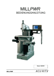
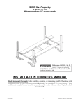
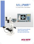
Download INSTALLATION MANUAL - Acu-Rite
Transcript
by INSTALLATION MANUAL Introduction Introduction MILLPWR® Installation Manual The User's Manual covers the functions of the MILLPWR® applications. The Installation Manual covers the installation of the MILLPWR® DRO. Symbols within Notes Every note is marked with a symbol on the left indicating to the Installer the type and/or potential severity of the note. General Information e.g. on the behavior of the MILLPWR®. Warning e.g. addition information of concern provided, or when a special tool is required for a function. Caution - Risk of electric shock e.g. when opening a housing, or insure power is off. MillPWR I II Introduction Table of Contents Introduction Symbols within Notes............................................................................................... I I - 1 Introduction to MillPWR System Overview .................................................................................................... 1 Preparation............................................................................................................... 2 Installation Requirements ........................................................................................ 2 Tools: X & Y Axis ..................................................................................................... 2 Tools for Z axis Installation ...................................................................................... 4 Additional tools required for installation of the “Z” axis. .................................... 4 I - 2 Mill Disassembly Table and Lead Screw removal................................................................................ 5 Removing the “X” axis hardware ....................................................................... 5 Removing the Table ............................................................................................ 5 Removing the “Y” axis hardware ....................................................................... 6 Removing the Leadscrews ................................................................................. 6 Removing the “Z” axis hardware ....................................................................... 7 Removing the Clutch Assembly.......................................................................... 8 II - 1 MillPWR Installation X Axis Ballscrew Installation .................................................................................... 9 Preparation.......................................................................................................... 9 Nut Block installation ........................................................................................ 10 Ballscrew installation ........................................................................................ 11 Vertical Alignment............................................................................................. 11 Horizontal alignment ......................................................................................... 12 Roll Pin installation ............................................................................................ 12 Y Axis Ballscrew Installation .................................................................................. 13 Table Installation .................................................................................................... 14 MillPWR III II - 2 Y Axis Motor Drive Installation Y axis Exploded view ............................................................................................. 15 Hardware list..................................................................................................... 15 Y Axis Motor Drive casting installation ............................................................. 16 Y axis Ballscrew Torque procedure .................................................................. 16 Y axis 60 T Pulley Installation............................................................................ 17 Y axis motor installation .................................................................................... 17 II - 3 X Axis Motor Drive Installation X axis Exploded view ............................................................................................. 18 Hardware list..................................................................................................... 18 X Axis Motor Drive casting installation ............................................................. 19 X axis Ballscrew Torque procedure .................................................................. 19 X axis Bearing sleeve Installation...................................................................... 20 X Axis Bearing Housing installation .................................................................. 20 X axis 60 T Pulley installation ............................................................................ 21 X Axis Motor Installation ................................................................................... 21 II - 4 X Axis Handle Installation X axis handle exploded view.................................................................................. 22 Hardware list..................................................................................................... 22 Securing the Bearing casting ............................................................................ 23 II - 5 Z Axis Quill Installation Z axis ballscrew exploded view ............................................................................. 24 Hardware list..................................................................................................... 24 Z Axis Nut Block Installation ............................................................................. 25 II - 6 Z Axis Motor Casting Installation Z axis motor casting exploded view ...................................................................... 31 Casting installation ............................................................................................ 32 Aligning the Z Axis Casting ............................................................................... 34 IV II - 7 Limit Switch Installation (rotary Encoder) Limit switch exploded view ................................................................................... 36 Hardware list..................................................................................................... 36 Limit switch installation .................................................................................... 37 Engagement Limit switch installation ............................................................... 37 II - 8 Precision glass scale Installation (optional) Exploded view ....................................................................................................... 39 Hardware list..................................................................................................... 39 Reading head bracket installation ..................................................................... 40 Scale Positioning............................................................................................... 40 Scale attachment .............................................................................................. 40 Reading head installation .................................................................................. 41 Limit switch installation .................................................................................... 41 Engagement Limit switch installation ............................................................... 41 II - 9 Z Axis Motor Installation Exploded view ....................................................................................................... 43 Hardware list..................................................................................................... 43 Motor installation .............................................................................................. 44 Belt Tension ...................................................................................................... 44 Console Installation........................................................................................... 44 II - 10 High/Low Range Switch Installation Bracket Installation............................................................................................ 45 Switch installation ............................................................................................. 45 II - 11 Cable Connections Cable attachment, and Installation.................................................................... 46 Cable Routing.................................................................................................... 47 Controller Routing ............................................................................................. 47 II - 12 Machine Tool Gib Adjustment Y Axis Gib.......................................................................................................... 48 X Axis Gib.......................................................................................................... 48 MillPWR V III - 1 Manual Tuning Initial Setup ............................................................................................................ 49 Flash Card ......................................................................................................... 49 Encoder Setup .................................................................................................. 49 Count direction ................................................................................................. 50 Changing count direction .................................................................................. 50 Confirm the control loop parameters ................................................................ 51 Travel Limits ..................................................................................................... 52 Introduction............................................................................................................ 53 Manual Tuning ....................................................................................................... 54 Accessing the Gain and Balance potentiometers ............................................. 54 X Axis Manual Tuning ....................................................................................... 55 Y Axis Manual Tuning ....................................................................................... 57 Re-attach Heat Sinks ........................................................................................ 58 Z Axis Manual Tuning ....................................................................................... 59 Re-attach Heat Sink .......................................................................................... 60 III - 2 Automatic Tuning X Axis Auto Tuning ........................................................................................... 61 Y Axis Auto Tuning ........................................................................................... 63 Z Axis Auto Tuning............................................................................................ 65 IV - 1 Trouble Shooting MillPWR Introduction............................................................................................................ 67 Using the Table................................................................................................. 67 VI I - 1 Introduction to MillPWR I - 1 Introduction to MillPWR System Overview Components: 1 2 3 4 5 6 7 8 9 MillPWR Console Mounting Arm (for Console) Acu-Rite’s Precision Glass Scales “Y” Axis Drive Housing “Y” Axis DC Motor Drive “X” Axis Drive Housing “X” Axis DC Motor Drive “Z” Axis Drive Housing “Z” Axis DC Motor Drive 1 9 2 8 7 This installation manual was written specifically for the Hardinge 3 ® Bridgeport Series I standard vertical knee mill (9" x 42" and 9" x 48" tables). If the MILLPWR® system is being installed on a different machine, additional installation instructions have been included with 6 1 4 5 ® this MILLPWR system. MillPWR 1 I - 1 Introduction to MillPWR Preparation Reviewing Section I - 2 Mill Disassembly on page 5, and Section II - 1 MillPWR Installation on page 9 prior to initiating the installation will help reduce installation time, and aid in having the MillPWR system operate correctly. Assemble together the recommended tools listed for the “X”, and “Y” axis installation. Recommended tools required for the “Z” are listed on page 4. Installation Requirements MillPWR requires a dedicated 110 volt (±20%). 20 amp, 50 - 60 Hz circuit and a 20 amp receptacle. Sufficient workspace should be provided to slide the table completely off the end of the saddle. The minimum space required is dependent on the actual table’s length. Installation Instructions for ACU-RITE’s precision glass scales are included with each scale. Instructions included with encoder mounting hardware kits supercede the scales instructions. Tools: X & Y Axis B A Special tools for the “X”, and “Y” axis installation are available. A B C D Ballscrew Alignment Tool ID 2003-7387 Ballscrew Torque Tool ID 2003-7397 Nut Block Drill Template ID 2003-7398 (subject to updates) Locknut Torque Tool ID 2003-7388 C D Additional tools required for installation of the “X”, and “Y” axis. Drills and Taps 1 2 3 4 Drill set: 7/32” through 1/2” Drill and Tap set: 4-40 through 3/8-16 1/4” Center Drill 3/8” Variable speed drill (heavy duty) Drivers 1 2 Hex Key set 0.05” through 1/2” (Ball driver) Hex Key set 1.5mm through 10mm (Ball driver) Hammers 1 2 2 Ball Peen (12 oz.) Plastic, soft-faced (7/8” - 1”face diameter I 1 2 3 4 5 6 7 8 9 10 I - 1 Introduction to MillPWR Measurement Tools & Levels Measuring tape - 12 Ft. Machinists’ Level - 4 in. (Tubular level optional) Machinists’ Square - 4 in. Caliper 12” - Dial, or Digital Depth Micrometers Dial Indicators .001”, and 0.0005” Indicator holder with magnetic base Measuring Standards (e.g. gage blocks) Feeler gages Pinned surface gage Pliers 1 2 3 Slip-joint Needle nose Diagonal side-cutter (small) Punches 1 2 3 Center punch Transfer punches 1/4” through 7/16” Pin set Screwdrivers 1 2 Phillips #2 pt. Small, non-conductive, flat tip Sockets 1 2 Hex Head set 1/8” through 5/8” 1” Socket Wrenches 1 2 3 4 5 6 Tap Handle 6” adjustable 12” adjustable Combination 3/8” through 11/16” Torque (5 - 75 ft-lb rating) Torque (20 - 250 in-lb rating) Miscellaneous 1 2 3 4 5 20 ft extension cord Files (flat, half-round, etc.) 1/4” Countersink Deburring tool Gear puller (optional) MillPWR 3 I - 1 Introduction to MillPWR Tools for Z axis Installation Special tool for the “Z” axis installation is available. A A Z-axis Locknut Torque Tool ID 2003-7447 Additional tools required for installation of the “Z” axis. Sockets 1 3/4” Socket Wrenches 1 2 3 4 5 6 7 8 9 9/16” Open End, (2) required 3/4” Open End 7/8” Open End 3/4” Open End Crowfoot 7/8” Open End Crowfoot Ratchet Wrench 3/8” or 1/2” and extension Hex Wrench set (Standard English with short arm) Provided by ACI - Hex Wrench M1.5 Provided by ACI - Hex Wrench M2 Miscellaneous 1 2 3 4 Retaining Ring Pliers Grease Gun high-quality lithium, soap-based grease I I - 2 Mill Disassembly I - 2 Mill Disassembly This section describes in detail the removal of components from the mill in preparation for the MillPWR installation. Shut off all electrical power to the machine before beginning. Table and Lead Screw removal A cart is required that is capable of supporting the table for removing it from the machine. Removing the “X” axis hardware U Remove vises, fixtures, etc. from the table. Table must be free from any components. U Remove the following components from each side of the table. 1 2 3 4 5 6 7 8 Jam nut Handle Dial locknut Dial Dial Holder Bearing retainer Bearings Bearing casting 8 5 7 1 2 6 3 4 If a power feed system is present, a right end bearing casting may have to be purchased from the machine’s manufacturer. In many cases, the left hand casting can be used on the right hand side. Removing the Table U Position the table so that it is centered over the saddle. U Remove the “X” axis gib. U Position the cart to either side of the knee centered under the table. U Raise or lower the knee so that the table is at the same height as the cart. U Slide the table onto the cart until it is clear of the saddle. Warning Insure that the table will be centered on the cart after it has been removed Slide the table directly off the saddle on to the cart. MillPWR 5 I - 2 Mill Disassembly Removing the “Y” axis hardware U Position the saddle all the way forward on the knee. U Remove the following components. Items noted with an asterisked (*) will be re-used. 1 2 3 4 5 6 7 8 Jam nut Handle Dial locknut * Dial * Dial Holder * Bearing retainer Bearings Bearing casting 4 5 7 6 1 3 8 2 Removing the Leadscrews U U U U U U Remove the two (2) screws (1) holding the “Y” axis leadscrew (2) to the nut block. Remove the leadscrew (2), and Acme nut (3) by placing the handle back on the leadscrew; and un-screwing it from the nut block. Repeat this procedure to remove the “X” axis leadscrew (4), (5), and (6). Disconnect the oil lines from the nut block (7). Remove the four (4) SHCS (8), and roll pin (9) that attach the nut block to the saddle. Save the SHCS for re-assembly. Remove the nut block (7) by turning it counter-clockwise 90°, then lifting up. 9 8 2 6 4 5 7 3 1 A pre-drilled nut block for the Hardinge Bridgeport® Series I standard milling machine is provided. All other makes and models will require the reuse of the existing nut block for the MillPWR system. Mark the orientation of the saddle way covers before removing. The disassembly of the “X”, and “Y” axis is now complete. If a “Z” axis control is also being installed proceed with “Removing the Z axis Hardware”. If this is a two (2) axis system being installed, proceed to the “Installation” section. 6 I U Remove the following components from the mill “Z” axis. 1 2 3 4 5 6 7 8 Handwheel Power feed transmission engagement crank Reverse trip ball lever and screw Snap ring Trip lever pin, feed trip lever, set screw, and steel nut Micro-screw quill stop Micrometer adjusting nut, or quick release nut assembly Quill stop nut and cap screw 1 I - 2 Mill Disassembly Removing the “Z” axis hardware Refer to the milling machines reference manual(s) when removing components from the mill head. 3 8 The Trip Feed assembly is now disabled. It is optional to remove it, as it will not interfere with milling functions. 4 2 7 6 5 MillPWR 7 I - 2 Mill Disassembly Removing the Clutch Assembly Disconnect the spindle motor from the power source U Remove the clutch arm cover 1. U Remove the spring-loaded clutch assembly 2 - 6. 1 2 3 4 5 6 Clutch arm cover Overload clutch Safety clutch spring Overload clutch locknut Clutch ring Overload clutch trip lever assembly 1 2 3 4 5 6 U With the spindle motor disconnected from the power source, remove the high/low range switch. The high/low switch will be relocated following the “Z” installation. The “Z” axis component removal is complete. To continue installing the MillPWR system, proceed to the section labeled “INSTALLATION” 8 8 I II - 1 MillPWR Installation II - 1 MillPWR Installation X Axis Ballscrew Installation Components: 1 2 3 4 X Axis Ballscrew X Axis Ballscrew hardware kit Nut Block Four (4) 3/8”-16 SHCS (previously removed) 4 2 Do not remove the ballnut from the ballscrew, it can not be re-assembled. 1 3 Preparation U Check that the saddle is completely clean. U Activate the oil pump and verify that oil flows freely to the gibs, saddle ways, and ballscrews. U Check the table ways, and gib for burrs, scratches, etc. If necessary, use a fine stone to smooth their surfaces. U Check that the gibs are flat. If necessary, replace them. Installing an auto-lube system is recommended to ensure that the ballscrew continuously receives oil. MillPWR 9 II - 1 MillPWR Installation Nut Block installation From the front of the mill, the nut block will be positioned, and installed into the saddle with the threaded holes facing to the left U Place the nut block into the saddle with the holes facing forward. U Rotate the nut block 90° clockwise. U Position the nut block so that the threaded holes are facing to the left of the saddle. 10 II II - 1 MillPWR Installation Ballscrew installation U Attach the nut block with the four (4) 3/8”-16 SHCS that were previously removed (Do Not Tighten). U Install an oil line fitting onto the flange of the ball nut. U Insert the ballscrew into the left side of the nut block. U Attach the ballnut to the nut block with three (3) 10-32 x 3/4” SHCS. U Torque the three (3) 10-32 x 3/4” SHCS to 30 in-lbs. U Connect the oil line to the fitting on the ball nut. The oil line fitting must not interfer with the underside of the table. Do Not Tighten the four (4) 3/8”-16 SHCS until noted to do so. Vertical Alignment U Place a pinned surface gage base with a .001” dial indicator attached onto the rear of the saddle surface. U Place the probe of the indicator so that it touches the top side of the ballscrew, and set to zero. U Without changing any settings to the indicator set up, move the base to the other end of the saddle and compare the two measurements. U If adjustment is necessary, raise one end of the nut block using shim stock to elevate it until both measurements are within 0.005” of each other. MillPWR 11 II - 1 MillPWR Installation Horizontal alignment U Now place the probe of the indicator so that it touches the front side of the ballscrew, and set it to zero. U Without changing any settings to the indicator set up, move the base to the other end of the saddle and compare the two measurements. U Position the nut block so that both measurements are within 0.005” of each other. U Torque the four (4) 3/8”-16 SHCS to 35 ft-lbs. Insure that alignment is maintained. Torque the nut block fasteners to 35 ft-lbs to properly secure it in place. Roll Pin installation Do not proceed without verification that the X axis ballscrew is properly aligned. U U Before proceeding, insure that the saddle way covers are clear. Drill two (2) 3/16” holes x 1” deep, one (1) on each side, through the nut block flange. Insert a 3/16 x 1” roll pin into each hole. Drive pins flush with top surface of nut block flange. 12 II II - 1 MillPWR Installation Y Axis Ballscrew Installation Components: 1 2 3 Y Axis Ballscrew Oil line (not shown) Oil line fittings (not shown) 3 2 Do not remove the ballnut from the ballscrew, it can not be re-assembled. Preparation U Position the saddle to the front of the knee, away from the column. 1 Y Axis Ballscrew installation U Feed the plastic oil line1, through the opening in the saddle to the right side of the nut block 2. U Install an oil line fitting 3, onto the flange of the ballnut on the right hand side (note it’s location). U Connect the oil line to the fitting on the ball nut. U Insert the ballscrew into the nut block. Note it’s orientation, and ensure that there is clearance for the crown gear. U Attach the ballnut to the nut block with three (3) 10-32 x 3/4” SHCS. U Torque the three (3) 10-32 x 3/4” SHCS to 30 in-lbs. 1 2 3 No alignment is necessary for the Y axis ballscrew. U U U Cut the oil line to length, and connect it to the oil line on the machine. Insure that the oil line does not interfere with the crown gear, or other obstructions. Slide the saddle through it’s full travel while insuring that the oil line is free to move with the saddle movement. The Y axis scale should be installed at this point. Use the bracket kit instructions to install the encoder. MillPWR 13 II - 1 MillPWR Installation Table Installation Components: 1 2 3 Table X axis gib X axis gib adjustment screw Preparation U U U U Check that the saddle ways are clean, free of chips, dirt, and are in good condition. Activate the oil pump. Verify that the gibs, saddle ways, and ballscrews are receiving oil. Position the X axis gib locks so that there is clearance for the table to slide back on to the saddle. Coat the saddle ways with oil. Ensure that the X axis gib locks do not fall into the saddle. Table installation U Inserting the table into the right side of the saddle, move the X axis ballscrew to the left until the end of the screw is flush with the right side of the saddle. Do the opposite, if inserting into the left side of the saddle. U Adjust the knee height level to the table, same as done when it was removed. U With table properly aligned to the saddle, slide the table onto the saddle. U Oil the gib, and insert it into position. Attach the gib adjustment screw, but do not tighten at this time. Inspect gib prior to installing. If damaged, or worn, replace. 14 II II - 2 Y Axis Motor Drive Installation II - 2 Y Axis Motor Drive Installation Y axis Exploded view The bearing and outer bearing retainer plate have been factory installed to the proper torque specification. Do not remove them Hardware list 22 24 20 18 21 14 15 16 19 23 17 13 12 8 5 9 11 27 6 3 2 4 31 29 10 7 32 25 30 28 26 1 1 2 3 4 5 6 7 8 9 10 11 12 13 14 15 16 ID 2003-373 ID 2003-305 ID 4100-176 ID 385004-165 ID 2003-372 ID 387900-124 ID 387900-115 ID 385004-164 ID 2013-367 ID 2003-346 ID 2003-374 ID 2003-370 ID 4180-121 ID 2013-363 ID 2013-364 ID 2013-365 Arbor Washer Pulley, 60T 1/4-20 x 1/2” SHSS 3/8-16 x 1-1/4” SHCS 3/8” Flat washer Roll pin, 3/16 Dia. x 1” lg. Spanner lock nut 1/4-20 x 1/2”SHCS Bearing retainer Angle contact bearing Preload bearing shim Seal, Nilos-Ring Key, 1/8” sq. x 1” lg. Ballscrew - 12” Ballscrew - 15” Ballscrew - 16” 17 18 19 20 21 22 23 24 25 26 27 28 29 30 31 32 ID 385004-401 ID 387900-284 ID 387900-119 ID 387900-114 ID 387900-175 ID 2013-319 ID 385004-161 ID 2003-307 ID 2013-304 ID 4100-154 ID 4180-123 ID 4150-111 ID 2013-317 ID 2013-210 ID 4100-118 ID 4180-121 Jam Nut 1/2-20 Handwheel Lock nut (replacement) Dial, (replacement) Dial Holder (replacement) Cover, Y axis housing 10-24 x 5/8” SHCS Belt Pulley, 30T 10-32 x 1/4” SHSS Plug 5/16 Locking Hex flange nut Y axis housing DC Motor assembly 5/16-18 x 1-1/4” SHCS key, 1/8 Square x 1” lg. All numbers (XX) in the following section refer to the listed items in this exploded view unless otherwise specified. MillPWR 15 II - 2 Y Axis Motor Drive Installation Y Axis Motor Drive casting installation U Move the saddle to approximately 3” from the front of the knee. U Attach the Y axis housing (29) to the front of the knee with four (4) 3/8-16 x 1-1/4” SHCS (4), and 3/8 Flat washer (5). Do not fully tighten fasteners at this time. U Place the alignment tool, see "Ballscrew Alignment Tool ID 2003-7387" on page 2, (A), over the ballscrew shaft, and into the bearing bore. U Adjust the housing until the tool slides freely over the shaft, and into the bearings. Do not remove the tool at this time. U Secure the housing in place by securing the four (4) 3/8-16 x 1-1/4” SHCS, torque to 35 ft-lbs. A Warning The tool must slide freely over the shaft, and into the bearings after the fasteners have been torque. U Install the Roll pin, 3/16 Dia. x 1” lg. (6). Drill a 3/16” diameter hole through both the housing and knee casting. Guide holes have been provided in the housing, one on each side to the bearing retainer plate (9). Insure that no chips fall into the bearing area. Y axis Ballscrew Torque procedure U Remove the alignment tool, and turn the ballscrew clockwise (out), into the bearings. Insure that the bearings seat properly on the ballscrew shaft. With bearings seated, do not move the shaft. U Insert the spanner lock nut (7) on to the ballscrew shaft with the tapered side facing the machine, and hand tighten. U Place the torque tool, see "Locknut Torque Tool ID 2003-7388" on page 2, over the shaft, and onto the spanner lock nut. U Place the square key (13) in the front slot of the ballscrew. U Place the torque tool, see "Locknut Torque Tool ID 2003-7388" on page 2, over the shaft, and key. U Place a spanner wrench onto the Locknut Torque Tool, (or use an adjustable wrench). U While holding the spanner wrench, torque the spanner nut to 50 ft-lbs by turning the ballscrew counter clock wise with the torque wrench attached to the Ballscrew Torque Tool. U Remove all tools. 16 II II - 2 Y Axis Motor Drive Installation Y axis 60 T Pulley Installation U Insert the 1/8” square key into the key slot closest to the ballscrew (motor housing). U Slide the 60 T pulley (2), flat side towards the mill, over the 1/8” square key, up against the journal on the ballscrew. U Secure the pulley in position by tightening the two (2) 1/4-20 x 1/2” SHSS (3) to 48 in-lbs of torque. U Place the belt (24) onto the 60 T pulley. Y axis motor installation The motor mounting plate allows the motor to be rotated incrementally at 45°. This feature is provided to allow clearance from machine components if necessary. U U U U U U U U U Insert the motor assembly (30) through the rear of the housing. Attach the motor to the housing with four (4) 5/16-18 x 1-1/4 SHCS (31), and four (4) 5/16 locking Hex Flange nuts (28). Do not tighten at this time. Place the square key in the slot on the shaft of the motor. Slide the 30 T pulley (25), flat side towards the motor, and position in line with the 60 T pulley. Secure the pulley in position by tightening the two (2) 10-32 x 1/4” SHSS (26) to 48 in-lbs of torque. Place the belt on the pulley. Apply pressure on the belt, but not excessive, secure the motor in place to 15 ft-lbs of torque. Place the cover plate (22) on the housing, and secure in place with (6) 10-24 x 5/8” SHCS (23). Place a washer (1) onto the ballscrew shaft. Re-install the dial assembly. If additional clearance is needed, add another washer. Insert the handwheel (18) on to the shaft, and lock in place with the jam nut (17). MillPWR 31 30 28 25 26 17 II - 3 X Axis Motor Drive Installation II - 3 X Axis Motor Drive Installation X axis Exploded view The bearing and outer bearing retainer plate have been factory installed to the proper torque specification. Do not remove them Hardware list 22 24 25 21 20 19 23 15 18 11 13 17 16 14 9 12 10 8 7 4 26 6 3 5 2 1 1 2 3 4 5 6 7 8 9 10 11 12 13 14 15 16 17 18 19 20 21 22 23 24 25 18 ID 4100-118 ID 2013-210 ID 2013-304 ID 4100-154 ID 385004-164 ID 2013-313 ID 4150-111 ID 2103-306 ID 4180-121 ID 2003-305 ID 4100-176 ID 387900-115 ID 385004-164 ID 2013-367 ID 2003-305 ID 2003-374 ID 2003-305 ID 2003-370 ID 387900-399 ID 4100-142 ID 2003-372 ID 2013-311 ID 2013-348 ID 385032-105 5/16-18 x 1-1/4” SHCS DC Motor assembly Pulley 30 T 10-32 x 1/4” SHSS 1/4-20 x 1/2” SHCS Cover, X Axis Housing 5/16-18 Locking Hex Flange Nut Belt key, 1/8 Square x 1” lg. Pulley, 60 T 1/4-20 x 1/2” SHSS Spanner lock nut 1/4-20 x 1/2” SHCS Bearing retainer Angle contact bearing Preload bearing shim Angle contact bearing Seal, Nilos-Ring Roll Pin, 3/16 x 2” lg. 3/8-16 x 2” SHCS 3/8” Flat washer X axis housing Cover Plate 8-32 x 3/8” BHCS X Axis Ballscrew II II - 3 X Axis Motor Drive Installation All numbers (XX) in the following section refer to the listed items in this exploded view unless otherwise specified. X Axis Motor Drive casting installation U Position the ballscrew, and table approximately centered on the saddle. U Attach the X axis housing (22) to the left end of the table with four (4) 3/8-16 x 1-1/4” SHCS (20), and 3/8 Flat washer (21). Do not fully tighten fasteners at this time. U Insert the alignment tool, see "Ballscrew Alignment Tool ID 2003-7387" on page 2, over the shaft, and into the bearing bore. U Adjust the housing until the tool slides freely over the shaft, and into the bearings. Do not remove the tool at this time. U Secure the housing in place by securing the four (4) 3/8-16 x 1-1/4” SHCS, torque to 35 ft-lbs. Warning The tool must slide freely over the shaft, and into the bearings after the fasteners have been torque. U Install the Roll pins, 3/16 Dia. x 2” lg. (19). Drill a 3/16” diameter hole through both the housing, and into the end of the table. Guide holes have been provided in the housing, one on each side of, and above the bearing retainer plate (14). Insure that no chips fall into the bearing area. X axis Ballscrew Torque procedure U Remove the alignment tool, and turn the ballscrew from the left side of the table, clockwise (out), into the bearings. Insure that the bearings seat properly on the ballscrew journal. With the bearings seated, do not move the ballscrew. U Insert the spanner lock nut (12) on to the ballscrew shaft with the tapered side facing the machine, and hand tighten. U Place the torque tool, see "Locknut Torque Tool ID 2003-7388" on page 2, over the shaft, and onto the spanner lock nut. U Place a spanner wrench onto the Locknut Torque Tool, (or use an adjustable wrench). Proceed with the next step. Refer to the exploded view in the next section, II-4 for the following steps. MillPWR 19 II - 3 X Axis Motor Drive Installation X axis Bearing sleeve Installation U Insert the Bearing sleeve (16), or sleeve (14), or spacer (15) onto the right end of the ballscrew (correct pieces, and quantities are included). See "X axis handle exploded view" on page 22.. X Axis Bearing Housing installation U U U U U U U U Insert the bearing housing with the bearing installed, onto the right end of the ballscrew. Slide the assembly up to the end of the table, and insure that the bearing is seated on the bearing sleeve, or sleeve bearing journal. Check that the bearing sleeve, or sleeve has extended through to the outside edge of the bearing. To extend the bearing sleeve, or sleeve if needed, remove the housing, and bearing sleeve, or sleeve. Insert arbor washer(s) as needed. Re-install the bearing sleeve, or sleeve, and housing. Attach the bearing housing to the table using the existing fasteners. Do not tighten fasteners at this time. Place the square key (3) in the slot at the end of the ballscrew. Place the torque tool, see "Ballscrew Torque Tool ID 2003-7397" on page 2, over the shaft, and key. With the spanner wrench locked into position at the casting end, torque the spanner nut to 50 ft-lbs at the bearing end by turning the ballscrew clock wise with the torque wrench (attached to the Ballscrew Torque Tool). The spanner, or adjustable wrench will lock it’s self in place in the casting while the spanner nut is being torque. Assistance should not be required. U Remove all tools from the machine). 20 II II - 3 X Axis Motor Drive Installation X axis 60 T Pulley installation The motor mounting plate allows the motor to be rotated incrementally at 45°. This feature is provided to allow clearance from machine components if necessary. U U U U Insert the 1/8” square key into the key slot on the ballscrew motor housing end. Slide the 60 T pulley (10), flat side towards the mill, over the 1/8” square key, up against the journal on the ballscrew. Secure the pulley in position by tightening the two (2) 1/4-20 x 1/2” SHSS (11) to 48 in-lbs of torque. Place the belt (8) onto the 60 T pulley. X Axis Motor Installation U Attach the X axis motor drive housing cover (6) with eight (8) 1/4-20 x 1/2” SHCS (5). U Position the motor assembly so that the drive belt is on the 30 T pulley on the motor. Attach the motor to the housing with four 5/16-18 x 1-1/4 SHCS (31), and 5/16 locking Hex Flange nut (28). Do not tighten. Apply pressure on the belt by pushing on the motor, but not excessive, secure the motor in place to 15 ft-lbs of torque. Re-install the rear access cover. U U U MillPWR 21 II - 4 X Axis Handle Installation II - 4 X Axis Handle Installation X axis handle exploded view Completing the handle assembly. Hardware list 11 12 10 9 8 16 7 15 6 14 5 4 3 13 1 2 3 4 5 6 7 8 9 10 11 12 13 14 15 15 16 ID 4100-186 ID 4160-901 ID 4180-121 ID 387900-121 ID 387900-118 ID 387900-119 ID 387900-175 ID 387900-195 ID 2003-373 ID 2003-315 ID 387900-196 ID 2013-904 ID 2013-901 ID 2013-903 ID 2013-910 2 1 1/4-20 x 1” FHCS Retaining washer Key, 1/8 Square x 1” lg. Handwheel Lock Nut (replacement only) Use existing Dial (replacement only) Use existing Dial Holder (replacement only) Use existing Radial bearing Arbor washer Existing fasteners Bearing housing (replacement only) Use existing Ballscrew .03” Shim washer Sleeve .525” lg. Bearing sleeve 1” lg. Bearing sleeve 3” lg. Spacer 1” lg. All numbers (XX) in the following section refer to the listed items in the above exploded view unless otherwise specified. 22 II U U U U II - 4 X Axis Handle Installation Securing the Bearing casting U Position the table to the left so that it’s nearly flush with the right side of the knee. This aids in the alignment of the casting. U Torque each fastener to 35 ft-lbs. Slide the shim onto the ballscrew, and position the dial holder assembly onto the ballscrew. Insert the 1/8” square key (3) into the key slot on the ballscrew. Slide the Handwheel (4) onto the end of the ballscrew. Secure the Handwheel with the Retaining washer (2) and flat head screw (1). MillPWR 23 II - 5 Z Axis Quill Installation II - 5 Z Axis Quill Installation Z axis ballscrew exploded view Hardware list 13 17 11 9 7 8 12 10 16 5 3 4 6 14 1 15 2 1 2 3 4 5 6 7 8 9 10 11 12 13 14 15 16 17 24 ID 2003-439 ID 382250-155 ID 2003-433 ID 2003-450 ID 4100-153 ID 2003-432 ID 2003-434 ID 4100-109 ID 4100-157 ID 2003-421 ID 67200-454 ID 4150-900 ID 2003-396 ID 4100-150 ID 384600-093 ID 2003-420 ID 2003-438 Quick Release Knob 1/4-20 x 1/4” SHSS Shaft Spacer 8-32 x 3/4” SHCS Clamp Shaft Retainer 1/4-20 x 3/4” SHCS 3/8-24 x 1-1/2” SHCS Nut Block Drive Key 1/2-13 Ext. Hex Coupling Nut Ballscrew 6-32 x 1/4” SHSS 10-24 x 7/8” SHCS Disengage Feed bracket Alignment Bushing II II - 5 Z Axis Quill Installation All numbers (XX) in the following section refer to the listed items in the above exploded view unless otherwise specified. Check the actual Quill Travel. During this installation, in order not to cause damage to the quill skirt, the recommended travel must not be exceeded. The spindle must be removed in order to drill and tap the quill for the nut block. Refer to the machines operator/reference manual. Z Axis Nut Block Installation U Attach the disengage bracket (16) on to the shaft where the engagement crank was removed. See "Power feed transmission engagement crank" on page 7.. Use the 10-24 x 7/8”SHCS (15). Insert the 6-32 x 1/4” SHSS (14). Secure in place. The following steps are to be preformed by removing one head locking nut at a time. U U U U Remove each head locking nut in the order show, replacing each, one at a time with 1/2-13 x 1-3/4”extension coupling nut (12). Tighten each nut to 25 ft-lbs. Repeat the tightening procedure using the same sequence to 50 ft-lbs each. The spindle must be properly aligned. Refer to the machines operator/reference manual to align the spindle at this time. Insert the Alignment Bushing (17) into the lower casting tab. 17 U Remove the “Quick Release” knob (1) from the Nut Block assembly. The nut block will mount to the quill using the quill stop mounting hole. Insure that the quill is positioned to allow clearance for the nut block mounting surface. U With the Quill locked in position (quill must not come out of the machine), remove the Spindle. MillPWR 25 II - 5 Z Axis Quill Installation U U U U U U U U Attach the Nut Block assembly to the Quill with the 3/8-24 x 1-1/2” SHCS (9). Do not fully tighten fastener at this time. Inspect around the mounting surface of the nut block assembly to insure that clearance is provided between the casting, and nut block. The mounting surface of the nut block is contoured to match the radius of the quill. This makes the nut block self aligning when secured in place. If it becomes necessary for some reason to check the alignment, mount a dial indicator to a magnetic base, and attach it to the table top. Position the indicator needle to the inner wall of the nut blocks vertical bored hole. Set the indicator to “0.000”. With the quill still locked, raise, and lower the “knee” to indicate the inside bore from top to bottom. The measured reading must be within 0.001” from top to bottom of the bore. To align the nut block, use an adjustable wrench as shown. U Repeat the indicating procedure (raise, and lower the “knee”, to indicate the inside bore from top to bottom. Making adjustments as necessary until the alignment is within 0.001” from top to bottom of the bore. 26 II Remove the quick release components from the nut block (10). U With the correct alignment being maintained, transfer punch the lower hole in the nut block to the quill. U Remove the nut block, and drill, and tap the hole location for a 1/4-20 through. Clean the inside, and outside of the quill thoroughly, removing all chips and debris. Test fit the nut block with both mounting screws. Insure that neither screw protrudes into the spindle bore. If necessary, grind the screws to the correct length. U U MillPWR II - 5 Z Axis Quill Installation U 27 II - 5 Z Axis Quill Installation U U U U Reinstall the spindle into the quill. Insert the drive key into the nut block counter bore hole. The key may have to be ground, or filed to allow the nut block to seat properly. U Apply Loctite onto the threads of the 3/8-24 x 1-1/2”SHCS, and the 1/4-20 x 3/4”SHCS. Attach the nut block with both screws. U Repeat the alignment procedure of the nut block. The nut block must be properly aligned at this time, prior to continuing with the installation. U Torque the 3/8-24 x 1-1/2” SHCS to 30 ft-lbs, and the 1/4-20 x 3/4” SHCS to 9 ft-lbs. 28 II Reinstall the Engage/Disengage mechanism. U Insert the ballscrew into the nut block from the top. MillPWR II - 5 Z Axis Quill Installation U 29 II - 5 Z Axis Quill Installation U Tighten the screws of the Engage/Disengage mechanism until the heads of the screws are flush with the plate. U Attach the quick release knob. Using the quick release knob, secure the ball screw in place. U U Remove the plug from the ball screw (and save). Install the grease fitting into the ball screw. 30 II II - 6 Z Axis Motor Casting Installation II - 6 Z Axis Motor Casting Installation Z axis motor casting exploded view Items 13 through 17 have been factory installed. 20 19 18 17 16 15 14 13 12 1 6 3 11 10 3 2 9 8 7 5 4 MillPWR 31 II - 6 Z Axis Motor Casting Installation Hardware list 1 2 3 4 5 6 7 8 9 10 11 12 13 14 15 16 17 18 19 20 ID 2013-391 ID 4100-158 ID 4160-114 ID 4100-155 ID 2003-485 ID 4150-106 ID 4150-107 ID 4160-113 ID 385026-104 ID 2003-413 ID 2003-416 ID 4100-151 ID 2003-457 ID 2003-458 ID 2003-457 ID 2003-412 ID 4100-155 ID 2003-443 ID 2003-417 ID 4180-121 Z Axis Housing 1/-13 x 2” HHMS 1/2” Flat washer 10-32 x 1/2” SHCS Ball Nut Stop 1/2-13 Hex Nut 3/8” Hex Nut 3/8” Flat washer 10-32 x 3/4” SHCS Bearing Retainer Radial bearing 3/8-16 x 2” HHCS Angle Contact bearing Preload Bearing Shim Angle Contact bearing Bearing Retainer 10-32 x 1/2” SHCS Spanner nut Pulley 24 T Key, 1/8” sq. x 1” lg. All numbers (XX) in the following section refer to the listed items in the previous exploded view unless otherwise specified. U U Lower the nut block to the bottom of the quill travel. Position the ballscrew approximately 3-1/2” from the top of the ballscrew nut. The bearing assembly, 13 through 17, have been factory installed. Casting installation Insert the ballscrew through the bottom of the casting (1), then lift over the top of the ballscrew. Set bearing bore onto the top of the ballscrew. U 32 II U U II - 6 Z Axis Motor Casting Installation U Install the 3/8-16 x 2” HHCS (12), through the hole in the casting, and the lower bushing. Attach the 3/8 x 1/2 Hex nut (7), and flat washer (8). Leave loose at this time. Raise the quill until the top to the ballscrew shaft seats into the top bearings. Place the radial bearing (11), into the bearing retainer (10). When attaching the bearing retainer, insure that the bearing slides over the shaft of the ball screw. U Attach the retainer with four (4) 10-32 x 5/8” SHCS (9). Do not tighten fasteners at this time. MillPWR 33 II - 6 Z Axis Motor Casting Installation U Using the quill handle, position the ballscrew nut to about 1/4” from the top of the ballscrew travel. U Install the spanner nut to the top of the ballscrew (18), (taper side of the nut should be downward towards the bearings). Place the spanner nut torque tool over the spanner nut. See "Z-axis Locknut Torque Tool ID 2003-7447" on page 4.. Using a torque wrench, tighten the spanner nut to 30 ft-lbs holding the bottom of the ballscrew in place with a 9/16” open end wrench. U Aligning the Z Axis Casting U Referring to the exploded view drawing, insert four (4) 1/2-13 x 2” SHCS (2) with flat washer (3) through the casting. U Insert a second set of four (4) 1/2” flat washers (3), and attach four (4) 1/2-13 hex nuts (6). U Attach the casting to the coupling hex nuts previously installed onto the quill. Do not secure at this time. 34 II U U U U U U U U U U U Run the quill up, and down through it’s full travel. Position the quill at the top of it’s travel, until the top of the ball nut reaches the stop. Position the face of the casting so that it is parallel with the face of the quill horizontally. Place an indicator, or two indicators as shown, and set to 0.000”. This will be used as a reference while securing the casting in place. While monitoring the indicator(s), secure the upper casting by fully tightening the mounting bolt on one side. The indicator should remain at it’s 0.00” reading ±0.001”. The face of the casting should be parallel with the face of the quill horizontally. Move the indicator to the other side as shown (if one is being used), and secure the other mounting bolt. Lower the nut block to the end of it’s travel. Relocate the Dial indicator, and repeat the same process. Raise, and lower the nut block. It will move freely through it’s entire travel. If any binding of the ballscrew is felt, repeat the alignment procedure. II - 6 Z Axis Motor Casting Installation U Lower the quill until the shaft bottoms out. Torque all four (4) 10-32 x 5/8” SHCS to 60 in-lbs. Fully tighten the 3/8-16 x 2” HHCS (12). Raise, and lower the nut block to insure it moves freely through it’s entire travel. If any binding of the ballscrew is felt, repeat the alignment procedure. U Insert the 1/8” square key x 1” lg. (20) into the slot location at the top of the ballscrew. U Attach the pulley, sliding it against the journal. Secure in place by tightening the two set screws. If necessary, remove the oil cap to attach the pulley. Reinstall the oil cap once the pulley has been installed. The following section is for a MILLPWR® system that is using a rotary encoder for the Z axis. If the MILLPWR® system that is being installed is using a liner glass scale encoder, see "Precision glass scale Installation (optional)" on page 39. MillPWR 35 II - 7 Limit Switch Installation (rotary Encoder) II - 7 Limit Switch Installation (rotary Encoder) Limit switch exploded view Hardware list 9 11 13 12 6 8 5 1 14 7 4 12 6 10 5 4 2 3 1 2 3 4 5 6 7 8 9 10 11 12 13 14 ID 385004-161 ID 2003-439 ID 2013-393 ID 387530-120 ID 4100-152 ID 2003-435 ID 4100-184 ID 2003-246 ID 2003-440 ID 4180-131 ID 2013-441 ID 2003-436 ID 387901-139 ID 4100-159 10-24 x 5/8” SHCS Quick release knob Cover plate 4-40 x 1/4”PHMS 2-56 x 1/2” PHMS Switch plate holder 10-32 x 3/8” BHCS Pointer Nylon brush (not shown) 1/4” Cable clamp (not shown) 8-32 x 3/8” BHCS (not shown) Limit switch Limit switch 6-32 x 1/4” SHCS All numbers (XX) in the following section refer to the listed items in the previous exploded view unless otherwise specified. 36 II II - 7 Limit Switch Installation (rotary Encoder) The upper and lower limit switches are supplied attached to the mounting plates. The nylon brushes are factory installed to the inside of the cover plate. The engagement switch, (13) is a part of the wire harness. Limit switch installation A quick change tooling system requires that the upper limit switch be positioned where resistance can be felt on the quill quick feed lever. U U U U Remove the Quick Release knob. Attach the upper, and lower limit switch mounting plates to the casting with the 4-40 x 1/4” PHMS (4). Do not tighten in place at this time. Adjust the upper limit switch so that it trips when the nut block is within 0.05” to 0.10” of it’s upper max travel. Secure bracket in place. Adjust the lower limit switch so that it trips when the nut block is within 0.05” to 0.10” of it’s lower max travel. Secure bracket in place. Engagement Limit switch installation U U U Attach the limit switch (14) to the quick release assembly with (2) 6-32 x 1/4” BHCS (13). Re-attach the quick release knob. Turn the knob clockwise until it is fully closed. Adjust the limit switch until the switch trips. Secure the bracket, and switch in position. Loosen the quick release clamp, and the switch should open. Turn the knob clockwise until it is fully closed, this is when the switch should close. Insure that the switch is properly positioned. MillPWR 37 II - 7 Limit Switch Installation (rotary Encoder) U Route the wire harness inside the casting as shown. If switches have been removed from the wire harness, complete the following. 1 Black lead Connect black lead from engagement switch. Longest lead Connect long black lead from reader head cable. White lead Connect white lead from engagement switch. White lead Connect white lead from reader head cable. 1/4” Cable clamp Attach engagement harness to the casting with the 1/4” cable clamp. Cable strain Place the strain relief around the cable, and relief insert into the slot provided with the clamp on the top side. Adhesive clamp Attach three (3) clamps as shown, and attach the cable as shown Grease Fitting Using a high quality lithium, soap-based grease, add grease until it begins to escape from the ballscrew nut. Plug Remove grease fitting (8), and replace with previously removed plug. Save fitting for future use. 2 3 4 5 6 7 8 9 U Insure that the ball nut has been properly greased. Use high quality Lithium soap based grease. U Attach the pointer as shown, items (7), and (8). Refer to the exploded view. Attach the cover plate (3), with the fasteners (1), and attach the quick release know (2). Refer to the exploded view. U 38 6 8 1 2 7 5 3 7 4 7 II II - 8 Precision glass scale Installation (optional) II - 8 Precision glass scale Installation (optional) Exploded view Hardware list 9 11 12 8 7 10 1 5 4 5 6 6 4 2 3 1 2 3 4 5 6 7 8 9 10 11 12 ID 385004-161 ID 2003-439 ID 2013-393 ID 387530-120 ID 4100-152 ID 2003-435 ID 4100-184 ID 385101-103 ID 4180-131 ID 385032-105 ID 2003-431 10-24 x 5/8” SHCS Quick release knob Cover plate 4-40 x 1/4”PHMS (not shown) 2-56 x 1/2” PHMS Switch plate holder 10-32 x 3/8” BHCS Encoder M4 x 8mm SHSS (not shown) 1/4” Cable clamp (not shown) 8-32 x 3/8” BHCS (not shown) Reading head bracket All numbers (XX) in the following section refer to the listed items in the previous exploded view unless otherwise specified. The upper and lower limit switches are supplied attached to the mounting plates. Nylon brushes are factory installed to the inside of the cover plate. MillPWR 39 II - 8 Precision glass scale Installation (optional) Reading head bracket installation U Attach the reading head bracket with two (2) 8-32 x 3/8”BHCS (11), and (12). U Position the bracket so that it is flush with the front of the nut block. 12 11 Scale Positioning U U Place the scale into the casting as shown. The top end of the scale rest against the underside of the casting. The scale sets on two machined surfaces, and inserts into “L” shaped hooks. Scale attachment U U Using two (2) M4 x 8mm SHSS (9), apply loctite to the threads and insert into the left side of the casting. Fully tighten both screws, securing the scale in place. 40 II II - 8 Precision glass scale Installation (optional) Reading head installation U Move the quill so that the reading head bracket mounting holes align with the reading head casting mounting holes. U Insert the two (2) 8-32 x 3/4” low head SHCS through the reading head, and into the bracket. Do not tighten. U Place loctite on the three (3) M3 x 12mm SHSS, and insert each into the reading head. Adjust each screw so that when lightly tightening, stop as soon as resistance is felt. U Fully tighten the two (2) 8-32 x 3/4” low head SHCS. U Remove the two (2) alignment brackets (A) from the reading head, and scale case. A Limit switch installation U Attach the upper, and lower limit switch mounting plates to the casting with the 4-40 x 1/4” PHMS (4). Do not tighten in place at this time. U Adjust the upper limit switch so that it trips when the nut block is within 0.05” to 0.10” of it’s upper max travel. Secure bracket in place. U Adjust the lower limit switch so that it trips when the nut block is within 0.05” to 0.10” of it’s lower max travel. Secure bracket in place. A quick change tooling system requires that the upper limit switch be positioned where resistance can be felt on the quill quick feed lever Engagement Limit switch installation U Attach the bracket to the quick release assembly with (2) 6-32 x 1/4” SHCS (13). U Re-attach the quick release knob. Turn the knob clockwise until it is fully closed. Adjust the limit bracket until the switch trips. Secure the bracket in position. U Loosen the quick release clamp, and the switch should open. Turn the knob clockwise until it is fully closed, this is when the switch should close. Insure that the switch is properly positioned. MillPWR 41 II - 8 Precision glass scale Installation (optional) U Route the wire harness inside the casting as shown. If switches have been removed from the wire harness, complete the following. 1 2 Black lead Black lead Connect long black lead from motor housing. Connect black lead from nut block limit switch. White lead Connect white lead from nut block limit switch. Black lead Connect short black lead from motor housing. 1/4” Cable clamp Attach engagement harness, and reading head cable to the casting with the (2) 1/4” cable clamps. Cable strain Place the strain relief around the cable, and relief insert into the slot provided with the clamp on the top side. Adhesive clamp Attach two (2) clamps as shown, and attach the cable as shown Grease Fitting Using a high quality lithium, soap-based grease, add grease until it begins to escape from the ball screw nut. Plug Remove grease fitting (8), and replace with previously removed plug. Save fitting for future use. 3 4 5 6 7 8 9 U U 8 6 1 2 5 5 7 3 4 7 Insure that the ball nut has been properly greased. Attach the cover plate (3), with the fasteners (1), and attach the quick release know (2). Refer to the exploded view. 42 II II - 9 Z Axis Motor Installation II - 9 Z Axis Motor Installation Exploded view Reattach the quick release knob Hardware list 1 2 3 4 5 6 7 8 9 10 ID 2003-210 ID 2013-392 ID 385004-161 ID 4150-111 ID 2013-437 ID 2013-418 ID 4180-121 ID 2013-348 ID 385032-105 ID 4100-118 Z Axis Motor Assembly Cover plate 10-24 x 5/8” SHCS 5/16 Hex locking flange nut Belt Pulley, 24 T 1/8” square key x 1” lg. Access plate 8-32 x 3/8” BHCS 5/16-18 x 1-1/4” SHCS (not shown) 1 10 All numbers (XX) in the following section refer to the listed items in this exploded view unless otherwise specified. 2 3 U U U Position the belt over the ball screw pulley (5). Attach the top cover (2) with six (6) 10-24 x 5/8”BHCS (3) Remove the Access cover (8) if it is installed. 4 6 5 7 8 9 MillPWR 43 II - 9 Z Axis Motor Installation Motor installation U Attach the motor to the casting assembly with four (4) 5/16-18 x 1-1/4” SHCS (10), and 5/16 Hex locking flange nut (4). Do not tighten fasteners. U Reach up through the access hole on the underside of the casting, and place the belt around the motor pulley. Belt Tension U Put tension on the belt by sliding the motor assembly away from the spindle. U Tighten the four motor mounting bolts while maintaining tension on the belt. U Attach the access cover plate. Console Installation U Use the instructions supplied with the arm mounting kit to install the console. 44 II II - 10 High/Low Range Switch Installation II - 10 High/Low Range Switch Installation The High/Low Range switch is relocated to the side of the Z axis casting Bracket Installation U Attach the mounting bracket with two (2) 10-32 x 1/2” SHCS. Switch installation U U Ensure that the spindle motor is disconnected from its power source. Attach the high/low range switch on to the bracket. A cable is provided to re-wire the switch if it has become necessary. MillPWR 45 II - 11 Cable Connections II - 11 Cable Connections Refer to the following chart to connect the cables. Failure to correctly connect all cables could result in a table run-a-way condition when powered up. This view is typical to all three (3) motor housings Cable attachment, and Installation 1 2 3 4 1 2 3 4 1 2 3 4 U U U X Axis X Axis X Axis X Axis Y Axis Y Axis Y Axis Y Axis Z Axis Z Axis Z Axis Z Axis To Z motor 2 From Y motor 1 From X Axis encoder To Controller, X Axis Servo To X motor 2 From Controller, Servo Power From Y Axis encoder To Controller, Y Axis Servo Open From X motor 1 From Z Axis encoder To Controller, Z Axis Servo 2 3 1 4 Connect the X axis scale cable (3) to the X axis motor assembly. Connect the Y axis scale cable (3) to the Y axis motor assembly. Connect the Z axis scale cable (3) to the Z axis motor assembly. If the system that is being installed is not equipped with the Z axis control, connect the Z axis encoder to the Z axis encoder connector on the rear of the operator console. When using the Multiple Scale Coupling feature, connect the cable for the encoder mounted on the knee to the W-axis encoder connector located on the rear of the operator console. U U U U U U Connect the X-axis motor assembly cable (4) to the X axis servo connector located on the rear of the operator console. Connect the Y-axis motor assembly cable (4) to the Y axis servo connector located on the rear of the operator console. Connect the Z-axis motor assembly cable (4) to the Z axis servo connector located on the rear of the operator console. Connect the X axis AC power cable (1) to the Z Axis motor housing (2). Connect the X axis cable (2) to the Y Axis motor housing (1). Connect the Y axis cable (2) to the Controller “Servo Power”. 46 II View of the rear of the console. II - 11 Cable Connections U Cable Routing U Route all cables in a neat, and orderly fashion. Keep cables approximately 16” above the floor. Use the nylon wire ties provided. Controller Routing U Route all cables in a neat, and orderly fashion to the Control as shown. Insuring that machine movement is not restricted. Use the nylon wire ties provided. MillPWR 47 II - 12 Machine Tool Gib Adjustment II - 12 Machine Tool Gib Adjustment A 0.0005” Dial Indicator, and magnetic base is required for this adjustment. Y Axis Gib U U U U U U U Position the table to the right side of the saddle. Position the dial indicator base on the knee. Tighten the X axis table locks. Position the dial indicator on the table. Set the indicator to “0.00”, then push, and pull on the right end of the table. Adjust the Y Axis gib until the indicator reading is ±0.001”. Loosen the X Axis table locks. X Axis Gib U U U U U U Position the dial indicator base on the saddle. Tighten the Y Axis table lock. Position the dial indicator on the table. Set the indicator to “0.00”, then push, and pull on the right end of the table. Adjust the X Axis gib until the indicator reading is ±0.001” Loosen the Y Axis table locks. 48 II III - 1 Manual Tuning III - 1 Manual Tuning Initial Setup The following initial parameter setup must be preformed before any MILLPWR Console operations can be executed. Flash Card U Before Power up: Place the MILLPWR Flash Card into the card slot. The flash card must be inserted in the card slot before power up to be recognized. Refer to the “Users Manual” for specific information pertaining to the flash card. The flash card can be removed or inserted anytime when the power is off Do not remove the card when the console is on if the red activity light is blinking. Power up U Power up the MILLPWR Console. The software will automatically load, and run. U The Console will prompt to “FIND HOME”. Press the CANCEL soft key. Do not use the “FIND HOME”, or “MOVE TABLE” features. Encoder Setup U Press the SETUP key on the operator console. U Using the arrow keys, highlight “INSTALLATION SETUP”, and press ENTER U Enter the installation setup Access Code (1111). U Select ENCODER SETUP using the arrow keys. Press ENTER. U Select the axis to be changed using the arrow keys, and press ENTER. U Using the arrow keys, highlight “SCALE RESOLUTION”. U Press the 1 MICRON or 2 MICRON soft key, depending on which one matches the encoder installed. U Press the USE NEW SETTINGS soft key to save the new setting. U Set the SCALE RESOLUTION for each encoder installed. MillPWR 49 III - 1 Manual Tuning Count direction The count direction that is required, and what the Console will be setup for, is as follows. Table moving left is X axis positive. Table moving from back to front of machine is Y axis positive. Quill moving up is Z axis positive. Table moving down is W axis positive. Changing count direction To change the count direction for the X, Y,Z, and W axis: U U U Select ENCODER SETUP using the arrow keys. Press ENTER. Select the axis to be changed using the arrow keys, and press ENTER. To change the count direction, press the opposite soft key of what is displayed (i.e. NEGATIVE is displayed, then press the POSITIVE soft key. Press the USE NEW SETTINGS soft key to save the new setting. To change the count direction for the Z axis: U U U U U U U U U U U Press the SETUP key on the operator console. Using the arrow keys, highlight “INSTALLATION SETUP”, and press ENTER Enter the installation setup Access Code (1111). Select ENCODER SETUP using the arrow keys. Press ENTER. Select the Z axis using the arrow keys, and press ENTER. If a LINEAR encoder is being used, press the LINEAR soft key. To change encoder type, exit, then re-enter to continue. To change the count setup direction, press the opposite soft key of what is displayed (i.e. NEGATIVE is displayed, then press the POSITIVE soft key. Press USE NEW SETTINGS soft key to save the new setting. If a ROTARY encoder is being used, press the ROTARY soft key. Set the ROTARY ENCODER LINES parameter to 1000. Press USE NEW SETTINGS soft key to save the new setting. To change the count setup direction, press the opposite soft key of what is displayed (i.e. NEGATIVE is displayed, then press the POSITIVE soft key. Press USE NEW SETTINGS soft key to save the new setting. 50 III U U U U III - 1 Manual Tuning Confirm the control loop parameters Confirm the following parameters, or make the appropriate changes as necessary. Press the SETUP key on the operator console. Using the arrow keys, highlight “INSTALLATION SETUP”, and press ENTER Enter the installation setup Access Code (1111). Using the arrow keys, highlight the axis “CONTROL LOOP”, and press ENTER For each axis, X, Y, and Z CONTROL LOOP parameters are: KP No Motion = 3.000. KD No Motion = 0.000. KP Feed = 6.500 (this field is automatically controlled by the KF value). KD Feed = 6.500 (this field is automatically controlled by the KF value). KF Feed = 1.0600 U U U Press the RESET soft key if the parameters are changed. Press the USE hard key if the parameters are not changed. Press the USE NEW SETTINGS soft key. Recheck, and verify these parameters for each axis. U Press the DATUM soft key, then Press FIND HOME. Insure that all cables are routed so that enough slack is available for full movement of all axes. MillPWR 51 III - 1 Manual Tuning Travel Limits U Press the SETUP key on the operator console. U Using the arrow keys, highlight “INSTALLATION SETUP”, and press ENTER U Enter the installation setup Access Code (1111). U Select TRAVEL LIMITS using the arrow keys. Press ENTER. U Select the X AXIS TRAVEL, and using the hand wheel, move the table to the left until it stops. U Turn the hand wheel two (2) full turns to bring the table back to the right. Press the SET RIGHT LIMIT soft key. Press ENTER. U Using the hand wheel, move the table to the right until it stops. U Turn the hand wheel two (2) full turns to bring the table back to the left. Press the SET LEFT LIMIT soft key. Press ENTER. U Select the Y AXIS TRAVEL, and using the hand wheel, move the table completely forward until it stops. U Turn the hand wheel two (2) full turns to bring the table back in. Press the SET OUTSIDE LIMIT soft key. Press ENTER. U Using the hand wheel, move the table completely back until it stops. U Turn the hand wheel two (2) full turns to bring the table forward. Press the SET INSIDE LIMIT soft key. Press ENTER. U Select the Z AXIS TRAVEL (three (3) axis systems only), move the quill completely upward, but just before the limit switch is tripped. U Press the SET TOP LIMIT soft key. Press ENTER. U Move the quill completely downward, but just before the limit switch is tripped. U Press the SET BOTTOM LIMIT soft key. Press ENTER. U Press the USE NEW SETTINGS soft key. 52 III III - 1 Manual Tuning Introduction Tuning MILLPWR® involves working near high-voltage electronic components. Only factory-trained, and authorized installers should perform these procedures. MILLPWR’s gain and balance potentiometers must be manually tuned upon initial startup, as well as each time a motor assembly, is replaced. MILLPWR includes an automatic tuning feature that is used to fine tune the gain and balance. The automatic tuning feature has a limited adjustment range. In the event that the required adjustments exceed the automatic tuning circuitry’s range, MILLPWR will need to be manually tuned first. Please note that tuning is critical to ensuring that MILLPWR’s software, table movement, quill movement (for systems equipped with Z Axis control), and servo outputs are synchronized during use. Only the gain, and balance potentiometers are to be adjusted when manually tuning the system. All other potentiometers have been factory set, and do not require adjustment. Should the position of any potentiometer, other than those used to adjust the gain, and balance be disturbed, please contact Heidenhain Corporation for assistance. Anytime a gain potentiometer is reset, the balance potentiometer must also be reset. MillPWR 53 III - 1 Manual Tuning Manual Tuning Tools required: 1 2 3 7/64” Allen wrench. Small, non-conductive, flat-tipped screwdriver Non-conductive spacers, (2), provided with systems that include the Z Axis control. Power down the MILLPWR system. Accessing the Gain and Balance potentiometers These views are typical to all three axes, X, Y, and Z. U U U Remove the two (2) short screws (1) on the heat sink end of the motor assembly. Save screws for re-assembly. Loosen the four (4) long screws (2) approximately 1”. Do not remove. Open all motors that are to be tuned. 2 2 U Slide the heat sink away from the housing to expose the potentiometers. U Use the non-conductive spacers (1, supplied) for the Z Axis. 1 1 2 2 1 54 III U U Power up the MILLPWR system. Press FIND HOME. All axes will move to their home position. Press the SETUP key on the operator console. Using the arrow keys, highlight “INSTALLATION SETUP”, and press ENTER Enter the installation setup Access Code (1111). U Highlight “SERVO TUNING” with the arrow keys, and press ENTER. U U U III - 1 Manual Tuning X Axis Manual Tuning Z Axis options will not appear when a two (2) axis system has been installed. U U Manually position the table to it’s center of travel, and the saddle to it’s center of travel, using the hand wheels. Press the X SERVO softkey. U Press the MANUAL TUNING softkey. Note: the table will move when executing the next step. U Press the GAIN TEST softkey. The table will move, and the values in the “Following Error” field will fluctuate. MillPWR 55 III - 1 Manual Tuning U While the table is moving, adjust the gain potentiometer (2) with the non-conductive, flat tipped screwdriver until the value in the “Following Error” is between 0 and -20. 2 Adjust the potentiometer slowly. Pause periodically to let the value “settle” U Press the STOP TEST soft key to lock in the value. U Press the BALANCE TEST softkey. U Set the velocity value by completing the next step. U While the servo motors are on, adjust the balance potentiometer (3) with the non-conductive, flat tipped screwdriver until the velocity reading in “Status” field reaches 0.00. 3 Adjust the potentiometer slowly. Pause periodically to let the value “settle”. U Press the STOP TEST soft key to lock in the value. U Press the STOP TEST soft key again to return to “SERVO TUNING”. 56 1 2 III U III - 1 Manual Tuning Y Axis Manual Tuning U Highlight “SERVO TUNING” with the arrow keys, and press ENTER. U Manually position the table to it’s center of travel, and the saddle to it’s center of travel, using the hand wheels. U Press the Y SERVO softkey. Press the MANUAL TUNING softkey. Note: the table will move when executing the next step U Press the GAIN TEST softkey. The table will move, and the values in the “FOLLOWING ERROR” field will fluctuate. U While the table is moving, adjust the gain potentiometer (2) with the non-conductive, flat tipped screwdriver until the value in the “FOLLOWING ERROR” is between 0 and -20. 2 Adjust the potentiometer slowly. Pause periodically to let the value “settle” U Press the STOP TEST soft key to lock in the value. MillPWR 57 III - 1 Manual Tuning U Press the BALANCE TEST softkey. U Set the velocity value by completing the next step. U While the servo motors are on, adjust the balance potentiometer (3) with the non-conductive, flat tipped screwdriver until the velocity reading in “STATUS” field reaches 0.00. 3 Adjust the potentiometer slowly. Pause periodically to let the value “settle”. U U U Press the STOP TEST soft key to lock in the value. Press the STOP TEST soft key again to return to “Servo Tuning”. 1 2 Press the USE NEW SETTINGS soft key to save changes, and exit setup. Re-attach Heat Sinks Power down the MILLPWR system U U Slide the heat sink against the housing, and secure in place by tightening the four long fasteners. Insert, and tighten the two (2) shorter screws. 58 III III - 1 Manual Tuning Z Axis Manual Tuning U Highlight “SERVO TUNING” with the arrow keys, and press ENTER. U Manually position the table to it’s center of travel, and the saddle to it’s center of travel, using the hand wheels. Manually move the Z Axis to it’s center of travel. U Press the Z SERVO softkey. U Press the MANUAL TUNING softkey. Note: the quill will move when executing the next step U Press the GAIN TEST softkey. The quill will move, and the values in the “FOLLOWING ERROR” field will fluctuate. U While the quill is moving, adjust the gain potentiometer (2) with the non-conductive, flat tipped screwdriver until the value in the “FOLLOWING ERROR” is between 0 and -20. 2 Adjust the potentiometer slowly. Pause periodically to let the value “settle” U Press the STOP TEST soft key to lock in the value. MillPWR 59 III - 1 Manual Tuning U Press the BALANCE TEST softkey. U Set the velocity value by completing the next step. U While the servo motor is on, adjust the balance potentiometer (3) with the non-conductive, flat tipped screwdriver until the velocity reading in “STATUS” field reaches 0.00. Adjust the potentiometer slowly. Pause periodically to let the value “settle”. U Press the STOP TEST soft key to lock in the value. U Press the STOP TEST soft key again to return to “SERVO TUNING”. Press the USE NEW SETTINGS soft key to save changes, and exit setup. U 3 Re-attach Heat Sink Power down the MILLPWR system U U Remove the spacers, and set the heat sink against the housing. Secure in place by tightening the four long fasteners. Insert, and tighten the two (2) shorter screws, and tighten. 60 III III - 2 Automatic Tuning III - 2 Automatic Tuning Automatic tuning allows the MILLPWR® system to further enhance its operating performance. X Axis Auto Tuning U Manually position the table to it’s center of travel, and the saddle to it’s center of travel, using the hand wheels. Manually move the Z Axis to it’s center of travel if a three (3) axis system is being installed. Insure that the table is at least 2” below the quill. U Highlight “SERVO TUNING” with the arrow keys, and press ENTER. Z Axis options will not appear when a two (2) axis system is being installed. U Press the X SERVO softkey. U Press the AUTO TUNING softkey. Note: the table will move when executing the next step MillPWR 61 III - 2 Automatic Tuning U Press the GAIN TEST softkey. The table will move, and the values in the “FOLLOWING ERROR” field will fluctuate. The messages in the “STATUS” field will change as MILLPWR adjusts the motor’s settings. The table will stop moving, and the “TEST COMPLETED” message will appear in the “STATUS” field when the test is complete. If the “TEST COMPLETED” message does not appear in the “STATUS” field when the test is complete, proceed with “Manual Tuning” instead. U Press the BALANCE TEST softkey. Do not touch the table during the balance test. MILLPWR will wait for the electrical current from the motors to level off, then it will begin adjusting the balance. It will find the minimum, and maximum voltages needed to move the table. Once those values have been identified, MILLPWR will verify them. This test could take several minutes. The balance test is complete when “Test completed” appears in the “Status” field. U When the balance test has ended, press the STOP TEST soft key. U Proceed with “Auto Tuning the Y Axis Servo Motor”. 62 III U Manually position the table to it’s center of travel, and the saddle to it’s center of travel, using the hand wheels. U Highlight “SERVO TUNING” with the arrow keys, and press ENTER. III - 2 Automatic Tuning Y Axis Auto Tuning Z Axis options will not appear when a two (2) axis system is being installed. U Press the Y SERVO” softkey. U Press the AUTO TUNING softkey. Note: the table will move when executing the next step. MillPWR 63 III - 2 Automatic Tuning U Press the GAIN TEST softkey. The table will move, and the values in the “Following Error” field will fluctuate. The messages in the “STATUS” field will change as MILLPWR adjusts the motor’s settings. The table will stop moving, and the “TEST COMPLETED” message will appear in the “STATUS” field when the test is complete. If the “TEST COMPLETED” message does not appear in the “STATUS” field when the test is complete, proceed with “Manual Tuning” instead. U Press the BALANCE TEST softkey. Do not touch the table during the balance test. MILLPWR will wait for the electrical current from the motors to level off, then it will begin adjusting the balance. It will find the minimum , and maximum voltages needed to move the table. Once those values have been identified, MILLPWR will verify them. This test could take several minutes. The balance test is complete when “Test completed” appears in the “Status” field U When the balance test has ended, press the STOP TEST soft key. U If this is a three (3) axis system, proceed with “Auto Tuning the Z Axis Servo Motor”. U If this is a two (2) axis system, press the USE NEW SETTINGS soft key. 64 III U Manually position the quill to it’s center of travel. U U Highlight “SERVO TUNING” with the arrow keys, and press ENTER. Press the Z SERVO softkey. U Press the AUTO TUNING softkey. III - 2 Automatic Tuning Z Axis Auto Tuning Note: the quill will move when executing the next step MillPWR 65 III - 2 Automatic Tuning U Press the GAIN TEST softkey. The quill will move, and the values in the “FOLLOWING ERROR” field will fluctuate. The messages in the “STATUS” field will change as MILLPWR adjusts the motor’s settings. The quill will stop moving, and the “TEST COMPLETED” message will appear in the “STATUS” field when the test is complete. If the “TEST COMPLETED” message does not appear in the “STATUS” field when the test is complete, proceed with “Manual Tuning” instead. U Press the BALANCE TEST softkey. Do not touch the quill during the balance test. MILLPWR will wait for the electrical current from the motor to level off, then it will begin adjusting the balance. It will find the minimum , and maximum voltages needed to move the quill. Once those values have been identified, MILLPWR will verify them. This test could take several minutes. The balance test is complete when “TEST COMPLETED” appears in the “STATUS” field U When the balance test has ended, press the STOP TEST soft key. U Press the USE NEW SETTINGS soft key to save the new settings. 66 III Introduction The Troubleshooting Guide is intended to help quickly diagnose a problem, and implement the recommended corrective action. Using the Table The table is arranged in three columnns. Symptoms are listed in the most common, and easiest to check order. First locate the symptom that best describes the problem that requires correction. Then identify the probable cause that most closely matches the problem. Implement the corrective action. This guide primarily pertains to the system, with some application to the machine tool as well. It does not address inadequate tooling, improper feed rates, or spindle speeds. Symptom Probable Cause Corrective Action Operator console displays a blank screen. System has remained idle for approximately 20 minutes, and is in screen shaver mode. Check that the power indicator light (located in the upper left corner of the console) is illuminated. If the power indicator light is illuminated, either move the table, or press any key on the operator console to restore the display. If the power indicator light is not illuminated, power has been interrupted. Follow the recommendations for “No Power”. No Power Check that power switch on the rear of the console is on. Turn console off for a minimum of 5 seconds, then turn back on. Check that power cord is properly connected. Check that there are no blown fuses, or tripped breakers. Check that your power source meets the specifications required for the system. Refer to the “Operators Manual”. LCD display failure MillPWR Contact Heidenhain Corporation for repair, or replacement procedures. 67 IV - 1 Trouble Shooting MillPWR IV - 1 Trouble Shooting MillPWR IV - 1 Trouble Shooting MillPWR Symptom Probable Cause Corrective Action Operator console displays a flashing cursor, indicates a “Non System Disk” error. A floppy diskette is in the floppy disk drive. Remove the floppy diskette, or flash drive, and restart the system. Reestablish machine tool zero using the “Find Home” routine. System begins to power up, but cannot get past flashing cursor. The system software has been corrupted, or may not have been properly installed. Re-install the system software, and power up the system again. Remember to “Find Home”. A floppy disk drive is not functioning properly. Power up the system again, then check that the LED on the front of the floppy drive is illuminated. Listen for the spinning sound that is typically made when it is being accessed. Should none of these recommendations correct the problem, contact Heidenhain Corporation for repair, or replacement procedures. Operator console keypad does not function properly System needs to be reset. Power down the system. Wait for approximately 5 seconds, then power the system up. Remember to reestablish machine tool zero using the “Find Home” routine. Should this recommendation fail to correct the problem, contact Heidenhain Corporation for repair, or replacement procedures. System powers up, but motor(s) will not move table. Emergency stop button has been pressed. Check the message bar for the following message: “Emergency stop button is pressed”. Release the emergency stop button. Graphics Only selected in “Run Options” 68 Review selection in “Run Options”. IV Probable Cause Corrective Action Manual Positioning selected in “Run Options” Review selection in “Run Options”. Motors are not receiving power. Check that the power connection at each motor assembly, and at the Servo Power connector (on the rear of the console) are properly seated. Improper X, Y, and/or Z axis servo connection Message bar reads: “X, Y, or Z servo unplugged fault”. Check that the connections on the rear of the console are properly seated. Improper scale connection Check the message bar for the following message: “DSP fault X, Y, or Z axis position error check failed. X, Y, and/or Z axis precision glass scales stopped counting. From the DRO display, move each axis manually to verity that the precision glass scales count. If the scales don not count, perform the following: • Press the emergency stop button. • Swap the X, and Y axis servo connections • In the DRO display, move each axis manually to check if the scales count. If a scale does not count, follow the instructions for the “Scale(s) miscount in certain areas only” on the following page. Next, swap the X, Y, or Z axis servo connections, and continue to check for a scale counting error. If a precision glass scale does not count, follow the instructions for “The scale(s) miscount in certain areas”. Do not release the emergency stop buttonn until you hhave restored the X, Y, and Z axis servo connectors to proper locations. MillPWR 69 IV - 1 Trouble Shooting MillPWR Symptom IV - 1 Trouble Shooting MillPWR Symptom Probable Cause Corrective Action System powers up, but motor(s) will not move table cont’d. The scale(s) miscount in certain areas only. Remove the scale(s). clean the glass, and reading head using the Acu-Rite encoder cleaning kit. Should none of these recommendations correct the problem, contact Heidenhain Corporation for repair, or replacement procedures. Check the servo amplifier, and servo card LEDs. LEDs will blink quickly when there is a fault. While pressing the MOVE TABLE soft key on the console, watch the LEDs on the servo cards. Troubleshoot as follows. Assistance is required for this procedure. RUN: When this LED remains on, the motors are being actively controlled. It will turn off if: 1) Power is lost to the amplifier. 2) A fault LED is on. Table runaway The X, Y, and/or Z axis servo connections located on the rear of the console are not connected to the correct axis. Check that the cables are properly connected to the correct axis. Loss of encoder feedback Refer to instructions, “The scale(s) miscount in certain areas only”. Table, or quill will move in one direction only. Position is beyond travel limits. Move the table/quill within the travel limits. You may want to consider adjusting the travel limits. If so, refer to ”Setup” in the Operation Manual. Machine does not move at the correct speed, moves very sluggishly, or does not move the correct distance. Encoder resolution is not set correctly. Check the encoders installed on the machine, and make sure that the SCALE RESOLUTION parameter is set correctly. Table has stiff movement. The table is locked. Insure table locks are loose. The gibs are tight, or are out of adjustment. Refer to the machine tool operation manual for adjustment procedures. 70 IV Probable Cause Corrective Action Not enough oil in oil reservoir, or oil lines are blocked, disconnected. Check that there is sufficient oil in the reservoir. Should none of these recommendations correct the problem, contact Heidenhain Corporation for repair, or replacement procedures. System is not repeating, or circles are not round. System is out of tune. Check that the knee, ram, head bolts, turret to column bolts, and head to knuckle bolts are properly fastened, and are secure. Check the gibs for wear, and for proper adjustment. Refer to the machine tool operation manual. Machine tool related problems. Align the spindle. Refer to the machine tool operation manual. This system can compensate for machine tool wear through its linear error compensation feature. Refer to “Setup” in the Operation Manual. Incorrect Dimensions Improper position feedback from precision glass scales Check each scale, reading head for proper installation. Insure that the mounting brackets, and fasteners are secure. Programming error Check that the proper dimensions were entered for each step of the program. Incorrect scale resolution setting. Refer to Operators manual for encoder resolution setting. Check that the correct tool information was entered for each step of the program. MillPWR 71 IV - 1 Trouble Shooting MillPWR Symptom IV - 1 Trouble Shooting MillPWR Symptom Probable Cause Corrective Action Measure the tool diameter to check for tool wear. Check that the correct scale factor is being used. Machine tool related problems Machine tool wear. The system can compensate for wear through its linear error compensation (LEC) feature. Refer to “Setup” in the Operation Manual. System is out of tune. perform the manual, and auto tuning procedures for each axis. Should none of these recommendations correct the problem, contact Heidenhain Corporation for repair, or replacement procedures. Poor Finish Dull tool Replace with tool in good condition. Incorrect feed rate, and/or spindle speeds. Check that the correct feed rates hhave been entered for each step of the program. Check the spindle speed. System is out of tune. perform the manual, and auto tuning procedures for each axis. Should none of these recommendations correct the problem, contact Heidenhain Corporation for repair, or replacement procedures. 72 Gibs are worn, or out of adjustment. Refer to the machine operation manual. Worn spindle bearings Refer to the machine operation manual. IV Probable Cause Corrective Action Quill handle is difficult to move. Quill lock is engaged. Release lock. Inadequate lubrication Lubricate the ballscrew with a high quality lithium, soap based grease. Z axis motor assembly is misaligned. Re-align the Z axis assembly. Damaged, or worn bearings. Replace the radial bearing, and/or angular contact bearings on the Z axis ballscrew. The “Begin, End, or Feed” field for the Z axis is blank. Check that the program step is correct, and that there is information in the ‘Z axis” fields for the Z axis. The Z axis is disengaged. Tighten the quick release knob for the Z axis drive system. Refer to Z axis Conventions. The Z axis is disabled. Enable the Z axis, refer to Setup. The quill has reached a limit switch. Move the quill toward the center of trhavel. The drive belt is loose. Adjust the drive belt tension. Z axis drive system will not engage. Should none of these recommendations correct the problem, contact Heidenhain Corporation for repair, or replacement procedures. Unusual chatter from the quill. MillPWR The quill is over extended. Shorten the quill distance, and raise the knee. The feed rate, and/or spindle speed require adjustment. Adjust the feed rate, and/or the spindle speed. 73 IV - 1 Trouble Shooting MillPWR Symptom IV - 1 Trouble Shooting MillPWR Symptom Poor dimensional accuracy Probable Cause Corrective Action The tool is worn. Replace with tool in good condition. The tool diameter is too small for the depth of cut. Increase tool diameter, or reduce depth of cut. The tool is not secure in the tool holder. Secure tool. The machine’s ram, and/or head is loose. Secure as recommended by the machine tool manufacture. The spindle bearings are worn. Replace the spindle bearings as instructed in the machine’s reference manual. The machine’s spindle is out of alignment. Realign the machine’s spindle. The quick release knob for the Z axis drive is loose. Tighten the quick release knob. Should none of these recommendations correct the problem, contact Heidenhain Corporation for repair, or replacement procedures. 74 IV A R Aligning the Z Axis Casting ............................. 34 Removing the Clutch Assembly ........................8 Automatic Tuning ........................................... 61 Removing the Leadscrews ...............................6 B Ballscrew installation (X axis) .......................... 11 C Removing the “X” axis hardware .....................5 Removing the “Y” axis hardware .....................6 Removing the “Z” axis hardware ......................7 Cable attachment, and Installation ................. 46 S Cable Connections .......................................... 46 Symbols within Notes ........................................I Cable Routing ................................................. 47 System Overview ..............................................1 Console Installation ........................................ 44 T Controller Routing ........................................... 47 Table removal ....................................................5 H High/Low Range Switch Installation ............... 45 I Installation Requirements ................................. 2 L Limit Switch Installation (rotary Encoder) ....... 37 Locknut Torque Tool ......................................... 2 Table Installation .............................................14 Tools ..................................................................4 X & Y Axis ...................................................2 Tools for Z axis Installation ................................4 Trouble Shooting MillPWR ..............................67 X X axis Ballscrew Torque procedure .................19 X Axis Bearing and casting installation ............20 M X Axis Bearing / Handle Installation .................23 Machine Tool Gib Adjustment ........................ 48 X Axis Motor Drive casting installation ............19 Manual Tuning ................................................ 49 X Axis Motor Installation .................................21 N Nut Block Drill Template ................................... 2 Nut Block installation ...................................... 10 P Power feed transmission engagement crank ... 7 Precision glass scale Installation (optional) ..... 39 Y Y Axis Ballscrew Installation ........................... 13 Y axis Ballscrew Torque procedure ................ 16 Y Axis Motor Drive casting installation ........... 16 Y Axis Motor Drive Installation ....................... 17 Z Z Axis Motor Casting Installation .................... 31 Z Axis Motor Installation ................................. 43 Z Axis Nut Block Installation ........................... 25 Z Axis Quill Installation ................................... 24 Z-axis Locknut Torque Tool ............................... 4 HEIDENHAIN CORPORATION 333 East State Parkway Schaumburg, IL 60173-5337 USA +1 (847) 490-1191 +1 (847) 490-3931 E-Mail: [email protected] www.heidenhain.com 660070-21 Ver 00 • Subject to change without notice • 11/09


