1
COMPONENT REPLACEMENT AND ADJUSTMENT PROCEDURE
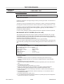
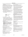
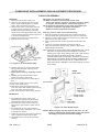
HIGH VOLTAGE COMPONENTS REMOVAL
(HIGH VOLTAGE CAPACITOR AND HIGH VOLTAGE RECTIFIER ASSEMBLY)
To remove the components, proceed as
follows.
1. CARRY OUT 3D CHECKS
2. Disconnect the filament lead of the high
voltage transformer secondary wire from
high voltage capacitor.
3. Disconnect the high voltage wire B from the
magnetron.
4. Remove one (1) screw holding earth side
terminal of high voltage rectifier assembly.
5. Remove one (1) screw holding fan duct to
the oven cavity rear plate.
6. Remove one (1) screw holding the capacitor
from the oven cavity rear plate.
7. Release the capacitor holder from the fan
duct.
8. Remove the high voltage capacitor from the capacitor
holder.
9. Disconnect the high voltage wire B and the high voltage
rectifier assembly from the high voltage capacitor.
10. Disconnect the high voltage rectifier assembly from
the high voltage wire B.
11. Now, the high voltage rectifier assembly and the high
voltage capacitor should be free.
CAUTION:
WHEN REPLACING HIGH VOLTAGE
RECTIFIER ASSEMBLY, ENSURE THAT
THE CATHODE (EARTH) CONNECTION IS
SECURELY FIXED TO THE CAPACITOR.
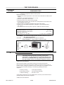
HIGH VOLTAGE TRANSFORMER REMOVAL
1. CARRY OUT 3D CHECKS
2. Disconnect the filament leads of the power
transformer from high voltage capacitor and the
magnetron.
3. Disconnect the H.V. secondary wire from the
power transformer.
4. Disconnect the leads of the transformer
primary.
5. Remove the two (2) screws holding the transformer to
base plate.
6. Remove the transformer from the base plate by sliding
it away from the oven cavity and lifting it.
7. Now, the power transformer is free.
MAGNETRON REMOVAL
1. CARRY OUT 3D CHECKS.
2. Disconnect the H.V. wire B and filament lead of
the transformer from the magnetron.
3. Remove the one (1) screw holding the chassis
support to the magnetron
4. Move the air intake duct to left.
5. Carefully remove three (3) screws holding the
magnetron to the waveguide. When removing
the screws hold the magnetron to prevent it from
falling.
6. Remove the magnetron from the waveguide with
care so the magnetron antenna is not hit by any
metal object around the antenna.
CAUTION: WHEN REPLACING THE MAGNETRON,
BE SURE THE R.F. GASKET IS IN PLACE AND
THE MAGNETRON MOUNTING SCREWS ARE
TIGHTENED SECURELY.
ENSURE THE MAGNETRON WIRING IS
REFITTED IN ACCORDANCE WITH THE
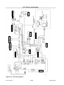
PICTORIAL DIAGRAM ON PAGE 33 (FA AND F).
CONTROL PANEL ASSEMBLY REMOVAL
1. CARRY OUT 3D CHECKS.
2. Disconnect the main wire harness from the
control panel.
3. Remove the one (1) screw holding the control
panel to the oven cavity.
4. Lift the control panel assembly and pull it forward. Now,
the control panel assembly is free.
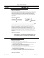
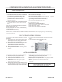
TURNTABLE MOTOR REMOVAL
1. Disconnect the oven from the power supply.
2. Remove the turntable motor cover by snipping
off the material in four corners.
3. Where the corners have been snipped off bent
corner areas flat. No sharp edge must be
evident after removal of turntable motor cover.
4. Disconnect the wire leads from the turntable motor
and remove the one (1) screw holding the
turntable motor.
5. Turntable motor is now free.
6. After replacement use one (1) screw to fit the
turntable motor cover.(code 5028 05 76-00/5).
SOI 03.06 FV
29/38
599 36 78-45