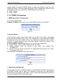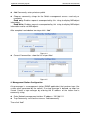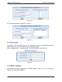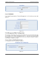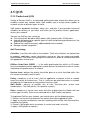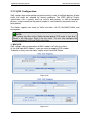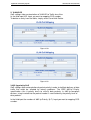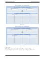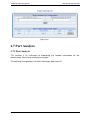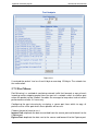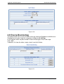
1
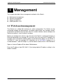
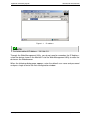
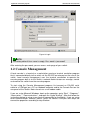
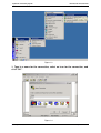
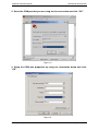
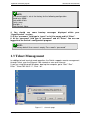
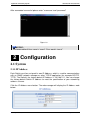
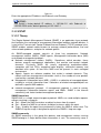
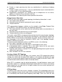
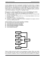
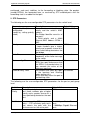
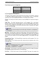
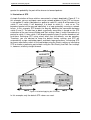
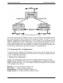
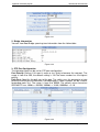
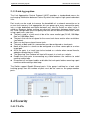
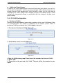
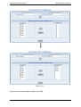
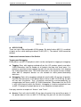
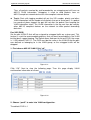
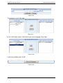
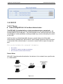
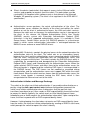
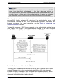
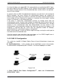
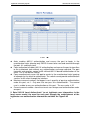
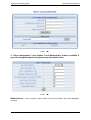
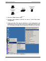
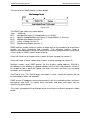
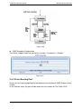
Signamax Connectivity System 065-7708, 065-7728, 065-7764 Signamax Connectivity Systems Management Switch Model: 065-7708 065-7728 065-7764 User's Guide www.signamax-us.com www.signamax-eu.com Signamax Connectivity System 065-7708, 065-7728, 065-7764 1 Management This chapter describes three management methods of the Switch. Web-based management Console management Telnet management SNMP provides v1/v2 1.1 Web-based management The Switch has a Web GUI interface for switch configuration. The Switch can be configured through the Web browser. A network administrator can manage, control, and monitor the Switch from the local LAN. This section indicates how to configure the Switch to enable its smart functions including: Before you configure this device, note that when the Switch is configured through an Ethernet connection, the manager PC must be set on the same the IP network. For example, when the default network address of the default IP address of the Switch is 192.168.2.11, then the manager PC should be set at 192.168.2.x (where x is a number between 1 and 254 except 11), and the default subnet mask is 255.255.255.0. Open an Internet Explorer 5.0 or above Web browser. Enter the IP address http://192.168.2.11 (the factory-default IP address setting) in the address location. www.signamax-us.com www.signamax-eu.com Signamax Connectivity System 065-7708, 065-7728, 065-7764 Figure 1-1 IP address NOTE: The factory-default IP Address : 192.168.2.11 Through the Web Management Utility, you do not need to remember the IP Address; select the device shown in the Monitor List of the Web Management Utility to settle the device on the Web browser. When the following dialog page appears, enter the default user name and password and press Login to enter the main configuration window. www.signamax-us.com www.signamax-eu.com Signamax Connectivity System 065-7708, 065-7728, 065-7764 Figure1-2 Login NOTE: The factory-default User name is empty. Pass word is “password” After entering the password, you can access main page of your switch. 1.2 Console Management A local console is a terminal or a workstation running a terminal emulation program that is connected directly to the switch via the RS-232 console port on the rear of the switch. Local console management uses the terminal connection to operate the console program built-in to the Switch a network Administrator can manage, control and monitor the switch from the console program. To start using the Console Management program, first connect an EIA-232 serial cable to a COM port on a PC or notebook computer and to the Console Port on the rear panel of the Switch. Note: do not use a null modem cable. If you are using Microsoft Windows, boot up the computer, go to “Start” -“Programs”“Accessories”, -“Communications”, and open the “HyperTerminal”. After that follow the instructions below to setup a new terminal connection for the Switch. If you are using other communication software, please select the correct COM port and setup the connection properties according to step 3 below. www.signamax-us.com www.signamax-eu.com Signamax Connectivity System 065-7708, 065-7728, 065-7764 Figure 1-3 1. Type in a name for the connection, select an icon for the connection, and click “OK”. Figure 1-4 www.signamax-us.com www.signamax-eu.com Signamax Connectivity System 065-7708, 065-7728, 065-7764 2. Select the COM port that you are using for this connection and click “OK”. Figure 1-5 3. Setup the COM port properties by using the information below and click “OK”. Figure1-6 www.signamax-us.com www.signamax-eu.com Signamax Connectivity System 065-7708, 065-7728, 065-7764 NOTE: The console port is set at the factory for the following configuration: Baud rate: 9,600 Data width: 8 bits Parity: none Stop bits: 1 Flow Control: None 4. You should see some boot-up messages displayed within your “HyperTerminal” session. 5. At the “username” field type in “guest” or let it be empty and hit “Enter”. 6. At the “password” field type in “password” and hit “Enter”. You are now logged into the Switch’s configuration program. NOTE: The factory-default User name is empty. Pass word is “password” 1.3 Telnet Management In addition to local terminal mode operation, the Switch supports remote management through Telnet, over the Ethernet LAN network or even over internet. If you are using Microsoft Windows, boot up the computer, go to “Start”-“Run”. Enter ” Telnet 192.168.2.11”, Click “ ok”. Figure 1-7 www.signamax-us.com the main page www.signamax-eu.com Signamax Connectivity System 065-7708, 065-7728, 065-7764 After connected successful please enter” username “and “password” Figure 1-8 NOTICE: The factory-default User name is “guest”. Pass word is “guest” 2 Configuration 2.1 System 2.1.1 IP Address Each Switch must be assigned its own IP Address, which is used for communication with an SNMP network manager or other TCP/IP application (for example BOOTP, TFTP). The Switch’s the factory-default IP Address is 192.168.2.11. You can change the factory-default Switch IP address to meet the specification of your networking address scheme. Click the IP Address menu button. The web manager will display the IP Address web below. www.signamax-us.com www.signamax-eu.com Signamax Connectivity System 065-7708, 065-7728, 065-7764 Figure 2-1 Enter the appropriate IP Address and Submask and Gateway. NOTICE: The Switch’s factory-default IP address is 192.168.2.11 with Submask of 255.255.255.0 and a default gateway of 192.168.2.1 2.1.2 SNMP 2.1.2.1 Theory The Simple Network Management Protocol (SNMP) is an application layer protocol that facilitates the exchange of management information between network devices. It is part of the Transmission Control Protocol/Internet Protocol (TCP/IP) protocol suite. SNMP enables network administrators to manage network performance, find and solve network problems, and plan for network growth. An SNMP-managed network consists of three key components: Network management stations (NMSs), SNMP agents, Management information base (MIB) and network-management protocol: Network management stations (NMSs) : Sometimes called consoles, these devices execute management applications that monitor and control network elements. Physically, NMSs are usually engineering workstation-caliber computers with fast CPUs, megapixel color displays, substantial memory, and abundant disk space. At least one NMS must be present in each managed environment. Agents:Agents are software modules that reside in network elements. They collect and store management information such as the number of error packets received by a network element. Management information base (MIB):A MIB is a collection of managed objects residing in a virtual information store. Collections of related managed objects are defined in specific MIB modules. network-management protocol : A management protocol is used to convey management information between agents and NMSs. SNMP is the Internet community's de facto standard management protocol. SNMP Operations SNMP itself is a simple request/response protocol. NMSs can send multiple requests without receiving a response. Get -- Allows the NMS to retrieve an object instance from the agent. Set -- Allows the NMS to set values for object instances within an agent. Trap -- Used by the agent to asynchronously inform the NMS of some event. The SNMPv2 trap message is designed to replace the SNMPv1 trap message. SNMP community An SNMP community is the group that devices and management stations running SNMP belong to. It helps define where information is sent. The community name is www.signamax-us.com www.signamax-eu.com Signamax Connectivity System 065-7708, 065-7728, 065-7764 used to identify the group. A SNMP device or agent may belong to more than one SNMP community. It will not respond to requests from management stations that do not belong to one of its communities. SNMP default communities are: Write = private Read = public 2.1.2.2 SNMP Configuration 1. SNMP Agent Status Configuration First turn on SNMP Agent. Enabled / Disabled: To turn on or turn off the SNMP function on the Switch. Figure 2-2 2. System Options Used to define a logical name to the switch, the location of the switch, and contact person for administration of the switch. This information is used in Enterprise SNMP management, where the network can be very widespread, potentially even in other countries. To know where the unit is physically located, and who to contact in the event of a problem is critical. In “system options” table configuration consists of three key components: System Name: Enter a name to be used for the switch. System Location: Enter the location of the switch. For example enter “TONGMEI17F” Contact: Enter the name of the person or organization that maintains the switch. For example enter “Test” After complete hereinbefore three steps click “ok”. Figure 2-3 3. Community Configuration Use this table to create an SNMP community string to define the relationship between the SNMP manager and an agent. The community string acts like a password to permit access to the agent on the Switch. One or more of the following characteristics can be associated with the community string: www.signamax-us.com www.signamax-eu.com Signamax Connectivity System 065-7708, 065-7728, 065-7764 Add Community: enter private or public Chooses community strings for the Switch management access: read only or read/write Read only: Enables requests accompanied by this string to display MIB-object information. Read/Write: Enables requests accompanied by this string to display MIB-object information and to set MIB objects. After complete hereinbefore two steps click “ Add”. Figure 2-4 Current Communities: show the list in input field Figure 2-5 4. Management Station Configuration A trap manager is a management station (SNMP application) that receives traps (the system alerts generated by the switch). If no trap manager is defined, no traps are issued. Create a trap manager by entering the IP address of the station and a community string. Enter Network management stations IP address: 192.168.2.11 Trap Community: must be the same as “Add community” Then click “Add” www.signamax-us.com www.signamax-eu.com Signamax Connectivity System 065-7708, 065-7728, 065-7764 Figure 2-6 IN “Current Management Stations” show list Figure 2-7 2.1.3 Password Password is the invaluable tool for the manager to secure the Web Management Switch. You can use this function to change the password. Enter “old password “, “new password”, “confirm password” and click “ok”. Figure 2-8 2.1.4 MAC Address Each Switch must be assigned its own MAC Address. You can use this function to modify the Switch MAC address. www.signamax-us.com www.signamax-eu.com Signamax Connectivity System 065-7708, 065-7728, 065-7764 Figure 2-9 2.1.5 CONSOLE If you forget the parameter of Console Management .In this function you can look about all. Figure 2-10 2.1.6 Management Host Configuration This function is based upon the security of the Switch. If turn on this function then only one IP address of in “Enter Management Host IP “ input field can land the Web management .If turn off this function then all host of the same the network IP address as the Switch ‘IP address can do it. Turn on: Choose “startup Management Host”. In ”Management Host IP” field input IP address. Figure 2-11 www.signamax-us.com www.signamax-eu.com Signamax Connectivity System 065-7708, 065-7728, 065-7764 2.1.7 System Upgrade This function allows the administrator to perform a WEB firmware update. Click “Browse” to choose firmware. You must wait for some seconds. Upgrade successful will be show in “Update Status” Figure 2-12 CAUTION: In course of System Upgrade, Please don’t touch The Switch Power. 2.1.8 Saving Parameters This operation will save all your parameters on the switch. After reboot the switch, all the parameters are still valid. If don’t do it the parameters will lose after reboot system. Figure 2-13 2.1.9 Parameters Backup & Recovery Backup: The backup tools help you to backup the current setting of the Switch. Once you need to backup the setting, press the “Backup the system's parameters” button to save the setting. Recovery: To restore a current setting file to the device, you must specify the backup file and press the “Browse” button to process the setting of the recorded file. www.signamax-us.com www.signamax-eu.com Signamax Connectivity System 065-7708, 065-7728, 065-7764 Figure 2-14 2.1.10 Load Default This operation helps you to reset the device back to the default setting from the factory. Be aware that the entire configuration will be reset, the IP address will be retrieved .The default IP address of 192.168.2.11 will be used. Figure 2-15 CAUTION: This operation will result in all the parameters losing. Except for urgency please cautioning! 2.1.11 Reboot Reboot the system. Figure 2-16 www.signamax-us.com www.signamax-eu.com Signamax Connectivity System 065-7708, 065-7728, 065-7764 2.2 Port Management 2.2.1 Port Configuration This page displays the current status of every port. It will display the user’s selection for each port followed by the actual discovered settings. Management Status: Display port status: Enable or Disable, Disable indicates port is off. Link Status: Down indicates “No Link”, up indicates “Link”. Speed: Used to set the port speed to either 100Mbps or 10Mbps on Port1~Port48. Duplex: Displays full-duplex or half-duplex mode. Flow Control: Display Flow status of port: Enable or Disable, Disable indicates Flow control is off. Auto: Display which mode the port is auto-negotiated Config: (configured) Displays the state defined by the user. Atual: (actual) Displays the negotiation result. Figure 2-17 2.2.2 Port Statistics The Port Statistics page provides a view of the current status of every port on the Switch. Pressing the “Reset” button will reset all port counters to zero. 2.2.3 Port Band Restrict The function provides for the administrator In-Band Restrict and Out-Band Restrict of every port on the Switch. Input the range from 64Kbps to 8000Kbps. www.signamax-us.com www.signamax-eu.com Signamax Connectivity System 065-7708, 065-7728, 065-7764 Figure 2-18 2.3 Redundancy 2.3.1 Spanning Tree 1. Spanning Tree Protocol The IEEE 802.1D Spanning Tree Protocol allows for the blocking of links between switches that form loops within the network. When multiple links between switches are detected, a primary link is established. Duplicated links are blocked from use and become standby links. The protocol allows for the duplicate links to be used in the event of a failure of the primary link. Once the Spanning Tree Protocol is configured and enabled, primary links are established and duplicated links are blocked automatically. The reactivation of the blocked links (at the time of a primary link failure) is also accomplished automatically without operator intervention. This automatic network reconfiguration provides maximum uptime to network users. However, the concepts of the Spanning Tree Algorithm and protocol are a complicated and complex subject and must be fully researched and understood. It is possible to cause serious degradation of the performance of the network if the Spanning Tree is incorrectly configured. Please read the following before making any changes from the default values. The Switch STP performs the following functions: www.signamax-us.com www.signamax-eu.com Signamax Connectivity System 065-7708, 065-7728, 065-7764 Creates a single spanning tree from any combination of switching or bridging elements. Creates multiple spanning trees – from any combination of ports contained within a single switch, in user specified groups. Automatically reconfigures the spanning tree to compensate for the failure, addition, or removal of any element in the tree. Reconfigures the spanning tree without operator intervention. Bridge Protocol Data Units For STP to arrive at a stable network topology, the following information is used: The unique switch identifier The path cost to the root associated with each switch port The port identifier STP communicates between switches on the network using Bridge Protocol Data Units (BPDUs). Each BPDU contains the following information: The unique identifier of the switch that the transmitting switch currently believes is the root switch The path cost to the root from the transmitting port The port identifier of the transmitting port The switch sends BPDUs to communicate and construct the spanning-tree topology. All switches connected to the LAN on which the packet is transmitted will receive the BPDU. BPDUs are not directly forwarded by the switch, but the receiving switch uses the information in the frame to calculate a BPDU, and, if the topology changes, initiates a BPDU transmission. The communication between switches via BPDUs results in the following: One switch is elected as the root switch The shortest distance to the root switch is calculated for each switch A designated switch is selected. This is the switch closest to the root switch through which packets will be forwarded to the root. A port for each switch is selected. This is the port providing the best path from the switch to the root switch. P orts included in the STP are selected. Creating a Stable STP Topology To make the fastest link the root port. If all switches have STP enabled with default settings, the switch with the lowest MAC address in the network will become the root switch. By increasing the priority (lowering the priority number) of the best switch, STP can be forced to select the best switch as the root switch. When STP is enabled using the default parameters, the path between source and destination stations in a switched network might not be ideal. For instance, connecting higher-speed links to a port that has a higher number than the current root port can cause a root-port change. STP Port States The BPDUs take some time to pass through a network. This propagation delay can result in topology changes where a port that transitioned directly from a Blocking state to a Forwarding state could create temporary data loops. Ports must wait for new www.signamax-us.com www.signamax-eu.com Signamax Connectivity System 065-7708, 065-7728, 065-7764 network topology information to propagate throughout the network before starting to forward packets. They must also wait for the packet lifetime to expire for BPDU packets that were forwarded based on the old topology. The forward delay timer is used to allow the network topology to stabilize after a topology change. In addition, STP specifies a series of states a port must transition through to further ensure that a stable network topology is created after a topology change. Each port on a switch using STP exists is in one of the following five states: Blocking – the port is blocked from forwarding or receiving packets Listening – the port is waiting to receive BPDU packets that may tell the port to go back to the blocking state L earning – the port is adding addresses to its forwarding database, but not yet forwarding packets Forwarding – the port is forwarding packets Disabled – the port only responds to network management messages and must return to the blocking state first A port transitions from one state to another as follows: From initialization (switch boot) to blocking From blocking to listening or to disabled From listening to learning or to disabled From learning to forwarding or to disabled From forwarding to disabled From disabled to blocking Switch boot Blocking Listening Disabled Learning Forwarding Figure 5-20 STP Port State Transitions You can modify each port state by using management software. When you enable STP, every port on every switch in the network goes through the blocking state and then transitions through the states of listening and learning at power up. If properly www.signamax-us.com www.signamax-eu.com Signamax Connectivity System 065-7708, 065-7728, 065-7764 configured, each port stabilizes to the forwarding or blocking state. No packets (except BPDUs) are forwarded from, or received by, STP enabled ports until the forwarding state is enabled for that port. 2. STP Parameters The following are the user-configurable STP parameters for the switch level: Parameter Bridge Identifier(Not user configurable except by setting priority below) Priority Hello Time Maximum Age Timer Forward Delay Timer Description A combination of the User-set priority and the switch’s MAC address. The Bridge Identifier consists of two parts: a 16-bit priority and a 48-bit Ethernet MAC address 32768 + MAC A relative priority for each switch – lower numbers give a higher priority and a greater chance of a given switch being elected as the root bridge The length of time between broadcasts of the hello message by the switch Measures the age of a received BPDU for a port and ensures that the BPDU is discarded when its age exceeds the value of the maximum age timer. The amount time spent by a port in the learning and listening states waiting for a BPDU that may return the port to the blocking state. Default Value 32768 + MAC 32768 2 seconds 20 seconds 15 seconds The following are the user-configurable STP parameters for the port or port group level: Variable Port Priority Description Default Value A relative priority for each 32768 port –lower numbers give a higher priority and a greater chance of a given port being elected as the root port Port Cost A value used by STP to evaluate paths – STP calculates path costs and selects the path with the minimum cost as the active path www.signamax-us.com 19-100Mbps Fast Ethernet ports 4-1000Mbps Gigabit Ethernet ports www.signamax-eu.com Signamax Connectivity System 065-7708, 065-7728, 065-7764 Default Spanning-Tree Configuration Feature Enable state Port priority Port cost Bridge Priority Default Value STP enabled for all ports 128 19 32,768 User-Changeable STA Parameters The Switch’s factory default setting should cover the majority of installations. However, it is advisable to keep the default settings as set at the factory; unless, it is absolutely necessary. The user changeable parameters in the Switch are as follows: Priority – A Priority for the switch can be set from 0 to 65535. 0 is equal to the highest Priority. Hello Time – The Hello Time can be from 1 to 10 seconds. This is the interval between two transmissions of BPDU packets sent by the Root Bridge to tell all other Switches that it is indeed the Root Bridge. If you set a Hello Time for your Switch, and it is not the Root Bridge, the set Hello Time will be used if and when your Switch becomes the Root Bridge. NOTICE: The Hello Time cannot be longer than the Max. Age. Otherwise, a configuration error will occur. Max. Age – The Max Age can be from 6 to 40 seconds. At the end of the Max Age, if a BPDU has still not been received from the Root Bridge, your Switch will start sending its own BPDU to all other Switches for permission to become the Root Bridge. If it turns out that your Switch has the lowest Bridge Identifier, it will become the Root Bridge. Forward Delay Timer – The Forward Delay can be from 4 to 30 seconds. This is the time any port on the Switch spends in the listening state while moving from the blocking state to the forwarding state. NOTICE: Observe the following formulas when setting the above parameters: Max. Age _ 2 x (Forward Delay - 1 second) Max. Age _ 2 x (Hello Time + 1 second) Port Priority – A Port Priority can be from 0 to 255. The lower the number, the greater the probability the port will be chosen as the Root Port. Port Cost – A Port Cost can be set from 0 to 65535. The lower the number, the www.signamax-us.com www.signamax-eu.com Signamax Connectivity System 065-7708, 065-7728, 065-7764 greater the probability the port will be chosen to forward packets. 3. Illustration of STP A simple illustration of three switches connected in a loop is depicted in Figure 5-7. In this example, you can anticipate some major network problems if the STP assistance is not applied. If switch A broadcasts a packet to switch B, switch B will broadcast it to switch C, and switch C will broadcast it to back to switch A ... and so on. The broadcast packet will be passed indefinitely in a loop, potentially causing a network failure. In this example, STP breaks the loop by blocking the connection between switch B and C. The decision to block a particular connection is based on the STP calculation of the most current Bridge and Port settings. Now, if switch A broadcasts a packet to switch C, then switch C will drop the packet at port 2 and the broadcast will end there. Setting-up STP using values other than the defaults, can be complex. Therefore, you are advised to keep the default factory settings and STP will automatically assign root bridges/ports and block loop connections. Influencing STP to choose a particular switch as the root bridge using the Priority setting, or influencing STP to choose a particular port to block using the Port Priority and Port Cost settings is, however, relatively straight forward. Figure 2-19 before Applying the STA Rules In this example, only the default STP values are used. www.signamax-us.com www.signamax-eu.com Signamax Connectivity System 065-7708, 065-7728, 065-7764 Figure 2-20 After Applying the STA Rules The switch with the lowest Bridge ID (switch C) was elected the root bridge, and the ports were selected to give a high port cost between switches B and C. The two (optional) Gigabit ports (default port cost = 4) on switch A are connected to one (optional) Gigabit port on both switch B and C. The redundant link between switch B and C is deliberately chosen as a 100 Mbps Fast Ethernet link (default port cost = 19). Gigabit ports could be used, but the port cost should be increased from the default to ensure that the link between switch B and switch C is the blocked link. 2.3.2 Spanning Tree Configuration The Spanning Tree Protocol (STP) operates on two levels: on the switch level, the settings are globally implemented. On the port level, the settings are implemented on a. per user-defined Group of ports. 1. Spanning Tree Configuration Configure the following parameters and click the Apply button to implement them: Status: Default<Disabled>.This field can be toggled between Enabled and Disabled using the pulld own menu. This will enable or disable the Spanning Tree Protocol (STP), globally, for the Switch. Max Age: (6 - 40 sec) the default setting is 20 Hello Time: (1 - 10sec) the default setting is 2 Forward Delay: (4 -30 sec) the default setting is 15 Bridge Priority: (0 - 61440) the default setting is 32768 www.signamax-us.com www.signamax-eu.com Signamax Connectivity System 065-7708, 065-7728, 065-7764 Figure 2-21 2. Bridge Information You can view Root Bridge spanning tree information from the follow table. Figure 2-22 3. STP Port Configuration The following fields can be set for STP port configuration: Port Priority: Defines if this port is more or less likely to become the root port. The range is from 0 to 255, the default setting is 128.The lower number has the highest priority. Path Cost: Specifies the path cost of the port. The switch uses this parameter to help determine which port will become a forwarding port. Lower numbers will be used as forwarding ports first. The range is from 0 to 65535. The default values based on IEEE802.1D are: 10Mb/s = 50-600, 100Mb/s = 10-60, 1000Mb/s = 3-10 Figure 2-23 www.signamax-us.com www.signamax-eu.com Signamax Connectivity System 065-7708, 065-7728, 065-7764 2.3.3 Link Aggregation The Link Aggregation Control Protocol (LACP) provides a standardized means for exchanging information between Partner Systems that require high speed redundant links. Port trunks can be used to increase the bandwidth of a network connection or to ensure fault recovery. Link aggregation lets you group up to many consecutive ports into a single dedicated connection between any two the Switch or other Layer 2 switches. However, before making any physical connections between devices, use the Trunk Configuration menu to specify the trunk on the devices at both ends. When using a port trunk, note that: The ports used in a trunk must all be of the same media type (RJ-45, 100 Mbps fiber, or 1000 Mbps fiber). The ports that can be assigned to the same trunk have certain other restrictions (see below). Ports can only be assigned to one trunk. The ports at both ends of a connection must be configured as trunk ports. None of the ports in a trunk can be configured as a mirror source port or a mirror target port. All of the ports in a trunk have to be treated as a whole when moved from/to, added or deleted from a VLAN. The Spanning Tree Protocol will treat all the ports in a trunk as a whole. Enable the trunk prior to connecting any cable between the switches to avoid creating a data loop. Disconnect all trunk port cables or disable the trunk ports before removing a port trunk to avoid creating a data loop. The Switch support Gigabit Ethernet ports. If the group is defined as a local static trunking group, then the number of ports must be the same as the group member ports. Figure 2-24 2.4 Security 2.4.1 VLANs www.signamax-us.com www.signamax-eu.com Signamax Connectivity System 065-7708, 065-7728, 065-7764 2.4.1.1 Theory Understanding IEEE 802.1p Priority Priority tagging is a function defined by the IEEE 802.1p standard designed to provide a means of managing traffic on a network where many different types of data may be transmitted simultaneously. It is intended to alleviate problems associated with the delivery of time critical data over congested networks. The quality of applications that are dependent on such time critical data, such as video conferencing, can be severely and adversely affected by even very small delays in transmission. Network devices that are in compliance with the IEEE 802.1p standard have the ability to recognize the priority level of data packets. These devices can also assign a priority label or tag to packets. Compliant devices can also strip priority tags from packets. This priority tag determines the packet's degree of expeditiousness and determines the queue to which it will be assigned. Priority tags are given values from 0 to 7 with 0 being assigned to the lowest priority data and 7 assigned to the highest. The highest priority tag 7 is generally only used for data associated with video or audio applications, which are sensitive to even slight delays, or for data from specified end users whose data transmissions warrant special consideration. The Switch allows you to further tailor how priority tagged data packets are handled on your network. Using queues to manage priority tagged data allows you to specify its relative priority to suit the needs of your network. There may be circumstances where it would be advantageous to group two or more differently tagged packets into the same queue. Generally, however, it is recommended that the highest priority queue, Queue 1, be reserved for data packets with a priority value of 7. Packets that have not been given any priority value are placed in Queue 0 and thus given the lowest priority for delivery. A weighted round robin system is employed on the Switch to determine the rate at which the queues are emptied of packets. The ratio used for clearing the queues is 4:1. This means that the highest priority queue, Queue 1, will clear 4 packets for every 1 packet cleared from Queue 0. Remember, the priority queue settings on the Switch are for all ports, and all devices connected to the Switch will be affected. This priority queuing system will be especially beneficial if your network employs switches with the capability of assigning priority tags. VLANs Description A Virtual Local Area Network (VLAN) is a network topology configured according to a logical scheme rather than the physical layout. VLAN can be used to combine any collection of LAN segments into an autonomous user group that appears as a single LAN. VLAN also logically segment the network into different broadcast domains so that packets are forwarded only between ports within the VLAN. Typically, a VLAN corresponds to a particular subnet, although not necessarily. www.signamax-us.com www.signamax-eu.com Signamax Connectivity System 065-7708, 065-7728, 065-7764 VLAN can enhance performance by conserving bandwidth, and improve security by limiting traffic to specific domains. A VLAN is a collection of end nodes grouped by logic instead of physical location. End nodes that frequently communicate with each other are assigned to the same VLAN, regardless of where they are physically on the network. Logically, a VLAN can be equated to a broadcast domain, because broadcast packets are forwarded to only members of the VLAN on which the broadcast was initiated. NOTICE: 1. No matter what basis is used to uniquely identify end nodes and assign these nodes VLAN membership, packets cannot cross VLAN without a network device performing a routing function between the VLAN. 2. The Switch supports Port-based VLAN and IEEE 802.1Q VLAN. The port untagging function can be used to remove the 802.1 tag from packet headers to maintain compatibility with devices that are tag-unaware. 3. The Switch's default is to assign all ports to a single 802.1Q VLAN named DEFAULT_VLAN. As new VLA N is created, the member ports assigned to the new VLAN will be removed from the DEFAULT_ VLAN port member list. The DEFAULT_VLAN has a VID = 1. Port-based VLANs Port-based VLAN limit traffic that flows into and out of switch ports. Thus, all devices connected to a port are members of the VLAN(s) the port belongs to, whether there is a single computer directly connected to a switch, or an entire department. On port-based VLAN.NIC do not need to be able to identify 802.1Q tags in packet headers. NIC send and receive normal Ethernet packets. If the packet's destination lies on the same segment, communications take place using normal Ethernet protocols. Even though this is always the case, when the destination for a packet lies on another switch port, VLAN considerations come into play to decide if the packet is dropped by the Switch or delivered. IEEE 802.1Q VLANs IEEE 802.1Q (tagged) VLAN are implemented on the Switch. 802.1Q VLAN require tagging, which enables them to span the entire network (assuming all switches on the network are IEEE 802.1Q-compliant). VLAN allow a network to be segmented in order to reduce the size of broadcast domains. All packets entering a VLAN will only be forwarded to the stations (over IEEE 802.1Q enabled switches) that are members of that VLAN, and this includes broadcast, multicast and unicast packets from unknown sources. VLAN can also provide a level of security to your network. IEEE 802.1Q VLAN will only deliver packets between stations that are members of the VLAN. Any port can be configured as either tagging or untagging. The untagging feature of IEEE 802.1Q VLAN allows VLAN to work with legacy switches that don't recognize VLAN tags in packet headers. The tagging feature allows VLAN to span multiple 802.1Q-compliant www.signamax-us.com www.signamax-eu.com Signamax Connectivity System 065-7708, 065-7728, 065-7764 switches through a single physical connection and allows Spanning Tree to be enabled on all ports and work normally. Any port can be configured as either tagging or untagging. The untagging feature of IEEE 802.1Q VLAN allow VLAN to work with legacy switches that don’t recognize VLAN tags in packet headers. The tagging feature allows VLAN to span multiple 802.1Q-compliant switches through a single physical connection and allows Spanning Tree to be enabled on all ports and work normally. Some relevant terms: Tagging - The act of putting 802.1Q VLAN information into the header of a packet. Untagging - The act of stripping 802.1Q VLAN information out of the packet header. 802.1Q VLAN Tags The figure below shows the 802.1Q VLAN tag. There are four additional octets inserted after the source MAC address. Their presence is indicated by a value of 0x8100 in the Ether Type field. When a packet's Ether Type field is equal to 0x8100, the packet carries the IEEE 802.1Q/802.1p tag. The tag is contained in the following two octets and consists of 3 bits of user priority, 1 bit of Canonical Format Identifier (CFI - used for encapsulating Token Ring packets so they can be carried across Ethernet backbones), and 12 bits of VLAN ID (VID). The 3 bits of user priority are used by 802.1p. The VID is the VLAN identifier and is used by the 802.1Q standard. Because the VID is 12 bits long, 4094 unique VLAN can be identified. The tag is inserted into the packet header making the entire packet longer by 4 octets. All of the information originally contained in the packet is retained. Figure 2-25 The Ether Type and VLAN ID are inserted after the MAC source address, but before the original Ether Type/Length or Logical Link Control. Because the packet is now a bit longer than it was originally, the Cyclic Redundancy Check (CRC) must be recalculated. www.signamax-us.com www.signamax-eu.com Signamax Connectivity System 065-7708, 065-7728, 065-7764 Figure 2-26 Port VLAN ID Packets that are tagged (are carrying the 802.1Q VID information) can be transmitted from one 802.1Q compliant network device to another with the VLAN information intact. This allows 802.1Q VLAN to span network devices (and indeed, the entire network – if all network devices are 802.1Q compliant). Every physical port on a switch has a PVID. 802.1Q ports are also assigned a PVID, for use within the switch. If no VLAN are defined on the switch, all ports are then assigned to a default VLAN with a PVID equal to 1. Untagged packets are assigned the PVID of the port on which they were received. Forwarding decisions are based upon this PVID, in so far as VLAN are concerned. Tagged packets are forwarded according to the VID contained within the tag. Tagged packets are also assigned a PVID, but the PVID is not used to make packet forwarding decisions, the VID is. Tag-aware switches must keep a table to relate PVID within the switch to VID on the network. The switch will compare the VID of a packet to be transmitted to the VID of the port that is to transmit the packet. If the two VID are different the switch will drop the packet. Because of the existence of the PVID for untagged packets and the VID for tagged packets, tag-aware and tag-unaware network devices can coexist on the same network. A switch port can have only one PVID, but can have as many VID as the switch has memory in its VLAN table to store them. Because some devices on a network may be tag-unaware, a decision must be made at each port on a tag-aware device before packets are transmitted – should the packet to be transmitted have a tag or not? If the transmitting port is connected to a tag-unaware device, the packet should be untagged. If the transmitting port is connected to a tag-aware device, the packet should be tagged. Default VLANs The Switch initially configures one VLAN, VID = 1, called "default." The factory default setting assigns all ports on the Switch to the "default." As new VLAN are configured in Port-based mode, their respective member ports are removed from the "default." www.signamax-us.com www.signamax-eu.com Signamax Connectivity System 065-7708, 065-7728, 065-7764 VLANs and Trunk Groups In order to use VLAN segmentation in conjunction with port trunk groups, you can first set the port trunk group(s), and then you may configure VLAN settings. If you wish to change the port trunk grouping with VLAN already in place, you will not need to reconfigure the VLAN settings after changing the port trunk group settings. VLAN settings will automatically change in conjunction with the change of the port trunk group settings 2.4.1.2 VLAN Configuration Port-based VLANs Packets can only be broadcast among other members of the same VLAN group. Note all unselected ports are treated as belonging to the default system VLAN. If port-based VLAN are enabled, then VLAN-tagging is ignored. 1. First choose Port-based VLAN. Click “ok” Figure 2-27 2. Click Add to create a new VLAN group. Figure 2-28 3.Type the VLAN name, group ID and select the members for the new VLAN. 4. Click “Add”. 5. Then pitch on the port and click “Add” .The port will be the member for one VALN. www.signamax-us.com www.signamax-eu.com Signamax Connectivity System 065-7708, 065-7728, 065-7764 Figure 2-29 If you want to show or add or modify the VLAN. www.signamax-us.com www.signamax-eu.com Signamax Connectivity System 065-7708, 065-7728, 065-7764 Figure 2-30 802.1Q VLAN There are up to 256 configurable VLAN groups. By default when 802.1Q is enabled, all ports on the switch belong to default VLAN (VID 1). The default VLAN cannot be deleted. Understand nomenclature of the Switch Tagging and Untagging Every port on an 802.1Q compliant switch can be configured as tagging or untagging. Tagging: Ports with tagging enabled will put the VID number, priority and other VLAN information into the header of all packets that flow into those ports. If a packet has previously been tagged, the port will not alter the packet, thus keeping the VLAN information intact. The VLAN information in the tag can then be used by other 802.1Q compliant devices on the network to make packet-forwarding decisions. Untagging: Ports with untagging enabled will strip the 802.1Q tag from all packets that flow into those ports. If the packet doesn't have an 802.1Q VLAN tag, the port will not alter the packet. Thus, all packets received by and forwarded by an untagging port will have no 802.1Q VLAN information. (Remember that the PVID is only used internally within the Switch). Untagging is used to send packets from an 802.1Q-compliant network device to a non-compliant network device. Here pay attention to explain of “Access” and “Trunk”. Access: Ports will strip the 802.1Q tag from all packets that out of those ports. If the packet doesn’t have an 802.1Q VLAN tag, the port will not alter the packet. www.signamax-us.com www.signamax-eu.com Signamax Connectivity System 065-7708, 065-7728, 065-7764 Thus, all packets received by and forwarded by an untagging port will have no 802.1Q VLAN information. Untagging is used to send packets from an 802.1Q-compliant network device to a non-compliant network device. Trunk: Ports with tagging enabled will put the VID number, priority and other VLAN information into the header of all packets that out of those ports. If a packet has previously been tagged, the port will not alter the packet, thus keeping the VLAN information intact. The VLAN information in the tag can then be used by other 802.1Q compliant devices on the network to make packet forwarding decisions. Port VID (PVID) Set the port VLAN ID that will be assigned to untagged traffic on a given port. This feature is useful for accommodating devices that you want to participate in the VLAN but that don’t support tagging. The Switch allows each port to set one PVID, the range is 1~255, default PVID is 1. The PVID must be the same as the VLAN ID that the port was defined as belonging to in the VLAN group, or the untagged traffic will be dropped. 1. First choose 802.1Q VLAN. Click “ok” Figure 2-31 Click “OK”. Next to view the following page: Then this page display VALN configuration information of all port Figure 2-32 2. Choose “port2” to enter into VLAN configuration. The default PVID is 1 www.signamax-us.com www.signamax-eu.com Signamax Connectivity System 065-7708, 065-7728, 065-7764 Figure 2-33 Figure 2-34 3. Choose the type of link :Access or Trunking. Define PVID for port2 Figure 2-35 4. Trunk configuration: Port2 with tagging enabled will put the VID number, priority and other VLAN information into the header of all packets that out of it. Type a name for the new VLAN. Type a VID (between 2-4094). The default is 1.Clicd “Add”. www.signamax-us.com www.signamax-eu.com Signamax Connectivity System 065-7708, 065-7728, 065-7764 Figure 2-36 Then display in the VLAV table. Figure 2-37 In the VLAN table choose VLAN which you want to tagging. Click “Add” Figure 2-38 If you want to display one VLAN. Figure 2-39 www.signamax-us.com www.signamax-eu.com Signamax Connectivity System 065-7708, 065-7728, 065-7764 Figure 2-40 2.4.2 802.1X 2.4.2.1 Theory ● Understanding IEEE 802.1X Port-Based Authentication The IEEE 802.1X standard defines a client-server-based access control and authentication protocol that restricts unauthorized clients from connecting to a LAN through publicly accessible ports. The authentication server authenticates each client connected to a switch port before making available any services offered by the switch or the LAN. Until the client is authenticated, 802.1X access control allows only Extensible Authentication Protocol over LAN (EAPOL) traffic through the port to which the client is connected. After authentication is successful, normal traffic can pass through the port. This section includes this conceptual information: • • • Device Roles Authentication Initiation and Message Exchange Ports in Authorized and Unauthorized States Device Roles With 802.1X port-based authentication, the devices in the network have specific roles as shown below. Figure 2-41 www.signamax-us.com www.signamax-eu.com Signamax Connectivity System 065-7708, 065-7728, 065-7764 Client—the device (workstation) that requests access to the LAN and switch services and responds to requests from the switch. The workstation must be running 802.1X-compliant client software such as that offered in the Microsoft Windows XP operating system. (The client is the supplicant in the IEEE 802.1X specification.) Authentication server—performs the actual authentication of the client. The authentication server validates the identity of the client and notifies the switch whether or not the client is authorized to access the LAN and switch services. Because the switch acts as the proxy, the authentication service is transparent to the client. In this release, the Remote Authentication Dial-In User Service (RADIUS) security system with Extensible Authentication Protocol (EAP) extensions is the only supported authentication server; it is available in Cisco Secure Access Control Server version 3.0. RADIUS operates in a client/server model in which secure authentication information is exchanged between the RADIUS server and one or more RADIUS clients. Switch (802.1X device)—controls the physical access to the network based on the authentication status of the client. The switch acts as an intermediary (proxy) between the client and the authentication server, requesting identity information from the client, verifying that information with the authentication server, and relaying a response to the client. The switch includes the RADIUS client, which is responsible for encapsulating and decapsulating the Extensible Authentication Protocol (EAP) frames and interacting with the authentication server. When the switch receives EAPOL frames and relays them to the authentication server, the Ethernet header is stripped and the remaining EAP frame is re-encapsulated in the RADIUS format. The EAP frames are not modified or examined during encapsulation, and the authentication server must support EAP within the native frame format. When the switch receives frames from the authentication server, the server's frame header is removed, leaving the EAP frame, which is then encapsulated for Ethernet and sent to the client. Authentication Initiation and Message Exchange The switch or the client can initiate authentication. If you enable authentication on a port by using the dot1x port-control auto interface configuration command, the switch must initiate authentication when it determines that the port link state transitions from down to up. It then sends an EAP-request/identity frame to the client to request its identity (typically, the switch sends an initial identity/request frame followed by one or more requests for authentication information). Upon receipt of the frame, the client responds with an EAP-response/identity frame. However, if during bootup, the client does not receive an EAP-request/identity frame from the switch, the client can initiate authentication by sending an EAPOL-start frame, which prompts the switch to request the client's identity www.signamax-us.com www.signamax-eu.com Signamax Connectivity System 065-7708, 065-7728, 065-7764 NOTICE: If 802.1X is not enabled or supported on the network access device, any EAPOL frames from the client are dropped. If the client does not receive an EAP-request/identity frame after three attempts to start authentication, the client transmits frames as if the port is in the authorized state. A port in the authorized state effectively means that the client has been successfully authenticated. When the client supplies its identity, the switch begins its role as the intermediary, passing EAP frames between the client and the authentication server until authentication succeeds or fails. If the authentication succeeds, the switch port becomes authorized. For more information, see the "Ports in Authorized and Unauthorized States" section The specific exchange of EAP frames depends on the authentication method being used. “Figure 2-43” shows a message exchange initiated by the client using the One-Time-Password (OTP) authentication method with a RADIUS server. Figure 2-42 Ports in Authorized and Unauthorized States The switch port state determines whether or not the client is granted access to the network. The port starts in the unauthorized state. While in this state, the port disallows all ingress and egress traffic except for 802.1X protocol packets. When a client is successfully authenticated, the port transitions to the authorized state, allowing all traffic for the client to flow normally. www.signamax-us.com www.signamax-eu.com Signamax Connectivity System 065-7708, 065-7728, 065-7764 If a client that does not support 802.1X is connected to an unauthorized 802.1X port, the switch requests the client's identity. In this situation, the client does not respond to the request, the port remains in the unauthorized state, and the client is not granted access to the network. In contrast, when an 802.1X-enabled client connects to a port that is not running the 802.1X protocol, the client initiates the authentication process by sending the EAPOL-start frame. When no response is received, the client sends the request for a fixed number of times. Because no response is received, the client begins sending frames as if the port is in the authorized state If the client is successfully authenticated (receives an Accept frame from the authentication server), the port state changes to authorized, and all frames from the authenticated client are allowed through the port. If the authentication fails, the port remains in the unauthorized state, but authentication can be retried. If the authentication server cannot be reached, the switch can retransmit the request. If no response is received from the server after the specified number of attempts, authentication fails, and network access is not granted. When a client logs off, it sends an EAPOL-logoff message, causing the switch port to transition to the unauthorized state. If the link state of a port transitions from up to down, or if an EAPOL-logoff frame is received, the port returns to the unauthorized state. 2.4.2.2 802.1X Configuration This switch has two 802.1X Mode: Radius Server & Local Authenticate, choose one you need ● Local Authenticate — In this situation, do not need Radius server in the network, all authentication completed by 802.1x Switch,the normal topologies as below Figure 2-43 1. Enter “ 802.1X Port Status Configuration ” , there are 3“Authenticate authorization” states www.signamax-us.com www.signamax-eu.com Signamax Connectivity System 065-7708, 065-7728, 065-7764 Figure 2-44 Auto: enables 802.1X authentication and causes the port to begin in the unauthorized state, allowing only EAPOL frames to be sent and received through the port. It’s a default status Force authorized: disables 802.1X authentication and causes the port to transition to the authorized state without any authentication exchange required. The port transmits and receives normal traffic without 802.1X-based authentication of the client. This is the default setting. Force unauthorized: causes the port to remain in the unauthorized state, ignoring all attempts by the client to authenticate. The switch cannot provide authentication services to the client through the interface. Maximum account number: the biggest user's quantity of passing authentication under this port, set 1,Only one user can pass this authentication,The second user is unable to carry on authentication on this port。The max value is 32 Current account number: show the current user who passed authentication under one port. 2. Enter”802.1X Local Authenticate” to set legitimate user information: In the local server model, the need for each port through the establishment of the legitimate user authentication information available. As Figure2-45 ” www.signamax-us.com www.signamax-eu.com Signamax Connectivity System 065-7708, 065-7728, 065-7764 Figure 2-45 3. “Other configuration”: only choose “Local Authenticate” mode is available. If you not have good experiences please keep the default value. Figure 2-46 Radius Server — In this situation, need a Radius server in the network, the normal topologies as below www.signamax-us.com www.signamax-eu.com Signamax Connectivity System 065-7708, 065-7728, 065-7764 Figure 2-47 1. Select the “Radius Server” mode. 2. Configure ports attribute of 802.1X, the same as “802.1X Port Status Configuration”. 3. Create user data. That step are different of “Local Authenticate”, the establishment of the user data needs to be created on the Radius Server PC. For example, the Radius Server founded on Win2000 Server, and then: Figure 2-48 www.signamax-us.com www.signamax-eu.com Signamax Connectivity System 065-7708, 065-7728, 065-7764 Enter ” Active Directory Users and Computers”, create legal user data, the next, right-click a user what you created to enter properties, and what to be noticed: Figure 2-49 4. The last, run your 802.1X Client 2.4.3 MAC Address Binding This function is based upon for the switch security. When you add one MAC Address is bind with one port. it remains in the switch's address table, regardless of whether the device is physically connected to the switch. This saves the switch from having to re-learn a device's MAC address after it has been disconnected or powered-off from the network, and then reconnected at some time later. If the Network station connected with one port want to control the switch, The station’s MAC Address must be the same as one MAC Address In the MAC Address box, enter the MAC address that you want to bind and in the port box enter the corresponding port number. Click ”Add”. To Delete a MAC address Bind from the table, simply select it and click Delete. www.signamax-us.com www.signamax-eu.com Signamax Connectivity System 065-7708, 065-7728, 065-7764 Figure 2-50 Figure 2-51 2.4.4 MAC Address Filtering MAC address filtering allows the switch to drop unwanted traffic. Traffic is filtered based on the destination addresses. In the MAC Address box, enter the MAC address that you want to filter out. Click ”Add”. To Delete a MAC address entry from the filtering table, simply select it and click Delete. www.signamax-us.com www.signamax-eu.com Signamax Connectivity System 065-7708, 065-7728, 065-7764 Figure 2-52 Figure 2-53 2.4.5 MAC Address Learning For every port choose MAC Study’ status: Enable/Disable In the Port box enter the port number. Choose status. Click ”Ok” www.signamax-us.com www.signamax-eu.com Signamax Connectivity System 065-7708, 065-7728, 065-7764 Figure 2-54 2.4.6 MAC Address Aging Time The Aging Time affects the learning process of the Switch. Dynamic forwarding table entries, which are made up of the source and destination MAC addresses and their associated port numbers, are deleted from the table if they are not accessed within the aging time. The aging time can be from 30 to 1,000 seconds with a default value of 300 seconds. A very long aging time can result in dynamic forwarding table entries that are out-of-date or no longer exist. This may cause incorrect packet forward indecisions by the Switch. If the Aging Time is too short however, many entries may be aged out too soon. This will result in a high percentage of received packets whose source addresses cannot be found in the forwarding table, in which case the switch will broadcast the packet to all ports, negating many of the benefits of having a switch. Static forwarding entries are not affected by the aging time. Type the number of seconds that an inactive MAC address remains in the switch’s address table. The valid range is 30~1,000 seconds. Default is 300 seconds. Figure 2-55 www.signamax-us.com www.signamax-eu.com Signamax Connectivity System 065-7708, 065-7728, 065-7764 2.5 QOS 2.5.1 Understand QOS Quality of Service (QoS) is an advanced traffic prioritization feature that allows you to establish control over network traffic. QoS enables you to assign various grades of network service to different types of traffic, QoS reduces bandwidth limitations, delay, loss, and jitter. It also provides increased reliability for delivery of your data and allows you to prioritize certain applications across your network. You can use QoS on your system to: Classifying traffic based on MAC addres/ 802.1p priority bits/ VLAN/ ports. Improve performance for specific types of traffic and preserve performance as the amount of traffic grows. Reduce the need to constantly add bandwidth to the network. Manage network congestion. QoS Terminology Classifier-classifies the traffic on the network. Traffic classifications are determined by protocol, application, source, destination, and so on. You can create and modify classifications. The Switch then groups classified traffic in order to schedule them with the appropriate service level. DiffServ Code Point (DSCP) - is the traffic prioritization bits within an IP header that are encoded by certain applications and/or devices to indicate the level of service required by the packet across a network. Service Level-defines the priority that will be given to a set of classified traffic. You can create and modify service levels. Policy-comprises a set of “rules” that are applied to a network so that a network meets the needs of the business. That is, traffic can be prioritized across a network according to its importance to that particular business type. QoS Profile - consists of multiple sets of rules (classifier plus service level combinations). The QoS profile is assigned to a port(s). Rules-comprises a service level and a classifier to define how the Switch will treat certain types of traffic. Rules are associated with a QoS Profile (see above). To implement QoS on your network, you need to carry out the following actions: 1: Define a service level to determine the priority that will be applied to traffic. 2: Apply a classifier to determine how the incoming traffic will be classified and thus treated by the Switch. 3: Create a QoS profile which associates a service level and a classifier. 4: Apply a QoS profile to a port(s). www.signamax-us.com www.signamax-eu.com Signamax Connectivity System 065-7708, 065-7728, 065-7764 2.5.2 QOS Configuration QoS settings allow customization of packet priority in order to facilitate delivery of data traffic that might be affected by latency problems. The IEEE 802.1p Priority specification uses 8 priority levels to classify data packets. In 802.1p compliant devices, a tag inserted into the packet header is used to identify the priority level of data packets. The Switch supports four kinds of Traffic classifiers: 802.1P/ Port/MAC/VLANs and four queues. NOTE: COS: priority classifiers of the Switch forward packet. COS range is from 0 to 7. Seven is the high class. Zero is the less class. The user may configure the mapping between COS and Traffic classifiers. 1. MAC-COS QoS settings allow customization of MAC address to Traffic classifiers. In the field input MAC Address. Input you want to mapping COS number. To delete an entry from the table, simply select it and click Delete. Figure 2-56 Figure 2-57 www.signamax-us.com www.signamax-eu.com Signamax Connectivity System 065-7708, 065-7728, 065-7764 2. VLAN-COS QoS settings allow customization of VLAN ID to Traffic classifiers In the field input VID. Input you want to mapping COS number. To delete an entry from the table, simply select it and click Delete. Figure 2-50 Figure 2-58 3.802.1p-priority-CoS QoS settings allow customization of packet priority in order to facilitate delivery of data traffic that might be affected by latency problems. The IEEE 802.1p Priority specification uses 8 priority levels to classify data packets. In 802.1p compliant devices, a tag inserted into the packet header is used to identify the priority level of data packets. In the field input the number of “802.1p Priority “(0-7). Input you want to mapping COS number. www.signamax-us.com www.signamax-eu.com Signamax Connectivity System 065-7708, 065-7728, 065-7764 Figure 2-59 Figure 2-60 4. Port-COS QoS settings allow customization of VLAN ID to Traffic classifiers In the field input the port number. Input you want to mapping COS number. www.signamax-us.com www.signamax-eu.com Signamax Connectivity System 065-7708, 065-7728, 065-7764 Figure 2-61 5. COS-Queue mapping In the field input COS. Input you want to mapping the Queue number. Figure 2-62 6. Queue Management The administrator can modify Queue Policy: WRR/Always High. www.signamax-us.com www.signamax-eu.com Signamax Connectivity System 065-7708, 065-7728, 065-7764 Figure 2-63 If choose WRR this page Show Queue Weight Figure 2-64 2.6 Multicast 2.6.1 IGMP Snooping Theory Computers and network devices that want to receive multicast transmissions need to inform nearby routers that they will become members of a multicast group. The Internet Group Management Protocol (IGMP) is used to communicate this information. IGMP is also used to periodically check the multicast group for members that are no longer active. In the case where there is more than one multicast router on a sub network, one router is elected as the ‘queried’. This router then keeps track of the membership of the multicast groups that have active members. The information received from IGMP is then used to determine if multicast packets should be forwarded to a given sub network or not. The router can check, using IGMP, to see if there is at least one member of a multicast group on a given subnet work. If there are no members on a sub network, packets will not be forwarded to that sub network. IGMP Versions 1 and 2 Multicast groups allow members to join or leave at any time. IGMP provides the method for members and multicast routers to communicate when joining or leaving a multicast group. IGMP version 1 is defined in RFC 1112. It has a fixed packet size and no optional data. www.signamax-us.com www.signamax-eu.com Signamax Connectivity System 065-7708, 065-7728, 065-7764 The format of an IGMP packet is shown below: Figure 2-65 The IGMP Type codes are shown below: Type Meaning 0x11 Membership Query (if Group Address is 0.0.0.0) 0x11 Specific Group Membership Query (if Group Address is Present) 0x16 Membership Report (version 2) 0x17 Leave a Group (version 2) 0x12 Membership Report (version 1) IGMP packets enable multicast routers to keep track of the membership of multicast groups, on their respective sub networks. The following outlines what is communicated between a multicast router and a multicast group member using IGMP. A host sends an IGMP “report” to join a group A host will never send a report when it wants to leave a group (for version 1). A host will send a “leave” report when it wants to leave a group (for version 2). Multicast routers send IGMP queries (to the all-hosts group address: 224.0.0.1) periodically to see whether any group members exist on their sub networks. If there is no response from a particular group, the router assumes that there are no group members on the network. The Time-to-Live (TTL) field of query messages is set to 1 so that the queries will not be forwarded to other sub networks. IGMP version 2 introduces some enhancements such as a method to elect a multicast queried for each LAN, an explicit leave message, and query messages that are specific to a given group. The states a computer will go through to join or to leave a multicast group are shown below: www.signamax-us.com www.signamax-eu.com Signamax Connectivity System 065-7708, 065-7728, 065-7764 Figure 2-66 IGMP Snooping Configuration The Switch support switch for control this function. The default is “Disable” Figure 2-67 2.6.2 Static Routing Port Access this function configuring the port become the member of IGMP Groups of one VLANs In the Port box enter the port number and enter the number of The VLAN (VLD ). www.signamax-us.com www.signamax-eu.com Signamax Connectivity System 065-7708, 065-7728, 065-7764 Figure 2-68 2.7 Port Analysis 2.7.1 Port Analysis This function is an instrument of diagnosing the network malfunction for the administrator. Count kinds of data of every port. The following view provides statistical information about “port 6”. www.signamax-us.com www.signamax-eu.com Signamax Connectivity System 065-7708, 065-7728, 065-7764 Figure 2-69 If received the packet’ size less than 64 byte or overstep 1518 byte .The network has the malfunction. 2.7.2 Port Mirror Port Mirroring is a method of monitoring network traffic that forwards a copy of each incoming and/or outgoing packet from one port of a network switch to another port where the packet can be studied. It enables the manager to keep close track of switch performance and alter it if necessary. Configuring the port mirroring by assigning a source port from which to copy all packets and a sniffer port where those packets will be sent. Choose the port of want to use t Ingress Port: duplicate the date transmitted from the source port and forward it to the Capture port. Egress Port: duplicate the data sent to the source and forward it to the Capture port. www.signamax-us.com www.signamax-eu.com Signamax Connectivity System 065-7708, 065-7728, 065-7764 Figure 2-70 2.8 Storm Restricting The administrator can use this function to limit the amount of Broadcast or Multicast or Flooded for every port. Input the range from 64Kbps to 80,000Kbps. In the Port box enter the port number. Choose limited type. Enter Flow range Click “Add”. To delete a list from the table, simply select it and click Delete. Figure 2-71 www.signamax-us.com www.signamax-eu.com