1
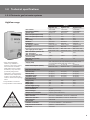
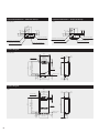
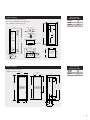
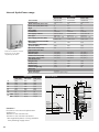
Quick Reference Guide J^mnkg Zgd @h 1.1 Bosch Gas Hot Water Systems Fh Fh Fh Fh NZeo^ EiZ @hm8Gnm @hm8J^mnkg 9 NZeo^ 9 EiZ NZeo^ D¥fb 9 9 9 9 9 9 NZeo^ D¥fbg NZeo^ D¥fbg NZeo^ D¥fbg NZeo^ D¥fbg NZeo^ D¥fbg NZe D¥ Bosch has been delivering hot water to Australian and New Zealand households for over 50 years. Manufacturing continuous flow water heaters since the 1930’s, Bosch has secured a name synonymous with quality and innovation that continues to drive the company today. The Bosch mission is to deliver the most reliable and efficient hot water appliances to fit the lifestyles of today’s modern households. As a result, Bosch now offers the largest range of continuous flow gas hot water systems on the market. This quick reference guide has been designed for specifiers, tradespersons, architects and retail staff involved in the selection, sizing and installation of Bosch gas hot water systems. 2 Contents 1 Bosch continuous flow gas hot water systems p4 1.1 Range overview p4 1.2 Technical specifications p5 1.2.1 Electronic gas hot water systems p5 1.2.2 HydroPower gas hot water systems p 11 1.2.3 Pilot gas hot water systems p 13 2 Commercial gas hot water systems p 14 2.1 32 Series – commercial applications p 14 2.2 Professional Packs p 15 2.3 Manifolding options p 16 2.4 Commercial flueing accessories p 17 3 Sizing guide p 17 4 Quick installation tips p 18 5 Installation regulations p 19 5.1 Minimum clearance of flue terminals p 19 5.2Installation locations for internal continuous flow gas hot water systems p 20 6 Temperature controllers for Highflow and 32 Series p 21 6.1 Highflow temperature controllers p 21 6.2 32 Series controllers 7 Frequently asked questions (FAQs) p 21 p 22 8 Contact p 23 8.1 Bosch Thermotechnology Australia p 23 8.2 Bosch Thermotechnology New Zealand p 23 8.3 For you own records p 23 3 1 Bosch continuous flow gas hot water systems 1.1 Range overview All Bosch hot water systems are continuous flow gas hot water systems, which means they only heat the required water on demand. They are wallhung, easy to install and much smaller than conventional storage systems. Highflow External HydroPower u 17, 21 and 26 litres per minute u 1 0, 13 and 16 litres per minute u External installation only u E xternal installation only u Antifrost as standard u E xclusive to Bosch – lighting a u 5 0°C limited models available in flame with water! Australia (standard model: 55°C) u F orget about installing a power u U p to 4 optional controllers can be point, replacing batteries, or installed for precise temperature control, increased energy lighting a pilot light u E asy installation efficiency and water saving features u M inimum 5.5 star energy efficiency 32 Series Internal HydroPower u 3 2 litres per minute u 1 0, 13 and 16 litres per minute u E xternal or internal* installation u I nternal* installation only u S uitable for large homes and u I deal for frost prone areas commercial applications u U p to 3 optional controllers can be installed for precise temperature u N o batteries, matches or power supply needed for ignition u E asy installation control (with KM3211WH models) u A dditionally, the 32Q model includes a built-in pump and a main controller, which allows for programmed water re-circulation into the hot water supply line u O utstanding energy efficiency and safety features Pilot Ignition** u 1 0, 13 and 16 litres per minute u E xternal installation only u S tanding pilot light u E asy installation *Internal installations require flueing as per AS 5601 or NZ 5621, respectively. Flue kits available from Bosch for 32 Series. For more information, please see page 17. **Pilot gas hot water systems not available in New Zealand. 4 1.2 Technical specifications 1.2.1 Electronic gas hot water systems Highflow range Models Part number 50°C limited (MP52)* Ignition type Flow rate L/min (25°C rise) Flow rate L/min (50°C rise) Mj/h Star rating Antifrost Installation Air supply / exhaust Gas type Gas supply pressure (kPa) Min. inlet water pressure for max. flow (kPa) Max. allowable inlet water pressure (kPa) Min flow rate (L/min) Electricity *50°C limited Highflow models only available in Australia. These units comply with Australian Standards 3489-2003 (licence number IPC20002). They have been specifically designed for applications, which require a maximum water temperature of 50°C. This eliminates the need for mechanical tempering valves. **Only available in Australia. ***Only available in New Zealand. 50°c This appliance delivers water NOT EXCEEDING 50°C in accordance with AS3498. Refer to AS/NZ3500, local requirements and installation instructions to determine if additional delivery temperature control is required. Highflow 17e YS1770RA YS1770RA5* Electronic 17 8.5 135 5.66 Standard External Power Flued NG/LPG NG: 1.13 – 3.0 LPG: 2.75 – 3.0 Highflow 21e YS2170RA YS2170RA5* Electronic 21 10.5 170 5.56 Standard External Power Flued NG/LPG NG: 1.13 – 3.0 LPG: 2.75 – 3.0 Highflow 26e YS2670RA YS2670RA5* Electronic 26 13 200 5.53 Standard External Power Flued NG/LPG NG: 1.13 – 3.0 LPG: 2.75 – 3.0 100 130 230 1,000 1,000 1,000 2.5 2.5 2.5 Supply (VAC) 230 - 240, 50 Hz (10 amp weatherproof power point recommended within 500 mm of the unit) Power Consumption (watts) In use: 40 Antifrost: 129 In use: 45 Antifrost: 129 In use: 51 Antifrost: 129 20 20 20 20 20 20 20 20 20 20 20 20 Pipe Connection Sizes Gas NG (mm) Gas LP (mm) Cold Water (mm) Hot Water (mm) Unit Dimensions Height (mm) Width (mm) Depth (mm) Carton weight (in kg) Domestic Warranty Parts and labour Heat exchanger Temperature controllers Optional Temperature Controllers Main controller Bathroom controller Sub-controller Accessories Lockable recess box Fully enclosed recess box Pipe cover (3/4”) (3/4”) (3/4”) (3/4”) 520 350 170 18 (3/4”) (3/4”) (3/4”) (3/4”) 520 350 170 19 (3/4”) (3/4”) (3/4”) (3/4”) 600 350 170 22 3 years 10 years (part only) 3 years (parts and labour) Standard: YPRM66XB**; Premium: YPRM67XB Standard: YPRS66XB**; Premium: YPRS67XB YPRP62XB 17 and 21e: RBHF50L**, 26e: RBHF26L** FERB70**, RBHF304WDA*** YPHC304 5 Connection dimensions – View from the top Connection dimensions – View from the top 17e & 21e 26e ?Zl8\hgg^\mbhg8J¥ ?Zl8\hgg^\mbhg8J¥ Gnme^m¦pZm^k8\hgg^\mbhg8J¥ Gnme^m¦pZm^k8\hgg^\mbhg8J¥ Hhp^k8\Z[e^8bgmZdbg`8ahe^ Age^m¦pZm^k8\hgg^\mbhg8J¥ Hhp^k8\Z[e^8bgmZdbg`8ahe^ Age^m¦pZm^k8\hgg^\mbhg8J¥ Product diagram 17e & 21e ª ^«8 ª^« 9bk¦bge^m :hmmhf8h_8\Zl^ ∼ :hmmhf8h_8\Zl^ ªHK8_eZf^8bglmZeeZmbhg8ib\a« ∼ >en^8m^kfbgZe Product diagram 26e 9bk¦bge^m :hmmhf8h_8\Zl^ ∼ :hmmhf8h_8\Zl^ 6 ªHK8_eZf^8bglmZeeZmbhg8ib\a« ∼ >en^8m^kfbgZe Product diagram Brick opening dimensions (mm)* Recess boxes for Highflow series 17e & 21e – RBHF50L (Australia only) Kb]^ ob^p Height 930 Width 345 Depth 145 *Minimum dimensions ff 26e – RBHF26L (Australia only) >khgm ob^p Dh\dbg`8[kZ\d^m8k^fhoZ[e^ Lhi ff ;ehl^]8ob^p Ehngmbg`8[kZ\d^m lihm8p^e]^] :Z\d8h_8k^\^ll8[hq Kihm8p^e]^] ff hnmlb]^ ff bglb]^ Ehngmbg` [kZ\d^m ff bglb]^ ff hnmlb]^ Gi^g ob^p Ehngmbg` [kZ\d^m ®= = Lhi8ob^p ff lehm _hk8mhi8[kZ\d^m ff ff hnmlb]^ ff ff bglb]^ ®= J^\^ll8[hq8[hmmhf \ho^k8ieZm^ ff ff :hmmhf = 8ff :hmmhf8ob^p ff Product diagram Brick opening dimensions (mm)* Fully enclosed recess box Height 930 Width 365 Depth 175 *Minimum dimensions FERB70 (Australia only) <hhk8]bf^glbhgl ff Kb]^ ob^p ff Lhi >khgm ob^p ff hnmlb]^ ff bglb]^ ff ff ff hnmlb]^ \Zm\a ff ff ff 7 Product diagram Brick opening dimensions (mm)* Fully enclosed recess box >khgm8ob^p Kb]^8ob^p RBHF304WDA (New Zealand only) Height Width 980 405 Depth 205 (if fully recessed) *Minimum dimensions ff ff ff The all new Highflow range represents the technological pinnacle of water heating. The new electronic series lets you enjoy uncompromised quality, higher capacities and even more temperature controllers. 8 32 Series (for large homes and commercial applications) Models Part number Ignition type Flow rate L/min (25°C rise) Flow rate L/min (50°C rise) Gas input - low (Mj/h) Gas input - high (Mj/h) Star rating Antifrost Installation Air supply / exhaust Gas type Gas supply pressure (kPa) *Internal installations require flueing as per AS 5601 / NZ 5621. Flue size: 100 mm. Flue kits available for 32 Series. For more information, please see page 17. Min. inlet water pressure for max. flow (kPa) Max allowable inlet water pressure (kPa) Min. flow rate (L/min) Electricity Bosch 32 KM3211WH Electronic 32 16 25 250 4.8 Standard Internal* or External Power Flued NG / LP NG: 1.13 – 3.0 LPG: 2.75 – 3.0 Bosch 32Q KM3211WHQ Electronic 32 16 25 250 4.8 Standard Internal* or External Power Flued NG / LP NG: 1.13 – 3.0 LPG: 2.75 – 3.0 200 200 900 900 3.5 3.5 Supply (VAC) 230 - 240, 50 Hz (10 amp weatherproof power point recommended within 500 mm of the unit) Power consumption (watts) In use (NG): 100 In use (LPG): 115 Antifrost: 115 In use (NG): 135 In use (LPG): 150 Antifrost: 140 20 (3/4”) 20 (3/4”) 20 (3/4”) 20 20 15 20 615 464 240 29 615 464 240 32 3 years parts and labour 3 years parts and labour 10 years heat exchanger (part only) 10 years heat exchanger (part only) 2 years parts and labour 2 years parts and labour 5 years heat exchanger (part only) 5 years heat exchanger (part only) Pipe Connection Sizes Cold water inlet (mm) Hot water outlet (mm) Hot water return (mm) Gas inlet (mm) Unit Dimensions Height (mm) Width (mm) Depth (mm) Weight (kg) Warranty Domestic Commercial Optional Temperature Controllers Main controller Sub-controller Flueing Vent cap Vertical flue kit Horizontal flue kit Accessories Quick connection cable System controller 3m cable for system controller 5m cable for system controller (3/4”) (3/4”) (1/2”) (3/4”) RCM3211 (included with 32Q) RCS3211 KMVC100 FKV32LTR FKH32LTR (requires vent cap KMVC100) KMQC0703339 (for 2 units in manifold) KMSC201 (for 3-6 units in manifold) 0700073 0700074 9 Connection dimensions – View from the top KM3211WH KM3211WHQ (Bosch 32) Connection dimensions – View from the top ?9K8AFD=L88J¥ (Bosch 32Q) ?9K8AFD=L8J¥ @GL8O9L=J8GMLD=L8 @GL8O9L=J8J=LMJF J¥ @GL8O9L=J8GMLD=L8J¥ 8J¥ ;GD<8O9L=J8AFD=L8J¥ ;GD<8O9L=J8AFD=L =D=;LJA;8OAJ=8AFD=L 8J¥ =D=;LJA;8OAJ=8AFD=L Product diagram* KM3211WH & KM3211WHQ =P@9MKL8HAH=8;GFF=;LAGF GH=J9LAGF8D9EH 9AJ8AFD=L :GLLGE8 G>8;9K= HGO=J8;GJ< 10 *All dimensions are in mm. Dimensions are identical for KM3211WH and KM3211WHQ; KM3211WHQ shown. 1.2.2 HydroPower gas hot water systems 1.1 External HydroPower range Models Part number Ignition type Flow rate L/min (25°C rise) Flow rate L/min (50°C rise) Mj/h Star rating Installation Air supply/ exhaust Gas type Gas supply pressure (kPa) *An exogel valve is recommended for areas that drop to 0°C for short periods. In areas prone to extended periods of frost and sub-zero temperatures, only Internal HydroPower models, external Highflow models and 32 Series models are suitable. Min. inlet water pressure for max. flow (kPa) Max. allowable inlet water pressure (kPa) Min. flow rate (L/min) Pipe Connection Sizes Gas NG (mm) Gas LP (mm) Cold water inlet (mm) Hot water outlet (mm) Unit Dimensions Height (mm) Width (mm) Depth (mm) Carton weight (kg) Warranty Parts and labour Heat exchanger Accessories Heat shield Exogel valve (Antifrost)* A B C D E 13H (mm) 405 845 533 240 68 Bosch 13H TF325-8G HydroPower 13 6.5 104 4.6 External Natural draft NG/LPG NG: 1.13 – 3.0 LPG: 2.75 Bosch 16H TF400-8G HydroPower 16 8 130 5.0 External Natural draft NG/LPG NG: 1.13 – 3.0 LPG: 2.75 60 100 130 800 800 800 3.5 3.5 3.5 20 15 15 15 20 15 15 15 20 15 15 15 (3/4”) (1/2”) (1/2”) (1/2”) 845 405 265 21 (3/4”) (1/2”) (1/2”) (1/2”) 845 405 265 22 (3/4”) (1/2”) (1/2”) (1/2”) 936 460 265 25 2 years 10 years (part only) 9 708 061 400.ZG1 H707 060 151* Product diagram Dimensions 10H (mm) 405 845 533 240 68 Bosch 10H TF250-8G HydroPower 10 5 79 5.1 External Natural draft NG/LPG NG: 1.13 – 3.0 LPG: 2.75 16H (mm) 460 936 533 240 82 @hkbshgmZe8 >en^ EZbg8 ;ho^k Ehngmbg`8 Hhbgm Agli^\mbhg8 Obg]hp ;he]8OZm^k8 Age^m ?Zl8Age^m @hm8OZm^k8 Gnme^m 11 Internal HydroPower range Models Part number Ignition type Flow rate L/min (25°C rise) Flow rate L/min (50°C rise) Mj/h Star rating Installation Air supply/ exhaust Gas Type Gas supply pressure (kPa) *Internal installations require flueing as per AS 5601 respectively NZ 5621. Min. water pressure for Max. flow (kPa) Max. allowable inlet water pressure (kPa) Min. flow rate (L/min) Pipe Connection Size Gas NG (mm) Gas LP (mm) Cold water inlet (mm) Hot water outlet (mm) Unit Dimensions Height (mm) Width (mm) Depth (mm) Carton weight (kg) Warranty Parts and labour Heat exchanger A B C D E F G H LPG NG 13H (mm) 400 755 228 140 500 196 30 R1/2” R3/4” 16H (mm) 460 755 334 140 530 166 30 R1/2” R3/4” Bosch 16H WR400-8G HydroPower 16 8 127 4.6 Internal* Natural draft NG/LPG NG: 1.13 – 3.0 LPG: 2.75 60 100 130 800 800 800 3.5 3.5 3.5 20 15 15 15 20 15 15 15 20 15 15 15 (3/4”) (1/2”) (1/2”) (1/2”) 680 360 220 12.5 (3/4”) (1/2”) (1/2”) (1/2”) 755 400 220 16 (3/4”) (1/2”) (1/2”) (1/2”) 755 460 220 20 2 years 10 years (part only) <kZn`am8 <bo^km^k >khgm8;ho^k D=<8bg]b\Zmhk8 fZbg8[nkg^k8 \hg]bmbhg ?Zl8;hgmkhe8 Keb]^ Flue Kits** Flue kits to suit Internal HydroPower appliances: 100mm to suit internal 10H 125mm to suit internal 13H & 16H **Not supplied by Bosch. Flueing available from plumbing supply stores ;abfg^r8 pbma8]kZn`am8 ]bo^km^k @^Zm8 ^q\aZg`^k D=<8_Zbenk^8 bg]b\Zmhk 12 Bosch 13H WR325-8G HydroPower 13 6.5 104 4.8 Internal* Natural draft NG/LPG NG: 1.13 – 3.0 LPG: 2.75 Product diagram Dimensions 10H (mm) 360 680 228 115 462 162 25 R1/2” R3/4” Bosch 10H WR250-8G HydroPower 10 5 79 4.5 Internal* Natural draft NG/LPG NG: 1.13 – 3.0 LPG: 2.75 OZm^k8>ehp8 K^e^\mhk ?Zl8 ;hgg^\mbhg ?Zl8oZeo^8 Zll^f[er A`gbmbhg8 ngbm OZm^k8oZeo^8 Zll^f[er 1.2.3 Pilot gas hot water systems* Models Part number Ignition type Flow rate L/min (25°C rise) Flow rate L/min (50°C rise) Mj/h Star rating Installation Air supply/ exhaust Gas type Gas supply pressure (kPa) Min. water pressure for max. flow (kPa) *Pilot range is not available in New Zealand. **An exogel valve is recommended for areas that drop to 0°C for short periods. In areas prone to extended periods of frost and sub-zero temperatures, only Internal HydroPower models, external Highflow models and 32 Series models are suitable. Max. allowable inlet water pressure (kPa) Min. flow rate (L/min) Pipe Connection Size Gas NG (mm) Gas LP (mm) Cold Water (mm) Hot Water (mm) Unit Dimensions Height (mm) Width (mm) Depth (mm) Carton weight (kg) Warranty Parts and labour Heat exchanger Accessories Heat shield Exogel valve (Antifrost)** A B C D 13P (mm) 405 845 533 240 Bosch 13P TF325 Standing pilot 13 6.5 100 3.9 External Natural draft NG NG: 1.13 – 3.0 Bosch 16P TF400 Standing pilot 16 8 130 4.3 External Natural draft NG NG: 1.13 – 3.0 NG: 100 NG: 150 1200 1200 1200 5.0 2.0 2.0 20 15 15 15 20 (3/4”) n/a 15 (1/2”) 15 (1/2”) 20 (3/4”) n/a 15 (1/2”) 15 (1/2”) 845 405 265 22 936 460 265 24 (3/4”) (1/2”) (1/2”) (1/2”) 845 405 265 21 2 years 10 years (part only) 9 708 061 400.ZG1 H707 060 151** Product diagram Dimensions 10P (mm) 405 845 533 240 Bosch 10P TF250 Standing pilot 10 5 82 4.6 External Natural draft NG/LPG NG: 1.13 – 3.0 LPG: 2.75 NG: 90 LPG: 55 16P (mm) 460 936 550 240 @hkbshgmZe8 >en^ EZbg8 ;ho^k Ehngmbg`8 Hhbgm Agli^\mbhg8 Obg]hp 9\\^ll8 HZg^e ;he]8OZm^k8 Age^m ?Zl8Age^m @hm8OZm^k8 Gnme^m 13 2 Commercial gas hot water systems 2.1 32 Series – commercial applications Benefits of the 32 Series for commercial applications u T he 32 Series is designed specifically for commercial use. Product diagram A flow rate of 32 litres per minute at a 25°C temperature N^gm \Zi rise makes the 32 Series a true commercial hot water system. Agm^kgZe8infi u T he 32 Series has a coated copper heat exchanger to prevent corrosion and deterioration. The internal copper piping is 25% thicker than standard domestic models for extra durability. J^fhm^ ;hgmkhee^k u D epending on the water volume required, the Bosch 32 ?Zl8Age^m ;he]8pZm^k8bge^m L^fi^kbg` NZeo^ models (KM3211WHNG/LP) can be installed as a single unit, manifold (see chapter 2.3) or are delivered as part of a Bosch Professional Pack, a pre-assembled system ahm8pZm^k8lniier including a 315 litre stainless steel storage tank (see chapter 2.2). u E xternal or internal* installation options make the 32 Series conveniently versatile. u U p to 3 optional temperature controllers can be installed with a Bosch 32 model (KM3211WHNG/LP only): 1 main controller (RCM3211) and up to 2 sub-controllers (RCS3211). u A dditionally, the 32Q model (KM3211WHQNG/LP) includes a built-in pump and a main controller, which allows for programmed water re-circulation on a ring main e.g. for peak usage times. The delivery time of hot water is reduced as well as unnecessary water usage. *Internal installations require flueing as per AS 5601 / NZ 5621. Flue kits are available for 32 Series. For more information, please see page 17. 14 The 32Q model allows for programmed water re-circulation on a ring main. The maximum length of the re-circulation pipe is 60m. 2.2 Professional Packs Professional Packs are specifically designed for commercial use. They are suitable for applications that require a large volume of hot water for peak demand. All Bosch Professional Packs come with the following components – Bosch hot water system, Bosch-Everlast stainless steel storage tank, built-in thermostat, shroud, PTR valve and pump. They are pre-assembled, ready to be installed and will be shipped directly to site. This means an easy installation and low set-up costs. The 315 litre Bosch-Everlast stainless steel storage tank included in Bosch Professional Packs comes standard with 32mm ports. Bosch-Everlast stainless steel storage tanks can also be purchased separately. A 315 litre model with 32 mm ports (part number: 315C2) as well as a 315 litre model with 50mm ports (part number: 315C250) is available. The 315C250 storage tank is not available as part of a Bosch Professional Pack. Model C31532WHNG (with shroud) Bosch Professional Packs come in the following system-tank combinations: Model C31532WHNG (without shroud; vent cap KMVC100 as shown is a required accessory for external installations) Models C31526ELP C31526ENG C31532WHLP C31532WHNG Gas Type LP NG LP NG Tank Size (ltr) 315 315 315 315 System Size 26e 26e 32 32 Internal installation: C31532WHLP and C31532WHNG may be installed internally with appropriate flueing. Please consult AS 5601 or NZ 5621. 15 2.3 Manifolding options Manifold 2 to 6 units Bosch 32 models (KM3211WHNG/LP) have the ability to be Product diagram linked in series (manifolded). For 2 units, the quick connection cable (KMQC0703339) can be used to allow the N^gmbeZmbhg _en^ units to share the work load. 3 to 6 units can be used in Fh CEK; Fh Fh rotation with a fully electronic rotation manifold system controller (KMSC201). The system controller allows the work J^fhm^ ;hgmkhee^k load to be shared evenly between the manifolded units. 9 9 * Note: When manifolding 2 or more Bosch 32 models, you are required to install a main controller (RCM3211) for electronic staging. 9 ?Zl8Kniier89 OZm^k8Kniier 9 @hm8Gnm KmkZbg^k =qm^kgZe infi @hm8Gnme^ml 9 @hm8J^mnkg 9 9 Manifolds can also be combined with Bosch-Everlast stainless steel tanks (315 ltr storage capacity). =qiZglbhg mZgd 9 NZeo^ EiZ 9 9 NZeo^ D¥fbg 9 Bosch Commercial combination sizing guide Bosch 32 Series manifolds can be combined with Bosch- The Bosch 26e Highflow, along with being the flagship of the Everlast stainless steel tanks (for tank part numbers see domestic range of water heaters, can also be used in page 14). The table below shows some of the possible commercial applications. One option is to hydraulically burner-tank combinations and the approximate capacities the manifold these units in conjunction with a Bosch-Everlast manifolds can deliver in the 1st and 2nd hour at a 50°C storage tank. temperature rise. System 26e 26e 26e 26e 26e 32 32 32 32 32 16 Tank size 315 315 315 315 315 315 315 315 315 315 ltr ltr ltr ltr ltr ltr ltr ltr ltr ltr Number of Bosch units 1st hour litres at a 50°C rise 2nd hour litres at a 50°C rise Gas usage (MJ/h) 1 2 3 4 5 1 2 3 4 5 1095 1875 2655 3435 4215 1275 2235 3195 4155 5115 780 1560 2340 3120 3900 960 1920 2880 3840 4800 200 400 600 800 1000 250 500 750 1000 1250 There are many more combinations than are listed. Please refer to the Bosch customer contact centre (Australia: 1300 30 70 37; New Zealand: 0800 54 33 52) or visit www. bosch.com.au to find your local Bosch agent. 2.4 Commercial flueing accessories All internal gas water heaters must be flued in Flueing Accessories accordance with AS 5601 or NZ 5621. For the Bosch 32 Series there is a horizontal or vertical flue kit available @hkbshgmZe8>en^8Cbm ª>C@DLJ«² for internal installations. N^kmb\Ze8>en^8Cbm ª>CNDLJ« The maximum flue length for a vertical flue with 1 elbow >e^qb[e^8>en^ >e^qb[e^8>en^ is 13m. FKH32LTR u 1 00mm gas cowl (requires vent cap u 1 .5m x 100mm diameter KMVC100) gas flex (three pieces) u 1 00mm diameter u F lue pipe adaptor (three flexible flue, 5 pieces) EZq8f Horizontal flue kit FKV32LTR EZq8f Vertical flue kit ;hg]^glZmbhg8 mkZi =qm^kgZe8o^gm8\Zi ªCEN;« meters long u S upport struts (two u f lue sleeve pieces) u a djustable wall u 6 mm x 3m condensation hose penetration sleeve (two pieces) *Vent cap KMVC100 required with horizontal flue kit FKH32LTR. u c lamp 3 Sizing guide Climate COLD <Zkpbg No. of bathrooms 1 :kbl[Zg^ H^kma 9]^eZb]^ Kr]g^r ;Zg[^kkZ E^e[hnkg^ 9n\deZg] @h[Zkm ;akblm\ank\a 2 2+ 3+ Product Name MODERATE TROPICAL Litres Litres Litres HydroPower Pilot Electronic Highflow HydroPower Pilot Electronic Highflow 16 16 17 – – 21 or 26 10 or 13 10 or 13 17 16 16 17 or 21 or 26 10 or 13 10 or 13 17 16 16 17 or 21 Electronic Highflow 26 26 26 Commercial Series 32 32 32 Guide only, circumstances may vary. Please consult your retailer for specialist advice in your area. Cooler climates For external HydroPower and Pilot range hot water systems model, an internal or external 32 Series model or an external the Exogel valve is recommended in areas that drop to 0°C Highflow model are suitable. The 32 Series and the Highflow for short periods. In areas prone to extended periods of frost range come standard with Antifrost protection. and sub-zero temperatures, only an internal HydroPower 17 4 Quick installation tips The installation tips provided in this quick refererence guide are a guide only. Please refer to the latest AS 5601 or NZ 5621 edition and local authority guidelines. Bosch gas hot water systems are to be installed by an authorised person only. u S elect the water heater that best suits the customer‘s needs. u C heck cold water pressures to ensure they are within the min/max range required. The installation of a pressure limiting valve may be required for pressures above 800kPa (refer to installation manuals). u C heck gas type required. u C heck maximum gas load of installation (if other appliances are or may be installed in the future). This will influence a number of factors such as: 1. P roperty gas service size, regulator and gas meter 2. N umber and size of cylinders, regulator capacity and size/capacity and house pipe sizing (natural gas); house pipe sizing (LPG). u P osition the water heater in compliance with AS 5601 / NZ 5621, manufacturers instructions and local authority guidelines. u K eep hot water piping to a minimum. Consult AS 3500 / NZ 3500 for pipe sizing. u M ount water heater on an external or internal wall, depending on the water heater model, using fixing capable u C onnection of the gas supply to the appliance must be via an approved isolation valve at the unit. u R efer to technical specifications for the correct gas connection size. u P urge and flush gas piping prior to connection to unit. u C onnection of cold water piping is via an approved isolation valve. u F lush cold water piping of debris prior to connection to the unit. u S ee technical specifications for cold and hot water connection sizes to the unit. u I nstall temperature control pads if desired (available for Highflow and 32 Series). DO NOT ATTACH THE TEMPERATURE CONTROLLER TO ELECTRONIC WATER HEATERS WHILST THE UNIT IS POWERED. u A fter completing the installation of the unit, remove the gas test point sealing screw, connect your manometer to the gas inlet test point, turn on the water, gas and (if applicable) power supplies to the unit. u O perate all other gas appliances with the water heater of supporting the unit weight (see technical operating at maximum water flow from the hot tap and specifications). confirm that the gas inlet pressure does not drop below u H ighflow range and 32 Series: Electricity supply (VAC): 230-240, 50Hz (10 amp weatherproof power point recommended within 500 mm of the unit). u C onsult AS 5601/NZ 5621 and determine the correct gas pipe sizing for the installation. (Do not forget to include the pressure range required (see technical specifications). Isolate gas supply and retighten test point. u P lease refer to installation manuals for full commissioning procedures. u C onfirm that the water heater delivers the temperature or make provision for existing or future gas loads such the consumer requires, explain the appliance operation as heating, cooking appliances, etc.) to the consumer and hand over the operation instructions. Please leave your contact details with the consumer. 18 5 Installation regulations 1.1 The installation regulations provided in this quick reference guide are a guide only. Please refer to the latest AS 5601/NZ 5621 edition and local authority guidelines. 5.1 Minimum clearance of flue terminals Natural draft Fan assisted Bosch hot water systems with natural draft flue terminals Hot water systems with fan assisted flue terminals in the are: External and Internal HydroPower ranges as well as the Bosch product range are: Highflow range and Bosch 32 Series. Pilot Ignition range. Installation diagram Z c O _ g c a ]hhk a a d ^ ^ 8 ] H ` ] L A \ \ L c E ` d [ L T = flue terminal P = Electricity meter or fuse box I = Mechanical air inlet W = Openable window M = Gas meter Shading indicates prohibited areas for flue terminals 19 Item a b c d e f g From any other flue terminal, cowl, or combustion air intake* j Horizontally from an opening window, door, non-mechanical air inlet. Or other opening into a building with the exception of sub floor ventilation Appliances up to 150 MJ/h Appliances over 150MJ/h input up to 200 MJ/h input Appliances over 200 MJ/h input up to 250 MJ/h input* Appliances over 250 MJ/h* All fan-assisted flue applications, in the direction of discharge From a mechanical air inlet, including spa blower Vertically below an openable window, non-mechanical air inlet, or any other opening into a building with the exception of sub-floor ventilation: Space heaters up to 50 MJ/h Other appliances up to 50 MJ/h Appliances over 50 MJ/h and up to 150 MJ/h input Appliances over 150 MJ/h input n Minimum Clearance (mm) Fan Assisted 300 500 300 500 1000 500 150 200 300 300 300 1000 500 75 500 500 500 300 500 1500 1500 1500 – 1500 300 300 500 1500 1500 1000 150 500 1000 1500 150 500 1000 1500 Below eaves, balconies and other projections Appliances up to 50 MJ/h input Appliances over 50 MJ/h input From the ground, above a balcony or other surface* From a return wall or external corner* From a gas meter (M) From an electricity meter or fuse box (P) From a drain pipe or soil pipe Horizontally from any building structure or obstruction facing a flue terminal h k Minimum Clearance (mm) Natural Draft *Unless appliance is certified for closer installation. 5.2 Installation locations for internal continuous flow gas hot water systems Installation diagram æ8\f \f æ8 Internal continuous flow gas hot water systems in the Bosch product range are: Internal HydroPower range, internal installations of the 32 Series (external installations also possible). Please note that appropriate flueing is required for internal installations. Prohibited internal installation locations for instantaneous water heaters are: æ8\f æ8\f æ8\f bedrooms, bathrooms, toilet rooms, or combined living/sleeping rooms. Please refer to AS 5601/NZ 5621, installation instructions, and local authority guidelines. This diagram of installation locations serves as a guide only. Please refer to AS 5601/NZ 5621 and local authority guidelines. 20 6 Temperature controllers for Highflow and 32 Series Bosch recommends the installation of temperature controllers with the Highflow range and the 32 Series. Fault codes displayed on the controller make fault diagnosis as easy as possible. They also allow temperature control accurate to the single degree. 6.1 Highflow temperature controllers Two different types of Highflow temperature controllers are If several controllers are used, Bosch recommends a parallel available: Standard* and Premium. There is a main and a installation; all single wires going back to the water heater. The bathroom controller of each type as well as a common maximum length of any cable should be 20m. For installation sub-controller, which can be used in conjunction with both and operation instructions, please refer to the installation and Standard and Premium controllers. operation manual. Only controllers of the same type can be used together; DO NOT ATTACH THE TEMPERATURE CONTROLLER TO THE It is not possible to mix Standard and Premium main and HIGHFLOW WATER HEATER WHILST THE UNIT IS POWERED. bathroom controllers. Part numbers A maximum of 4 controllers can be installed with the Highflow range – 1 main controller, 1 bathroom controller Controller name Part number and 2 sub-controllers. Standard main controller YPRM66XB* Standard bathroom controller YPRS66XB* Highflow temperature controllers also offer the Bosch Water Premium main controller YPRM67XB Saver function, which either stops the water flow Premium bathroom controller YPRS67XB automatically (Premium controllers) or sounds an audible Sub-controller YPRP62XB alarm (Standard controllers) once the pre-defined amount *Standard controllers available in Australia only. of water has been delivered. 6.2 32 Series controllers As with Highflow temperature controllers, 32 Series controllers For installation and operation instructions, please refer to offer temperature control accurate to the single degree. the installation and operation manual. DO NOT ATTACH THE TEMPERATURE CONTROLLER TO THE Coupled with the 32Q model (KM3211WHQNG/LP), the main HIGHFLOW WATER HEATER WHILST THE UNIT IS POWERED. controller offers a circulation mode, which includes the option to time the circulation of hot water to the water outlets, e.g. for peak usage times. The main controller (RCM3211) is included with the 32Q. A maximum of 3 controllers can be fitted with Bosch 32 models (KM3211WHNG/LP) – 1 main controller and 2 sub-controllers. Part numbers Controller name Part number Main controller RCM3211 Sub-controller RCS3211 21 7 Frequently asked questions (FAQs) uAre water flow restrictors compatible with Bosch hot 32 Series. However, maximum temperatures can be water systems? increased up to 75°C (Highflow range) and 83°C (32 Series), Yes, but they must allow a minimum flow rate of 9 litres if necessary. We recommend that the maximum temperature per minute. should only be adjusted by an authorised person. Please refer to the installation and operation manual. u A re Bosch hot water systems compatible with all taps and shower heads? u W hat is the maximum number of temperature controllers They are compatible with most taps but some flick mixer that can be used with a Highflow range installation? taps have a flow rate that is below the minimum required 4 temperature controllers – 1 main, 1 bathroom and 2 for operation. sub-controllers. Premium and Standard main and bathroom controllers cannot be mixed. u W hat size of LPG gas cylinder should be used with Bosch hot water systems? Bosch 32 models (KM3211WHNG/LP) can be used with up HydroPower and Pilot range models with a flow rate of 10 to 3 temperature controllers - 1 main controller and 2 and 13 litres should be connected to at least one 45kg sub-controllers. Bosch 32Q models (KM3211WHQNG/LP) LPG cylinder. HydroPower and Pilot range models with include 1 main controller as standard. a flow rate of 16 litres as well as Highflow and 32 Series hot water systems should be connected with two 45kg cylinders with an auto changeover regulator. u I s the setting of gas pressures done by the manufacturer? No. Even though all Bosch units are tested in the factory; u H ow often should the gas appliance be serviced? Gas inlet pressures and burner pressures (for the All domestic gas appliances should be serviced at intervals mechanical units) need to be set and checked at every not exceeding 2 years. service to ensure correct operation. Commercial gas hot water applications should be serviced at intervals never exceeding 1 year. u W hat does the Bosch warranty cover? The Bosch warranty covers manufacturing defects only. If the problem has been caused by poor installation or u W hich tempering valve is compatible with which Bosch hot water system? other factors, depending on the case, the consumer or installer is then responsible for the costs. All continuous flow units must be connected with a high performance tempering valve (green cap). u W hy is the installation position so important? The positioning of the water heater is very important as it u C an the factory-set maximum temperature of Highflow another aspect that has to be taken into consideration For safety reasons, the maximum temperature is factory- when installing the appliance. set at 55°C with the Highflow range and at 60°C with the 22 may affect water flow and lag times. Safety regulations are (55°C) and 32 Series models (60°C) be changed? 8 Contact 1.1 Our hot water systems are designed for long life and high performance. However, if a problem does arise, our expert customer service team and network of authorised service agents in Australia and New Zealand will be ready to assist you. 8.1 Bosch Thermotechnology Australia Customer Contact Centre: Mailing address: Internet: Hotline: 1300 30 70 37 Robert Bosch (Australia) Pty. Ltd. www.bosch.com.au Fax: 1300 30 70 38 Thermotechnology, Technical Department [email protected] Locked Bag 66 Clayton South VIC 3169 8.2 Bosch Thermotechnology New Zealand Customer Contact Centre: Mailing address: Internet: Hotline: 0800 54 33 52 Robert Bosch Thermotechnology www.bosch.co.nz Fax: 0800 54 33 55 P.O. Box 19026 [email protected] Avondale Auckland 1746 8.3 For your own records Your Bosch Sales Representative Other Bosch Contacts: Name: Name: Phone: Phone: Mobile: Mobile: Fax: Fax: Mailing Address: Mailing Address: 23 Fh Fh Fh Fh @h 9 9 =qm^kgZe infi NZeo^ EiZ Robert Bosch (Australia) Pty. Ltd. 1555 Centre Road @hm8Gnm @hm8J^mnkg 9 NZeo^ 9 EiZ 9 9 9 NZeo^ D¥fbg NZeo^ D¥fbg NZeo^ D¥fbg Clayton Victoria 3168 Phone: (03) 9541 5555 Fax: (03) 9541 5595 Sales Hotline: 1300 30 70 37 Sales Fax: 1300 30 70 38 www.bosch.com.au www.bosch.co.nz New Zealand Sales Hotline: 0800 54 33 52 Sales Fax: 0800 54 33 55 Printed in Australia Whilst every care has been taken in the preparation of this publication, Bosch does not warrant the accuracy or completeness of the information in this publication and Bosch reserves the right to alter specifications without notice. To the extent permitted by law, Bosch excludes all liability, including negligence, for any loss incurred in reliance on the contents of this publication. Printed May 2008. U-bahn design. 9 9 9 9