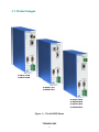
1
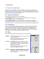
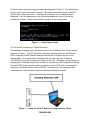
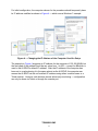
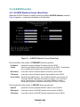
AI-SRVR ARCNET Server to Ethernet Client Software Manual # TD000200-0MC Trademarks BASautomation, Contemporary Controls and CTRLink are registered trademarks of Contemporary Control Systems, Inc. BACnet is a registered trademark of the American Society of Heating, Refrigerating and Air-Conditioning Engineers, Inc. Powered by Sedona Framework is a trademark of Tridium, Inc. Other product names may be trademarks or registered trademarks of their respective companies. Copyright © Copyright 2014, by Contemporary Control Systems, Inc. All rights reserved. No part of this publication may be reproduced, transmitted, transcribed, stored in a retrieval system, or translated into any language or computer language, in any form or by any means, electronic, mechanical, magnetic, optical, chemical, manual, or otherwise, without the prior written permission of: Contemporary Control Systems, Inc. 2431 Curtiss Street Downers Grove, Illinois 60515 USA Tel: Fax: E-mail: Web: +1-630-963-7070 +1-630-963-0109 [email protected] http://www.ccontrols.com Contemporary Controls Ltd 14 Bow Court Fletchworth Gate Coventry CV5 6SP UK Tel: Fax: E-mail: Web: +44 (0)24 7641 3786 +44 (0)24 7641 3923 [email protected] http://www.ccontrols.co.uk Contemporary Controls (Suzhou) Co. Ltd 11 Huoju Road Industrial Park — Science & Technology New District, Suzhou PR China 215009 Tel: Fax: E-mail: Web: +44 (0)24 7641 3786 +44 (0)24 7641 3923 [email protected] http://www.ccontrols.eu Contemporary Controls GmbH Fuggerstraße 1 B D-04158 Leipzig Deutschland Tel: Fax: E-mail: Web: +49 (0)341 520359 0 +49 (0)341 520359 16 [email protected] http://www.ccontrols.eu Disclaimer Contemporary Control Systems, Inc. reserves the right to make changes in the specifications of the product described within this manual at any time without notice and without obligation of Contemporary Control Systems, Inc. to notify any person of such revision or change. WARNING — This is a Class A product as defined in EN55022. In a domestic environment this product may cause radio interference in which case the user may be required to take adequate measures. TD000200-0MC 2 1 Table of Contents 1 TABLE OF CONTENTS........................................................................................... 3 2 HISTORY ................................................................................................................. 4 3 INTRODUCTION ...................................................................................................... 4 3.1 4 Product Images ................................................................................................. 5 OPERATION ............................................................................................................ 6 4.1 General Considerations .................................................................................... 6 4.1.1 Functions of Operation .................................................................................. 6 4.1.2 Configuration ................................................................................................. 6 4.1.3 LEDs.............................................................................................................. 6 4.1.4 Access Options ............................................................................................. 7 4.1.4.1 Terminal Emulators — Hercules, HyperTerminal © and PuTTY ............. 7 4.1.4.2 Console Port Access .............................................................................. 7 4.1.4.3 Telnet Access ......................................................................................... 7 4.1.4.4 Initial Access by a Telnet Session .......................................................... 8 4.1.4.5 Web Browser Access (Read Only) ....................................................... 10 4.2 AI-SRVR Function ........................................................................................... 11 4.2.1 AI-SRVR Statistics Screen (Read Only) ...................................................... 11 4.2.2 AI-SRVR Configuration................................................................................ 12 4.3 AI-PROXY Function ........................................................................................ 16 4.3.1 AI-PROXY Statistics Screen (Read Only) ................................................... 18 4.3.2 AI-PROXY Configuration ............................................................................. 19 TD000200-0MC 3 2 History 2/1/2005 Initial Release 7/1/2006 Expanded LED and Proxy functionality 7/1/2014 Added TCP timeouts, Hostname and expanded Server functionality 3 Introduction The AI-SRVR employs a CPU (running the Linux operating system) to perform as an ARCNET Server to an Ethernet Client. There are several models which offer different transceiver options. The AI-SRVR-1/CXB accommodates coaxial cabling at a data rate of 2.5 Mbps. The AI-SRVR-1/TB5 has an RJ-45 port for dipulse signals at a rate of 2.5 Mbps. Two other models are designed for EIA-485 signalling — the AI-SRVR-1/485D accepts DC-coupled signals at all of the common data rates while the AI-SRVR-1/485X passes AC-coupled signals at three popular data rates. On the ARCNET side, the unit operates transparently. No changes or protocol overhead are needed. The unit will appear as just another node within an ARCNET network. The Ethernet port accepts 10BASE-T or 100BASE-TX signals, continuously monitors connectivity and supports TCP/IP and UDP protocols. This port supports the PAUSE function for full-duplex operation and the backpressure scheme for half-duplex data. It auto-negotiates the port parameters of data rate, duplex mode and flow control. With the help of incoming packet buffering, multiple Ethernet users can send messages to any ARCNET node. Complete ARCNET frames are encapsulated. When communicating from ARCNET to Ethernet, frames are sorted by Source ID and buffered in 255 FIFO mailboxes. Mailbox “0” is used for broadcast messages. Ethernet users can receive packets from specific nodes or poll mailbox buffers of specific nodes. An included function called AI-PROXY allows one ARCNET node to communicate via an Ethernet backbone link (either wired or wireless) to another ARCNET node in a completely different LAN. This arrangement requires two units — one in each LAN. Each unit acts as a local proxy for the represented node situated in the remote LAN. When using the AI-SRVR function, the unit can be set to accept only messages addressed to it or all messages from any ARCNET node, regardless of the intended destination. Configuration can be accomplished in two ways — through an EIA-232 console port (COM2) connected to a Windows®-based terminal emulation application such as HyperTerminal® — or through a Telnet session where simple password protection is provided. A second serial port (COM1) is for factory service only. The unit is powered from a wide-range, low-voltage AC or DC source — and redundant power connections are present for backup considerations. It comes with all that is needed for either DIN-rail or panel mounting. The switch front panel features a general status LED and there are LEDs for link status, activity, and data rate of each port. Additional helpful technical information can be found at: www.ccontrols.com/support/aisrvr.htm TD000200-0MC 4 3.1 Product Images AI-SRVR-1/CXB AI-SRVR-8/CXB AI-SRVR-1/TB5 AI-SRVR-8/TB5 AI-SRVR-1/485D AI-SRVR-8/485D AI-SRVR-1/485X AI-SRVR-8/485X Figure 1 — The AI-SRVR Series TD000200-0MC 5 4 Operation 4.1 General Considerations Configuration is accomplished while the AI-SRVR is connected to a suitable device, either a computer terminal or a computer running a terminal emulation program such as HyperTerminal or PuTTy. The connection is made via the AI-SRVR serial port (console port) which uses standard EIA-232 protocol. 4.1.1 Functions of Operation The unit has the following two ways of functioning: In the AI-SRVR Function, the unit performs as an ARCNET server for delivering ARCNET packets to one or more Ethernet clients. In the AI-PROXY Function, an ARCNET node can communicate via an Ethernet backbone to an ARCNET node in a different LAN. This requires two AI-SRVRs — one in each ARCNET LAN — each acting as a proxy for the remote node being represented. 4.1.2 Configuration To avoid communication difficulties, configuration should be accomplished before the unit is connected to either the ARCNET or Ethernet network. Whether the unit is configured by a Telnet session or through its console port, the procedure and the display screens are the same. However, the screens used for the AI-SRVR Function differ slightly from those displayed for the AI-PROXY Function. 4.1.3 LEDs Several LEDs aid in monitoring performance and in troubleshooting: ARCNET: The RX LED glows green when the unit receives data from the ARCNET LAN. The ACT LED flashes yellow whenever the unit’s CPU and ARCNET chip communicate. Ethernet: The LINK/ACT LED glows if a valid link exists to an operating Ethernet device and indicates speed by colour: green for 100 Mbps and yellow for 10 Mbps. It flashes to indicate activity. The DUP LED glows green to indicate full-duplex operation and yellow for half-duplex. STATUS: During boot-up, this green LED flashes. Once all files have loaded — about 15 seconds on newer units, 50 seconds for older units) — it glows solid to indicate the unit is operational. TD000200-0MC 6 4.1.4 Access Options The AI-SRVR can be accessed through its Ethernet port or its console (serial) port. Initially, the unit must be configured so that its IP address is set to a value placing it on the same subnet as that in which it is being installed. The simplest way to do this is via the console port. If a null-modem cable is not available, the unit can also be configured via its Ethernet port and a Telnet session as described in Section 4.1.4.4. 4.1.4.1 Terminal Emulators — Hercules, HyperTerminal © and PuTTY These terminal emulators can connect to the AI-SRVR in either of two ways: by Telnet or the unit’s console port using a null-modem cable (not provided). Earlier versions of HyperTerminal lacked Telnet capability. Once a connection is made, either method of access involves the same procedure and displays the same screens. 4.1.4.2 Console Port Access With a serial null-modem cable connected between the unit’s COM2 (DE-9) port and a computer terminal (or a computer performing terminal emulation), the unit can be monitored and configured. For proper EIA-232 communication: Set the Baud rate to 57600. Set the Data bits to 8. Set the Parity to None. Set the Stop bits to 1. Set the Flow control (handshaking) to None. Set Emulation to ANSI. With console port access, no login is required. As soon as the unit boot-up process is completed and the serial cable is connected, the screen will display the statistics screen for the most recently used function — AI-SRVR or AI-PROXY. 4.1.4.3 Telnet Access The AI-SRVR includes a Telnet server. It is factory-programmed with a default IP address of 192.168.92.68 and a Class C subnet mask of 255.255.255.0. Changing the IP address is strongly encouraged. Once the AI-SRVR has finished booting and its Ethernet port has been connected to the Ethernet network, Telnet communications are possible. However, the AI-SRVR and any computer communicating with it must share the same subnet. If they are not on the same subnet, they cannot communicate. TD000200-0MC 7 A Telnet session requires a login procedure as displayed in Figure 2. The default login string is “root” and it is echoed on screen. The default Password string is “ccsi2431”, but it is NOT echoed on screen. If the login is successful, a Linux bash prompt is displayed. From the bash prompt, two commands enable the user to choose the operational function. These commands are config-srvr and config-proxy. Figure 2 — Telnet Login Screen 4.1.4.4 Initial Access by a Telnet Session The hardware arrangement for the initial setting of the IP address via a Telnet session appears in Figure 3. The PC should be temporarily disconnected from the Ethernet LAN in case the AI-SRVR default address matches that of another device on the existing LAN. If it is certain that no existing device on the LAN uses IP address 192.168.92.68, then the computer can remain in the LAN. Otherwise, the procedure for changing the IP address employs the creation of a temporary LAN composed of nothing but the AI-SRVR, the computer used to configure it and a CAT5 cable connecting the computer to the Ethernet port of the AI-SRVR. Consequently, this computer will be unavailable for normal network functions until this procedure is finished. Figure 3 — Setup for Initial IP Address Configuration by Telnet TD000200-0MC 8 For initial configuration, the computer chosen for the procedure should temporarily have its IP address modified as shown in Figure 4 — which uses a Windows 7 example. Figure 4 — Changing the IP Address of the Computer Used for Setup The example in Figure 4 suggests an IP address for the computer of 192.168.92.69, but the final quad of the address could be any value from 1 to 255 — except for 68 which is used in the AI-SRVR’s default IP address. After the IP address of the computer has been set to a value placing it in the same subnet as the AI-SRVR, the computer can access the AI-SRVR via the unit’s default IP address using either a web browser or a Telnet session. However, web browser access allows only monitoring — configuration can only be done via Telnet or through the console port. TD000200-0MC 9 4.1.4.5 Web Browser Access (Read Only) Although the AI-SRVR must be configured via either its console port (Section 4.1.4.2) or via a Telnet session (Section 4.1.4.3), statistics can be monitored by a web browser run from any Internet-capable computer. The AI-SRVR is factory-programmed with a default IP address of 192.168.92.68 and a Class C subnet mask of 255.255.255.0. Changing the IP address is strongly encouraged. A sample statistics page appears in Figure 5. Figure 5 — The AI-SRVR Statistics Web Page TD000200-0MC 10 4.2 AI-SRVR Function 4.2.1 AI-SRVR Statistics Screen (Read Only) When the AI-SRVR Function is initially invoked, the default AI-SRVR Statistics screen of Figure 6 appears — presenting information in 8 data fields. Figure 6 — AI-SRVR Statistics Screen (Read Only) On the left side of the screen, 5 ETHERNET fields are reported: IP Address reports the currently assigned IP Address of the AI-SRVR. Clients lists how many Ethernet clients are connected to the AI-SRVR. Accessing the unit by web browser temporarily increases this count by one. RX Packets counts the number of Ethernet packets received by the AI-SRVR. TX Packets counts the number of Ethernet packets transmitted by the AI-SRVR. Server Status identifies the AI-SRVR status. If the AI-SRVR software is running the unit should be ONLINE, otherwise the software is inactive. This could occur during Telnet access if config-srvr is run while AI-PROXY is active. Executing config-proxy would then confirm that AI-PROXY is ONLINE. On the right side of the screen, 3 ARCNET values are reported: Node ID reports the currently assigned ARCNET node ID of the AI-SRVR. RX Packets counts the number of ARCNET packets received by the AI-SRVR. TX Packets counts the number of ARCNET packets transmitted by the AI-SRVR. TD000200-0MC 11 The screen of Figure 6 offers three case-insensitive options: R forces an immediate refresh of the screen. Otherwise, the screen refreshes itself automatically every 10 seconds. S opens the Setup Screen for configuration (Section 4.2.2). C resets all 4 packet counters. 4.2.2 AI-SRVR Configuration By pressing “S” from the AI-SRVR Statistics Screen, the default AI-SRVR Configuration Screen of Figure 7 appears to allow control of 16 parameters. All fields in the left column (except Node ID) are modified by pressing the space bar. These are: Function should be toggled to the desired mode: SERVER or PROXY. Boot Protocol is NONE by default, but can be toggled to DHCP. Hostname AI-SERVER by default, it can be 32 alpha-numeric or hyphen characters. Node ID is 1 by default, but a value from 1–255 can be entered. Speed is 2.5Mbs by default, but can be set from 156kbs to 10Mbs. The 7.5Mbs option is the undocumented "reserved" speed of the COM20022 — but it is not recommended for use. Ext Timeout is STD by default, but can be set to 16X, 8X or 4X. Recon Timeout is STD by default, but can be set to 64Nodes, 32Nodes or 16Nodes. Receive All (promiscuous mode) is ON by default, but can be toggled to OFF. Figure 7 — AI-SRVR Configuration Screen TD000200-0MC 12 All fields in the centre and right columns of Figure 7 require numerical values: IP Addr is 192.168.92.68 by default. Defining a new address before placing the unit into service is highly recommended. Netmask is the subnet mask — 255.255.255.0 by default. Gateway is 192.168.92.1 by default. If your Ethernet LAN does not have a gateway, set this value to 0.0.0.0. DNS #1 is the IP address of the chosen Domain Name Server (if one is desired at all). It is 0.0.0.0 by default. DNS #2 is 0.0.0.0 by default. Netmask is the subnet mask — 255.255.255.0 by default. Rx Broadcast is Enable by default, but can be toggled to Disable. Tx Enable is Enable by default, but can be toggled to Disable. FIFO Depth is 5 by default, but it can be set from 1 – 10. TCP Port is 5001 by default, but can be 1025 – 65535. UDP Port is 5001 by default, but can be 1025 – 65535. Keepalive Time is 30 seconds by default, but can be 1 – 65535. Keepalive Interval is 10 seconds by default, but can be 1 – 65535. Keepalive Probes is 3 by default, but can be 1 – 65535. TCP Retries is 5 by default, but can be 1 – 65535. TCP FIN Timeout is 30 seconds by default, but can be 1 – 65535. EDITING IN FIELDS REQUIRING ENTERED VALUES: The default cursor position is in the Function field. Use the Tab key to advance from field to field. Within each field, use the cursor arrow keys to position the cursor and the backspace key to erase characters to the left of the cursor. CTRL-V toggles the editing mode between the default OVERTYPE: OFF (characters are inserted as you type) and OVERTYPE: ON (characters are replaced as you type). EXPLANATION OF EACH FIELD For the NETWORK configuration at the top of the screen, first set the Function to either SERVER (if Ethernet clients are to access your ARCNET) or to PROXY (if you plan to set up an Ethernet backbone between nodes in separate ARCNET LANs). The Boot Protocol is the next item to be configured. If the IP address is to be set via Dynamic Host Configuration Protocol, the DHCP option should be selected. When DHCP is in effect, the following 5 fields are ignored: IP Addr, Netmask, Gateway*, DNS #1 and DNS #2. If a fixed IP address is to be used, then NONE should be selected and the five fields listed in the previous sentence should be changed to values that are appropriate for your Ethernet network. * NOTE: If AI-SRVR units connect to the network through routers, this is the address of the router through which access is gained to the rest of the network or to the Internet. TD000200-0MC 13 Then, the Hostname field should be modified if desired. Next, the BRIDGE fields should be configured. The Node ID can be any value from 1 through 255 so long as the designated value is unique within the ARCNET network to which it belongs. Speed can be set to 156kbs, 312kbs, 625kbs, 1.25Mbs, 2.5Mbs, 7.5Mbs or 10Mbs. The 7.5Mbs option is not recommended, but it is provided if a special need exists. * NOTE: The TB5 and CXB transceivers only support 2.5 Mbps. The 485X transceiver only supports 1.25 Mbps, 2.5 Mbps and 5 Mbps. By default, the Ext Timeout (extended timeout) value of the AI-SRVR is set to STD (no extended timeout). If the physical size of the network is so great that extended timeouts are required, then the Ext Timeout value can be increased to 16X, 8X or 4X. However, care must be exercised that all nodes within the ARCNET network are set to the same extended timeout value — or the network will suffer disruptions. The COM20022 ARCNET controller within the AI-SRVR is capable of programmable reconfiguration timeout values. The Recon Timeout setting controls this parameter which is measured in node counts of 255 (STD), 64, 32 and 16 — allowing operation with shorter timeouts when the number of nodes permits it. However, care must be exercised in two respects: If 16Nodes is selected, the network must include a device whose node ID is 255. And all nodes within the ARCNET network must operate at the same reconfiguration timeout value — or the network will suffer disruptions. If you want the AI-SRVR to receive only those ARCNET packets destined for its unique node ID, set Receive All to OFF. Otherwise, set it to ON. Rx Broadcast can be used to enable/disable the reception of Broadcast ARCNET messages (Destination Node ID 0). Tx Enable can be used to enable/disable the transmit function of the COM20022 ARCNET controller chip. With the function disabled, the AI-SRVR does not participate in token passing — which can be useful to just monitor or receive packets and not appear as an active node of the network (if Receive All is set to ON). The number of messages that can be stored in each node's mailbox is limited by the size of the onboard memory. Each mailbox constitutes a FIFO (first-in-first-out) type of register. Thus, when a mailbox message limit is exceeded, the first message that was stored in that mailbox will be lost to make room for the latest message. By default, the message limit of each mailbox (FIFO Depth) is 5, but this parameter can be set to as low as 1 or as high as 10. The user can manage memory usage by lowering this value to accommodate many mailboxes or raising it if only a few mailboxes are used. The TCP Port number and the UDP Port number are each 5001 by default. Each of these can be set to a value in the range of 1025 – 65535. However, the only reason to change either of these values would be if they were in conflict with another application. Therefore, in almost all situations, these values should be left unchanged Keepalive Time is the duration between two keepalive transmissions in idle condition. Keepalive Interval is the duration between two successive keepalive retransmissions, if acknowledgement to the previous keepalive transmission is not received. TD000200-0MC 14 Keepalive Probes is the number of retransmissions to be carried out before declaring that the remote end is not available. TCP Retries tells the kernel how many times to retry before killing an alive TCP connection. TCP FIN Timeout tells the kernel how long to keep sockets in the state FIN-WAIT-2, if you were the one closing the socket. This is used if the other peer fails to close its side of the connection — perhaps because the other peer crashed. You can exit the configuration screen using any of three CTRL-K codes. (These require pressing CTRL and K simultaneously, releasing, then pressing the final key): CTRL-K, Q allows you to exit without saving any changes made to the configuration. NOTE: Upon re-displaying the configuration screen, changes you have made will still appear on screen (and give the illusion of having been saved) as long as the equipment is not restarted — but these field values have not been stored to EEPROM. CTRL-K, S allows you to exit and save your changes to EEPROM. However, your changes will not take effect until the AI-SRVR is restarted. CTRL-K, R saves your changes to EEPROM and restarts the unit so changes will take effect once reboot completes (some 15 seconds on new units, 50 seconds on older ones). NOTE: Mailbox content is held in RAM and lost during a restart or loss of power. Only the configuration settings are stored in EEPROM and are immune to power disruption. TD000200-0MC 15 4.3 AI-PROXY Function The AI-SRVR offers a function called “AI-PROXY”. This function allows an ARCNET node in one LAN to communicate with an ARCNET node in another LAN through an Ethernet backbone link that can be either wired or wireless. A communication path between two ARCNET networks requires two AI-SRVR units, each serving in one ARCNET LAN as a proxy for a remote node in the other LAN. Each AI-SRVR-1 can act as proxy for only one node as shown in Figure 8. In the LAN on the left, the AI-SRVR-1 will be present as Node ID 2. On the right, the AI-SRVR-1 will represent a Node ID value of 1. Figure 8 — Each AI-SRVR-1 Can Represent One Node Each AI-SRVR-8 contains eight ARCNET controllers. Therefore, an AI-SRVR-8 can represent up to eight nodes as shown in Figure 9. The LAN on the left has sixteen nodes including nodes 9–16 contained (by proxy) within the AI-SRVR-8. The LAN on the right also has sixteen nodes — eight individual pieces of equipment and nodes 1–8 represented by the AI-SRVR-8. Multiple AI-SRVR-8 devices can be used when more than eight ARCNET nodes in an ARCNET LAN need representation. Figure 9 — Each AI-SRVR-8 Can Represent Eight Nodes TD000200-0MC 16 The AI-SRVR-1 and the AI-SRVR-8 can be used together — for example, to add a remote ARCNET node to an eight-node ARCNET system as shown in Figure 10. Figure 10 — AI-SRVR-1 and AI-SRVR-8 Can Work Together The AI-PROXY concept requires each local proxy represent a node in the remote network by assuming the Node ID of the remote device being represented. The local proxy also has a Connections table for these two parameters of each remote proxy: Node ID being represented by the remote proxy IP Address of the remote proxy Thus, each Connections table entry associates the local Source ID with the IP Address through which it is represented in the remote network. Because a proxy could communicate with many other proxies (up to 255), its Connections table could be large. No matter how many proxies are involved, each local proxy must invariably represent a remote node whose ID is not present in the local network where the local proxy resides. TD000200-0MC 17 4.3.1 AI-PROXY Statistics Screen (Read Only) A sample AI-PROXY Statistics screen appears in Figure 11. The 3 upper ETHERNET fields and the ARCNET RX Packets and TX Packets fields serve the same function as in the AI-SRVR — as do the R, S and C commands. However, the AI-PROXY screen differs from the AI-SRVR screen in the following ways: The PROXY Status field replaces the Server Status field of the AI-SRVR. Whenever the AI-PROXY software is running, this field will report ONLINE. The AI-PROXY does not have multiple Ethernet clients to maintain — so there is no Clients field in Figure 11. The Node ID List field will list up to 8 node IDs being represented by AI-PROXY units. The AI-PROXY will maintain a list of remote proxies with which it communicates and this list will appear in the Connections panel (blank by default). Each line in this panel will report the remote proxy’s node ID and IP address (obtained via a self-discovery process using broadcast messages). If this list exceeds the size of the panel, scrolling can be accomplished by the action of two new commands: N scrolls down to the next entry (line) in the list and B scrolls back up. Pressing the Q key, will terminate the AI-PROXY program. This option is not available when the user is connected to the AI-PROXY via the COM2 port because this port only allows program monitoring — it does not allow configuration or program control. Figure 11 — AI-PROXY Statistics Screen (Read Only) TD000200-0MC 18 4.3.2 AI-PROXY Configuration The AI-PROXY configuration screen differs from that of the AI-SRVR in that five fields have been deleted and two fields added. The default screen is that of Figure 12. The fields present in the AI-SRVR screen but missing from the AI-PROXY screen are: Node ID (Instead, the AI-PROXY uses the Node ID List field.) Receive All (Promiscuous mode is not used in the AI-PROXY.) Tx Enable (In Proxy mode, Enable.) FIFO Depth (Mailboxes are not used with AI-PROXY.) UDP Port (UDP protocol is not used with AI-PROXY.) Keepalive Values (In Proxy mode, these three values are unused.) TCP Values (In Proxy mode, default values are okay.) The two new fields are described below: Remote Proxy IPs — This field lists only the IP addresses (in the dotted-quad format) of AI-PROXY units that are separated by a router. Since a router blocks broadcast messages, such units cannot self-discover their IP addresses as is normally done within a common subnet. This field can accept up to 256 lines including comment lines that must begin with the pound symbol (#) and have no more than sixteen characters. Node ID List — This field is used to enter the decimal value of each node ID being represented by this proxy device. After each value is typed in, press the ‘Enter’ key. If the proxy device is an AI-SRVR-8, up to eight values can be entered. When more than three values are entered, this field will scroll to accommodate another value. You can scroll this field with the up and down arrow keys. Figure 12 — AI-PROXY Default Configuration Screen TD000200-0MC 19 EXAMPLE: Figure 13 shows how (using sample values) the fields of an AI-SRVR-8/CXB might be configured in AI-PROXY mode. Only those fields that have had their default values changed are discussed: Boot Protocol has been set to DHCP. Hostname has been set to AISRVRa2. IP Addr DHCP server has assigned 10.0.0.22 to this proxy unit. Gateway has been set to 10.0.0.1. DNS #1 has been set to 159.50.0.1. Remote Proxy IP’s has two entries for proxy units outside the local subnet. Node ID List has two values visible (of a list potentially as great as eight) of the node IDs being represented by this AI-SRVR-8/CXB. Figure 13 — Example AI-PROXY Configuration Screen TD000200-0MC 20