1
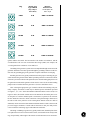
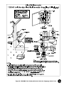
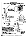
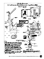
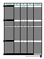
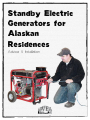
Standby Electric
Generators for
Alaskan
Residences
Advice & Installation
452-1151 • 1-800-770-GVEA • www.gvea.com
Use of this publication is not a substitute for the use of sound judgement by the user. This booklet is intended to provide a useful summary of information, not to provide complete advice suitable for all situations. This booklet is not a substitute for the most
current provisions of the National Electric Code or for the judgement of a licensed electrician. The user is advised to seek out and
obtain the assistance of licensed, qualified persons should any part of the installation/design seem unclear.
Updated 2011
Life in Alaska is exciting and different. No small part of the spice of life here is
the environment: the scenic beauty, the weather, the scale of the natural forces.
Introduction
Floods, earthquakes, severe storms and wildfires are also part of living in Alaska.
Natural disasters create potential emergency situations and power outages can occur.
Even if these events are uncommon, they do happen with some regularity in nearly all
regions of Alaska. Few areas of the state are immune, and emergency preparedness is
a useful response to the threats we face in our Alaskan homes and routines.
Storms, natural disasters, and accidents can and do cause electrical power failures.
Depending on temperature, an outage that lasts longer than six hours can lead to serious problems, such as frozen water pipes, spoiled food and even danger to family,
livestock or pets.
Standby electric power from generators can keep your essential electrical equipment
operational during power outages. This “insurance” can help you avoid inconvenience
and financial loss. This publication is designed to give you current, safe and economical information about installing a standby electrical generator for your home.
Individuals with health care needs that are life-threatening if power is out for an
extended period of time should consider an emergency system designed by a professional engineer and installed by a licensed contractor. The systems described in this
publication do not describe the installation of an emergency system.
To provide the standby power you will need:
1. A 60 Hz (cycle per second) alternating current (AC) generator to provide the
standby electric power at 120-volts or 120/240-volts.
Requirements
2. An engine to run the AC generator. Most off-the-shelf generators are purchased
as a unit with the engine sized for the generator.
3. A transfer switch to provide an easy means of transferring the generator
electrical power to your house electrical wiring. The transfer switch provides
a safe means of transferring standby power, while prohibiting the generator
from being connected to the utility power system.
Typically, homes are served by the utility from a 120/240-volt, single phase transformer and a three wire service. The three wire service consists of two insulated black
wires which have 240-volts between them, and 120-volts between each insulated wire
and the white or bare neutral.
Generators with voltage ratings of 120-volts, 115/230-volts or 120/240-volts can
be used. Generators which are rated only 240-volts output (240-volts between the two
wire output with no neutral) should not be used.
Do not use generators which produce 50 Hz (cycles per second), or direct current (DC).
1
Sizing a
Generator for
Your Needs
Generators are rated not only by their voltage, but also by their power output,
measured in watts or kilowatts – one kilowatt equals 1000 watts. Some generators
may also be rated in volt-amperes or kilovolt-amperes, which are related to watts but
are not the same. You can approximate the power output in watts by multiplying the
volt-ampere rating by 0.8.
The kilowatt, or watt rating is given on the generator nameplate and can also be
listed in the owners manual. Some generators may have a continuous power capacity
in addition to a short term overload capacity. The short term overload capacity is typically a small percentage of the continuous rating. Generators rated for a continuous
rating at 120/240-volts may have a half power rating for 120-volt only use. The rating
is typically reduced in half as only one of the two windings will be used during120volt operation. For example, a generator rated 4000 watts at 120/240-volts may only
be rated 2000 watts at 120-volts. The continuous rating of the generator should be
larger or equal to the total load.
The size of generator you need depends, in part, on whether you will be operating
all or only part of your household equipment at the same time. Most people will try
to economize and size their generator to operate only a portion of their equipment at
one time. To determine the load which will be served by the standby generator, use
the following steps:
1. Decide what equipment you will need to operate during power outages.
Consideration should also be given to additional equipment which you may
want to add to this list later.
2. Verify motor nameplates and electrical demand of all motors or equipment
with internal motors that you wish to operate on the standby generator. Typically the motor currents and voltages are provided on the motor nameplates,
or the device nameplates. To compute the volt-amperes required to run the
motor multiply the voltage times the motor amperes (amps). For example, if
the motor runs on 120-volts and the nameplate on the motor lists the motor
amps at 4.9 amps, the motor will require 588 volt-amperes.
3. Once you have calculated the volt-amperes required to run each motor, you
must compute the starting load of the largest motors which can start at one
time. Motors that can start at one time are considered to be motors that are not
started by hand (switch) operation, such as furnaces, freezers, refrigerators,
and well pumps. Motors require more amperes to start than they require to
run. Typically, when motors are started they require 5 to 6 times the running
current for a short period as the motor spins up to speed. For example, the
previous 120-volt motor, which was rated 4.9 amps on the nameplate, would
require between 24.5 amps and 29.4 amps during starting. Multiplying the
motor voltage by the starting current will yield an equivalent starting load
of 2940 to 3528 volt-amperes during starting.
4. The generator should be sized to supply at least the sum of the following
loads:
a. All non-motor loads.
b. Motor starting loads for all motors which can start at one time.
c. Motor running loads for all remaining motors.
2
5. Check your calculations with your local utility or generator dealer before
you purchase a generator. As most portable generators are rated in watts or
Kw, assume your total load in volt-amperes (from Step 4) equals the total
load in watts (i.e. 5000 VA = 5000 watts)
It is important to note a generator should be purchased with circuit breaker overcurrent protection.
In this publication, we will divide the most probable standby generator sizes into
three power rating groups:
500 - 3000 watts 3000 - 5000 watts
5000 - 15000 watts Range 1
Range 2
Range 3
Range 1 (500 - 3000 watts) is a minimal power supply, and is typically the range
available from small portable, gasoline powered generators. Generators of this size
are typically designed to only provide 120-volt power through extension cord connections. Because of their limited capacity and 120-volt rating they are typically not
suitable for connection to a 120/240-volt service or 120/240-volt emergency panel
transfer switch. The Range 1 generator is suited for connection to an individual circuit
through the application of a transfer switch rated at the branch circuit breaker rating,
typically 15 or 20 amps. Refer to Figures 3 and 4 for information on installation of a
transfer switch into essential branch circuits.
Range 2 (3000 - 5000 watts). This generator range typically has 120/240-volt outputs,
and is suitable for powering essential loads, such as a furnace, oil-fired boiler system,
water pumps and essential lighting circuits. The Range 2 option is more expensive than
the Range 1 option, but has its obvious advantages. Because of the 120/240 voltage
rating, the Range 2 generator can be used to supply emergency panels and entire houses
with smaller electric needs through a 120/240-volt service or 120/240-volt emergency
panel transfer switch. See Figures 1, 2 and 5 for information on the installation of a
two-pole transfer switch to feed an emergency panel or the entire service.
Range 3 (5000 - 15000 watts) is typically considered full load standby for non-electric
heat houses. The voltage rating of this generator must be 120/240-volts to provide the
correct alternate power source voltage to the house. See Figure 1 for an example of how
to install and connect a service transfer switch to switch the entire house load.
The transfer switch is an essential part of the standby electric power equipment.
The National Electric Code (NEC) and electric power suppliers require a standby
generator be properly connected to the electric system with a transfer switch to prevent
any interconnection of the generator and the utility supply. If this isolation is not supplied, the generator power can back feed the service and transformer and energize the
power-line, creating a hazard to personnel working on the lines. The transfer switch
also prevents your standby generator from being damaged or destroyed, when utility
power is restored.
The Transfer
Switch
For transferring of 120-volt loads, a single-pole transfer switch is required. For
transferring of 120/240-volt loads, a two-pole transfer switch is required.
The transfer switch must be rated according to the size of the protective device
serving the load. For example, if the transfer switch will be installed in a 100-amp
3
service, a 100-amp two-pole transfer switch will be required. If the transfer switch
only transfers an emergency panel served from a 60-amp breaker, a 60-amp two-pole
transfer switch will be required. If the transfer switch is for a 20-amp 120-volt branch
circuit, then only a 20-amp single-pole transfer switch will be required.
The transfer switch must also be rated for the available fault current. Fault current
can be computed, and is the amount of current, in amperes, which will flow through
the switch if two of the service wires are inadvertantly connected together. Typically,
the larger the service transformer and the wire size, the larger the fault current. Most
service breakers are rated at least 10,000 amperes interrupting current (AIC). As a
rule of thumb, the transfer switch should have an AIC rating of at least as much as
the main service breaker. The utility can easily compute the available fault current if
the size of the transformer, and wire size and length are known.
Automatic transfer switches are available but are mainly used for highly reliable,
permanently wired, standby systems with automatically starting generators. Typically,
manual start generators and manual transfer switches are used for homes.
Installation
Wiring and equipment must be correctly installed to meet current National Electric Code, federal, state and local codes and requirements of the local power supplier.
Inspection by the state or utility of the installation may be required in certain areas,
and is certainly recommended.
If during the connection of the transfer switch additional wire is needed, it should
be of the same material, size and insulation type as the existing wire. For example, if a
transfer switch is being installed for a 100-amp service, which has #2 American Wire
Gauge (AWG) copper conductor with Type XHHW insulation, any additional wire
needed for the main circuit conductors should be the same. The wire size, material and
insulation type will be marked on the outside of the insulation. Alternate insulation
type can be found in the National Electric Code.
Connection to the portable generator can typically be made with a flexible cord and
connector. The correct wire size of flexible cord can be found in the National Electric
Code, Article 400. A longer cable may require a larger wire size than that listed by
NEC Article 400. This is due to the increased voltage drop across the longer cable. All
120-volt systems shall use a three conductor flexible cord, one for the hot phase, one
for the neutral and one for a grounding conductor to attach the generator to the house
grounding system. All 120/240-volt systems shall use a four conductor flexible cord,
one for each 120-volt phase, one for the neutral and one for a grounding conductor to
attach the generator to the house grounding system. In many instances, members will
fabricate their own cord/connector assembly. It is very important to connect the correct
conductor to the correct plug terminal. The white insulated (neutral) conductor is connected to the silver terminal, the black or red insulated (phase) conductor is connected
to the bronze terminal, and the green or bare conductor is connected to the green Hex
terminal. It is extremely important to install all cords and connectors with the correct
polarity. The generator and building connector will typically be a 5-20R, L5-20R, or
a L5-30R for 120 volt circuits. The 120/240-volt circuits typically use a L14-20R or
L14-30R. The last number designates the ampere rating of the plug, and the L designates
twist locking. An L5-30R plug is a locking plug that is rated 30 amperes.
4
Several flexible cords are available. The Type SJE used in the example above
is rated 105oC (221oF), and has the added rating of -50oC (-58oF), and the W-A des-
Plug
Flexible Cord
Type SJEW-A
Maximum
Generator Size
[-50oC (-58oF) to 105oC (221oF)]
(in volt-amperes VA,
watts @ .8 pf)
5-20R
3/12
2400 VA, 1920 W
L5-20R
3/12
2400 VA, 1920 W
L5-30R
3/10
3600 VA, 2880 W
L14-20R
4/12
4800 VA, 3840 W
L14-30R
4/10
7200 VA, 5760 W
ignates outdoor rated cable. The first number is the number of conductors, and the
second number is the wire size in American Wire Gauge (AWG). For example, the
3/12 designates three conductors of #12 AWG size.
Grounding of the generator system can be accomplished through connection of the
generator and frame to the house ground through the grounding conductor in the flexible cord, the grounding plug in the generator receptacle and transfer switch plug.
Portable generators are typically manufactured with a jumper connecting the generator neutral to the generator frame. When a portable generator is connected to a home
electrical system as described in this publication, the neutral bonding jumper between
the generator neutral and the generator frame must be removed. The neutral bonding
jumper must be installed when the generator is used as a stand-alone source.
After selecting the appropriate type of transfer scheme and consulting with your
utility company, the transfer switch may be installed per the information provided
on Figures 1, 2, 3, 4 or 5. If the GEN/TRAN residential transfer switch is used, as in
Figures 4 and 5, the flexible conduit must not be attached to the breaker panel cover
for the panel. If a surface mounted panel is encountered, a portion of the wall near
the box should be removed to allow connection to the panel through a knockout on
the side or back of the panel box. If the existing house branch circuits are made of
aluminum, do not connect the GEN/TRAN residential transfer switch as shown to the
pre-wired copper conductors. Consult with an electrician or with your utility for the
correct method of connecting copper and aluminum conductors.
The Range 1 and Range 2 generators, typically mobile units, should be placed on a
level pad within 10 to 20 feet of the transfer switch, a safe distance from nearby buildings, and preferably within sight of the transfer switch and main service disconnect.
5
Range 3 generators may be designed as mobile units or for permanent mounting. All
generators should be mounted per the manufacturer’s recommendations. Permanently
mounted generators can be mounted on a reinforced concrete base at least 6 inches
(15 cm) thick. Anchor bolts can be used to attach the generator to the concrete pad.
If the standby unit is permanently installed indoors, be sure the ventilation is
adequate. Air inlets and outlets should each be open at least half a square-foot (0.046
m2) for each kilowatt of generator capacity. Exhaust fumes must be vented to the
outside; you can use an exhaust-pipe extension of flexible metal tubing. Check with
your generator manufacturer as altering the exhaust system may void the warranty. If
allowed, keep the additional pipe as short as possible to reduce back pressure on the
engine. The engine’s exhaust pipe and connecting tubing must be at least 6 inches
(15cm) from combustible material, because the exhaust pipe becomes quite hot during operation. The engine of a 5 kilowatt generator produces almost as much heat as
a house furnace.
The generator should be installed at a location to minimize the risk of fire to structures. Many portable generators have the fuel tank mounted to the generator frame
above the engine/generator. If a fuel leak develops or the engine/generator overheats,
a fire could occur. Installing the generator at a safe distance away from buildings and
structures will reduce the chance of a house fire.
A permanent sign should be installed at the service entrance equipment or near
the main disconnect/meter location which states that a generator can be connected to
this system for standby power.
If the standby unit is permanently installed outdoors, shelter it from the weather. Do
not cover with moisture-holding plastic sheeting. The shelter must be well ventilated
and permit easy access to the equipment. Protect the engine cooling systems from
fine blowing snow, dust or other material that can block the air intake or exhaust gas
pipes. Cover all generator openings with 1/4 inch (0.6 cm) galvanized wire mesh to
prevent damage by rats, shrews, voles or mice. Clean the mesh of obstructions and
dust that will restrict airflow through the generator.
Operation
Use your manufacturer’s manual. Study and follow the instructions for running
your equipment.
The installations in this handout cover the operations procedure for manually
controlled generators and transfer switches. In the event of an outage:
1. Call your utility and report the power failure.
2. Turn off or disconnect all electric equipment.
3. Place the generator in position.
4. Remove the neutral grounding jumper, if installed.
5. Check engine oil and fuel level.
6. Start the generator engine. If required, bring the generator up to proper
speed.
6
7. If required, check the voltage and frequency. The voltmeter should register at
least 230 volts for 120/240-volt services, or 115 volts for 120-volt service. The
frequency should be 60 hertz plus or minus 2 hertz. Do not increase generator
speed to more than the nameplate under normal load to raise the voltage. It
will not increase the electric power output, and it can cause problems with
your motors and other frequency sensitive equipment, such as clocks.
8. Put the transfer switch in the generator position.
9. Connect the electric load. Start the largest motor first, adding other loads
when each successive motor reaches its full operating speed. Do not add the
loads too quickly. If the generator stops, repeat steps 2, 5, 6, 7 and 8.
10. Check the voltage often to make sure you are not overloading the generator.
If voltage falls below 220 volts for 120/240-volt service, or 110 volts for 120volt service, turn off some of the electric equipment to reduce the load.
11. When regular power is restored, switch the transfer switch into the regular
utility power source’s position. Then stop the standby generator. Turn on
electric loads as usual. The transfer switch should be used to switch load
from the generator. DO NOT USE THE FLEXIBLE CORD CONNECTOR
TO REMOVE OR DISCONNECT LOAD FROM THE GENERATOR.
Removing the flexible cord connector from a loaded generator can cause
damage to the connector and/or electric shock.
12. Re-install the neutral grounding jumper to allow the generator to be used as
a stand-alone power source.
Follow the instructions in your generator manufacturer’s manual. Test operate
the generator unit – under load – at least once a month. Check for fuel leaks. Replace
or use the fuel supply periodically to prevent moisture condensation in the tank, gum
accumulation in the carburetor or fuel deterioration – loss of the volatile components.
Consider using a “fuel stabilizer” if recommended by the generator manufacturer.
Maintenance
These guidelines are not intended as a complete installation guide for all generators and transfer switches, or to relieve the user of meeting the National Electric Code,
applicable state or local ordinances or codes.
Precautions
If questions arise in the application of this guideline, contact your electric utility, a
licensed electrical engineer, local or state inspector, or a licensed electrical contractor
for clarification and application of local ordinances and codes, to guarantee a reliable,
safe and economic installation.
The configurations illustrated by Figures 1, 2, 3, 4 and 5 will require some reworking or restructuring of the electrical service into your house. Consult with an
electrician or with your utility if you have any questions, unless you are familiar with
the requirements of the National Electrical Code applicable to these situations.
•
Test your standby generator in advance, before an emergency occurs, to make
sure it works and to familiarize yourself with the procedure.
•
If wiring has been damaged or is defective, don’t use your standby generator
until you remove the defective circuit from the system.
•
If wind, ice or an accident caused the power outage, your home wiring may
need to be repaired before you use the standby generator.
•
Keep flashlights or lanterns handy so you have light if you need it.
•
Do not fuel the generator while the generator is running, or if it is hot. Allow
the generator to cool before refueling.
7
8
Figure 1: 120/240 Volt Standby Electrical Generator Supplying Total Load
Figure 2: 120/240 Volt Standby Electrical Generator Supplying Critical Load
9
10
Figure 3: 120 Volt Standby Electrical Generator Supplying Single Branch Circuit
Figure 4: 120 Volt Standby Electrical Generator Supplying Multiple Branch Circuits
11
12
Figure 5: 120/240 Volt Standby Electric Generator Supplying Multiple Branch Circuits
Kind of Equipment
Horsepower
(Hp)
Running Watts
(W)
Essential
Lighting
Refrigerator
1/4 - 1/2
Freezer
1/4 - 1/2
Furnace, stoker
1/4
Furnace, oil burner
1/6
Furnace, hot water circ pump
1/6 - 1/4
Furnace, blower
1/4 - 1/2
Hot water heater - electric
Portable electric heater
Microwave oven
Car headbolt heater
Well pump
Water pump
1/2 - 2
800 - 2500
Optional
Toaster
Mixer
Coffeemaker
Electric iron
Electric range
Electric clothes dryer - blower
1/6
Electric clothes dryer - heater
Window air conditioner
1/2 - 2
Central air
2 - 5
Electric fan
Water heater
Kitchen ventilator
Television
Nintendo
Dishwasher - wash only
1/6
Dishwasher - heater
Washing machine
1/4 - 1/2
Sewing machine
Sweeper
1/4
1200 - 1500
150
1000 - 1500
500 - 1500
3000 - 10,000
500
4000
1000 - 2000
2000 - 5000
75 - 300
1000 - 5000
150
200 - 600
20
300
1500
400
200 - 500
400 - 1500
100-2000
400-800
600-1000
400
300
300 - 400
400-600
4500
600 - 1500
800 - 1600
600 - 1500
Starting Watts
(W)
Total Load to be run
on the Generator
1200-2300
1200-2300
1200
1000
1000 - 1200
1200-2300
2300 - 8000
1000
2300 - 8000
8000 - 18,000
1000
1200 - 2300
1200
Motors
1/6
1/4
1/3
1/2
3/4
1
1 1/2
2
3
5
7 1/2
10
215
300
400
575
835
1000
1500
2000
3000
4500
7000
9000
1000
1200
1600
2300
3345
4000
6000
8000
12,000
18,000
28,000
36,000
Total
Figure 6: Typical Appliance Ratings
13