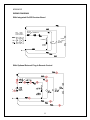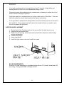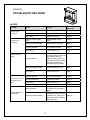
1
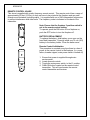
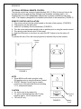
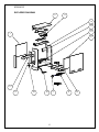
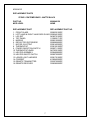
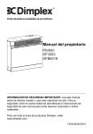
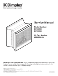
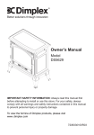
CONTEMPRA
MODEL KDS6401E
PARTS & SERVICE MANUAL
7400060000R02
Table of Contents
OPERATION ............................................................................................................................. 2 MAINTENANCE ........................................................................................................................ 5 EXPLODED DIAGRAM ............................................................................................................. 6 REPLACEMENT PARTS ........................................................................................................... 7 WIRING DIAGRAM ................................................................................................................... 8 LIGHT BULB REPLACEMENT .................................................................................................. 9 TO REPLACE MAIN ON/OFF SWITCH .................................................................................. 10 TO REPLACE FLAME MOTOR/FLAME ROD ......................................................................... 11 TO REPLACE HEATER ON/OFF SWITCH ............................................................................. 12 TO REPLACE HEATER THERMOSTAT ................................................................................. 13 TO REPLACE POWER CORD ................................................................................................ 14 TO REPLACE THE HEATER ASSEMBLY .............................................................................. 15 TROUBLESHOOTING GUIDE ................................................................................................ 16 GENERAL ............................................................................................................................ 16 APPEARANCE .................................................................................................................... 16 HEATER .............................................................................................................................. 17 NOISE .................................................................................................................................. 18 1
KDS6401E
OPERATION
To access the controls go to the front panel of the unit (refer to diagram below)
1. Three position ON/OFF switch
The switch has two ON positions marked with “-“ and “=”. The “-“ position is for manual
operation. In this position the built-in remote control is bypassed. The “=” position is for
operating the unit with the provided remote control. When in “=” position the unit is operated
with the ON and OFF buttons of the remote control. When the switch is in the center position
the unit is off.
2. HEATER ON/OFF SWITCH
The HEATER ON/OFF SWITCH supplies power to the heater fan and the heater element
and must be turned on before heat can be created.
3. HEATER THERMOSTAT CONTROL
To adjust the temperature to your individual requirements, turn the heater thermostat control
knob clockwise all the way to turn on the heater. When the room reached the desired
temperature, turn the thermostat knob counter clockwise until you hear a click. Leave in this
position to maintain the room temperature at this setting. For additional heat, turn clockwise
until you hear the click again and the heater will turn on. To turn the heater off, switch the
HEATER ON/OFF SWITCH to the OFF position.
NOTE: When the heater is switched ON, the heater fan will operate. The heater element may
or may not be on, depending on the thermostat control setting (SEE “HEATER THERMOSTAT
CONTROL”).
RESETTING THE TEMPERATURE CUTOFF SWITCH
This unit is equipped with a thermostat that controls the temperature of the room. It
does this by turning the heater on and off. The heater is protected with a safety device
to prevent overheating. Should the heater overheat, an automatic cut out will turn the
heater off and it will not come back on without being reset. To reset the temperature
cut-off switch turn the main power switch to the OFF position and wait five minutes
before switching the unit back on.
CAUTION
If you need to continuously reset the heater, unplug the unit and call Dimplex North
America Limited at 1-800-668-6663.
2
KDS6401E
REMOTE CONTROL USAGE
This stove is supplied with a radio frequency remote control. This remote control has a range of
approximately 50 feet (15.25m); it does not have to be pointed at the fireplace and can pass
through most obstacles (including walls). It is supplied with one of 243 independent frequencies
to prevent interference with other units. The frequency code is indicated on the back of the
transmitter.
Note: Ensure that the fireplace 3 position switch is
set to the remote control setting.
To operate, push the ON button to turn fireplace on,
push the OFF button to turn the fireplace off.
BATTERY REPLACEMENT
To replace the battery, slide battery cover open on the
hand held transmitter. Correctly install one 12 volt (A23)
battery in the battery holder. Close the batter cover.
Remote Control Initialization
This procedure is required every time there is a loss of
power to the remote control in the fireplace. (I.e. power
failure, breaker tripped, main power switch is turned off)
1. Ensure that power is supplied through main
service panel.
2. Locate manual controls.
3. Toggle the main power switch, to the“=” position.
4. Press ON button located on the remote control
transmitter. This will synchronize the remote
control transmitter and receiver.
3
KDS6401E
OPTIONAL EXTERNAL REMOTE CONTROL
The remote control has a range of approximately 50ft. (15.25m) it does not have to be
pointed at the stove and can pass through most obstacles (including walls). It is
supplied with one of 243 independent frequencies to prevent interference with other
units. The frequency designation is indicated on the back of the transmitter (FIGURE 3)
REMOTE CONTROL INSTALLATION
1. Plug stove cord set into the outlet located on the side of the receiver. (FIGURE 2)
2. Plug receiver into the wall outlet.
3. Install a 9 volt battery into the transmitter. (FIGURE 3)
4. Turn the stove main power switch to the on position prior to using the remote control.
5. The remote control works up to 50 feet away.
6. Push the ON button to turn stove on, push the OFF button to turn the stove off.
NOTE
To prevent the risk of fire, the stove plug must be inserted fully into the receiver.
Receiver
Outlet
FIGURE 2
NOTE
• Stove MAIN on/off switch must be in the
ON position prior to using the Remote Control.
• ON/OFF Remote Control may be used to
control most other electrical devices including
T.V.’s, stereos and lamps.
CAUTION
• For indoor use in dry areas only
• For use on electrical devices with 15 amp
resistive load or 1/3 HP inductive load
• 120 volt AC only
OPEN
Frequency
Code
FIGURE 3
4
Battery
Cover
KDS6401E
MAINTENANCE
LIGHT BULB REPLACEMENT
Allow at least 5 minutes for light bulbs to cool off before touching bulbs to avoid accidental
burning of skin.
Light bulbs need to be replaced when you notice a dark section of the flame or when the
clarity and detail of the log exterior disappears. There are two bulbs under the log set
which generate the flames and embers.
TO REPLACE THE LIGHT BULBS
1. On the back of the Contempra® remove the screws from the light access cover.
2. Remove the light access cover.
3. Reach into the opening, locate and examine the bulbs to determine which bulb(s)
required replacement.
4. Unscrew the bulb(s) counter clockwise.
5. Insert new bulb(s).
6. Install the light access cover and install the screws
HELPFUL HINTS
It is a good idea to replace all light bulbs at one time if they are close to the end of their
rated life. Group replacement will reduce the number of times you need to open the unit
to replace light bulbs.
BULB REQUIREMENTS
Quantity of 2 clear chandelier or candelabra bulbs with an E-12 (small) socket base, 60
watt rating. Example GE 60BC of Philips 60 CTC.
GLASS CLEANING
The glass is cleaned in the factory during the assembly operation. During shipment,
installation, handling, etc., the glass surface may collect dust particles; these can be
removed by buffing lightly with a clean dry cloth.
To remove fingerprints or other marks, the glass can be cleaned with a damp cloth using
a good quality household glass cleaner. The glass should be completely dried with a lint
free cloth or paper towel. Do not use abrasive cleaners on glass surface or spray liquids
directly onto any surface.
Contempra® SURFACE CLEANING
Use warm water only to clean painted surfaces of the Contempra®. Do not use abrasive
cleaners on surface or spray liquids directly onto any surface.
5
KDS6401E
EXPLODED DIAGRAM
4
11
12
9
8
1
5
3
2
10
14
7
6
6
13
KDS6401E
REPLACEMENT PARTS
STOVE- CONTEMPORARY - MATTE BLACK
PART NO.
MOD LEVEL
6900940159
NONE
REPLACEMENT PART
REPLACEMENT PART NO.
1. FRONT GLASS
5900230100RP
2. LEFT HAND & RIGHT HAND SIDE GLASS 5900240100RP
3. LOG SET
0438270100RP
4. TOP PANEL
1103820171RP
5. MIRROR
5900210200RP
6. REFLECTOR ROTISSIERE
5900080600RP
7. MOTOR, ELECTRIC
2000140300RP
8. THERMOSTAT
2300150100RP*
9. POWER ON/OFF/ON SWITCH
2800071100RP
10. THERMOSTAT KNOB
0437930159RP
11. HEATER ASSEMBLY
2200490900RP
12. HEATER ON/OFF SWITCH
2800070200RP
13. LOWER LIGHT HARNESS
2500170100RP
14. CORDSET
4100040300RP
15. REMOTE TRANSMITTER
3000370500RP
16. REMOTE RECEIVER
3000380200RP
7
KDS6401E
WIRING DIAGRAM
With Integrated On/Off Receiver Board
On/Off
Main
On/Off Integral
Switch Receiver
HEATER
ON/OFF
THERMOSTAT
C
ELEMENT
FAN
MOTOR
LOWER
A.C. LIGHTS
FLICKER
MOTOR
C
THERMAL
CUTOUT
N
With Optional External Plug-In Remote Control
C
L
C
N
8
KDS6401E
If unit was operating prior to servicing allow at least 10 minutes for light bulbs and
heating element to cool off to avoid accidental burning of skin.
Disconnect power before attempting any maintenance or cleaning to reduce the risk of
electric shock or damage to persons.
Light bulbs need to be replaced when you notice a dark section of the flame. There are
two bulbs under the log set which generate the flames and embers.
It is a good idea to replace all of the light bulbs at one time if they are close to the end of
their rated life. Group replacement will reduce the number of times you need to open
the unit to replace the light bulbs.
LIGHT BULB REPLACEMENT
1. On the back of the Contempra remove the screws from the light access cover.
2. Remove the light access cover.
3. Reach into the opening, locate and examine the bulbs to determine which bulb(s)
require replacement.
4. Unscrew the bulb(s).
5. Insert new bulb(s).
6. Install the light access cover and install the screws
BULB REQUIREMENTS
Quantity of 2 clear chandelier or candelabra bulbs with an E-12 (small) socket base, 60
watt rating. Example GE 60BC of Philips 60 CTC.
9
KDS6401E
If the stove was operating prior to servicing allow at least 10 minutes for light bulbs and
heating element to cool off to avoid accidental burning of skin.
Disconnect power before attempting any maintenance or cleaning to reduce the risk of
electric shock or damage to persons.
TO REPLACE MAIN ON/OFF SWITCH
1. Remove the stove pipe kit (if equipped).
2. Remove the four screws from the rear panel and remove.
3. Locate the main on/off switch mounted to the top panel and disconnect the wiring
clips and connections noting their original locations.
4. Depress the retainer clips on the rear of the switch and push the switch down and
out of the top cover.
5. Properly orientate the new switch and connect all of the wiring clips and
connections.
6. Reassemble in the reverse order as above.
10
KDS6401E
If the stove was operating prior to servicing allow at least 10 minutes for light bulbs and
heating element to cool off to avoid accidental burning of skin.
Disconnect power before attempting any maintenance or cleaning to reduce the risk of
electric shock or damage to persons.
TO REPLACE FLAME MOTOR/FLAME ROD
1. Remove the stove pipe kit (if equipped).
2. Remove the four screws from the rear panel and remove.
3. Locate the flame motor and flame rod assembly, remove the motor mounting screws
with a short handled screw driver.
4. Locate and remove the wiring connections and remove the flame rod and flame
motor assembly.
NOTE: When removing the flame motor some damage may occur to the flame rod.
If flame rod is damaged replace to insure proper operation.
5. To remove the flame rod attach needle nose pliers to the spring on the motor shaft
and pull while rotating in the opposite direction of the spring winding.
6. To replace the flame rod attach needle nose pliers to the flame rod spring and push
onto the flame motor shaft while rotating in the opposite direction of the spring
winding.
7. Properly orientate the flame motor and connect all of the wiring clips connections in
their original locations.
11
KDS6401E
If the stove was operating prior to servicing allow at least 10 minutes for light bulbs and
heating element to cool off to avoid accidental burning of skin.
Disconnect power before attempting any maintenance or cleaning to reduce the risk of
electric shock or damage to persons.
TO REPLACE HEATER ON/OFF SWITCH
1. Remove the stove pipe kit (if equipped).
2. Remove the four screws from the rear panel and remove.
3. Locate the heater on/off switch mounted to the top panel and disconnect the wiring
clips and connections noting their original locations.
4. Depress the retainer clips on the rear of the switch and push the switch down and
out of the top cover.
5. Properly orientate the new switch and connect all of the wiring clips and
connections.
6. Reassemble in the reverse order as above.
12
KDS6401E
If the stove was operating prior to servicing allow at least 10 minutes for light bulbs and
heating element to cool off to avoid accidental burning of skin.
Disconnect power before attempting any maintenance or cleaning to reduce the risk of
electric shock or damage to persons.
TO REPLACE HEATER THERMOSTAT
1. Remove the stove pipe kit (if equipped).
2. Remove the four screws from the rear panel and remove.
3. Locate the heater thermostat mounted on the rear panel and disconnect the wiring
clips and connections noting their original locations.
4. Pull off the thermostat control knob to expose the mounting screws.
5. Remove the mounting screws and remove the heater thermostat.
6. Reassembly in the reverse order as above.
13
KDS6401E
If the stove was operating prior to servicing allow at least 10 minutes for light bulbs and
heating element to cool off to avoid accidental burning of skin.
Disconnect power before attempting any maintenance or cleaning to reduce the risk of
electric shock or damage to persons.
TO REPLACE POWER CORD
1. Remove the stove pipe kit (if equipped).
2. Remove the four screws from the rear panel and remove.
3. Locate and remove the wiring connections for the power cord.
4. With needle nose pliers grasp the power cord strain relief grommet from inside the
bottom cover and push while twisting to remove.
5. Pull the old power cord out through the bottom cover.
6. Install the new power cord through the hole in the bottom cover and connect all of
the wiring connections in their original locations.
7. Install the power cord retaining grommet on the power cord and insert into the hole
in the bottom cover.
8. Reassemble in the reverse order as above.
14
KDS6401E
If the stove was operating prior to servicing allow at least 10 minutes for light bulbs and
heating element to cool off to avoid accidental burning of skin.
Disconnect power before attempting any maintenance or cleaning to reduce the risk of
electric shock or damage to persons.
TO REPLACE THE HEATER ASSEMBLY
1. Remove the stove pipe kit (if equipped).
2. Remove the four screws from the rear panel and remove.
3. Locate and remove the four screws on the inner heater panel.
4. Locate the eight cam locks on the side and front panels inside the upper corners of
the stove and turn with a large slot screwdriver so the triangle on the cam lock is
pointing up towards the top of the stove.
5. Grasp the top at both sides and gently pull to release the top.
6. Remove the heater mounting screws.
7. Disconnect the wiring clips and connections noting their original locations and remove
the heater assembly.
8. Properly orientate the replacement heater assembly and connect all of the wiring clips
connections in their original locations.
9. Reassemble in the reverse order as above.
15
KDS6401E
TROUBLESHOOTING GUIDE
GENERAL
Problem
Cause
Solution
Improper circuit current rating
Additional appliances may
exceed the current rating of
the circuit breaker or fuse.
Plug unit into another outlet
or install unit on a dedicated
15 amp circuit
Optional remote control has a
similar frequency to other
remotes in the area
Radio frequency disturbance
from outside sources
Replace hand held remote
control
Lights dim in room
while the unit is on
Unit is drawing close to circuit
current rating
Move the unit to another
outlet or install unit on a
dedicated 15 amp circuit
Power cord gets
warm
Normal operation
Circuit breaker trips
or fuse blows when
unit is turned on
Unit turns on or off
by itself
Service Manual
Reference
Defective power cord
The power cord may get
slightly warm to the touch
when the heater is on
Replace power cord
Cause
Solution
Improper operation
Refer to User’s Guide
Defective main On/Off switch
Replace main On/Off switch
Defective optional remote
control
Install new battery into the
handheld transmitter
Defective Remote Receiver
Replace Remote Receiver
Loose wiring
Check wiring connections
Page 7
Defective flame motor
Replace flame motor
Page 10
Loose wiring
Check wiring connections
Page 7
Burnt light bulbs
Replace light bulbs
Page 8
Loose wiring
Check wiring connections
Page 7
Defective light harness
Replace light harness
Log set dim, ember
bed not glowing
Burnt light bulbs
Replace light bulbs
Page 8
Flame Shutter
Defective flame motor
Replace flame motor
Page 10
Page 13
APPEARANCE
Problem
Stove does not turn
on
Flame frozen
Flame not bright or
flame not visible
16
Service Manual
Reference
Page 11
KDS6401E
TROUBLESHOOTING GUIDE
HEATER
Problem
Heater is not
turning off
Heater is not
turning on
Cause
Solution
Service Manual
Reference
Defective heater on/off switch
Replace heater on/off switch
Page 11
Improper operation
See Operation Section
Page 2
Loose wiring
Trace wiring in unit
Page 7
Defective heater On/Off
switch
Replace heater On/Off
switch
Page 11
Defective heater assembly
Replace heater assembly
Page 14
Improper operation
See Operation Section
Page 2
Loose wiring
Trace wiring in unit
Page 7
Normal operation
Normal operation is when
the heater emits an odour for
a brief period after the
heater is initially turned on.
The heater is burning off any
dust accumulated during
manufacturing or operation.
Defective heater assembly
Replace heater assembly
Page 14
Loose wiring
Trace wiring in unit
Page 7
Improper operation
See Operation Section
Page 2
Defective thermostat
Replace thermostat
Page 12
Loose wiring
Trace wiring in unit
Page 7
Defective heater assembly
Replace heater assembly
Small glowing sections of
the element are considered
normal.
If larger glowing sections are
causing the heater to trip the
thermal cut out, unplug unit,
discontinue use and replace
heater assembly
Page 14
Heater emits an
odour
Heater fan turns on
but heater lacks
heat
Normal operation
Heating element is
glowing red
Defective heater assembly
17
Page 14
KDS6401E
TROUBLESHOOTING GUIDE
HEATER (CONTINUED)
Problem Heater fan runs
continuously
Cause Solution
Service Manual
Reference
Loose wiring
Trace wiring in unit
Page 7
Defective heater On/Off
switch
Replace heater On/Off
switch
Page 11
Defective heater assembly
Replace heater assembly
Page 14
Cause
Solution
Service Manual
Reference
Dirty blower assembly
Clean blower assembly
Defective blower assembly
Replace heater assembly
Page 14
Moving flame rod hitting or
rubbing against internal
components
Flame rod replacement
Page 10
Defective flame motor
Replace flame motor
Page 10
NOISE
Problem
Excessive noise
with the heater on
Grinding or
excessive noise
with the heater off
18