1
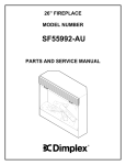
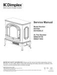
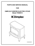
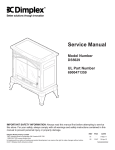
Service Manual
Model Numbers:
DS5598
DS5603
DS5804
SS5800PB
SS5858N
Dimplex North America Limited
1367 Industrial Road Cambridge ON Canada N1R 7G8
1-888-346-7539 www.dimplex.com
In keeping with our policy of continuous product development, we reserve the right to make changes without notice.
© 2013 Dimplex North America Limited
7400650000R04
Table of Contents
Operation. . . . . . . . . . . . . . . . . . . . . . . . . . . . . . . . . . . . . . . . . . . . . . . . . . . . . . . . . . . 3
Maintenance. . . . . . . . . . . . . . . . . . . . . . . . . . . . . . . . . . . . . . . . . . . . . . . . . . . . . . . . . 4
Exploded Parts Diagram. . . . . . . . . . . . . . . . . . . . . . . . . . . . . . . . . . . . . . . . . . . . . . . 5
Replacement Parts List. . . . . . . . . . . . . . . . . . . . . . . . . . . . . . . . . . . . . . . . . . . . . . . . 6
DS5598, SS5800PB, SS5858N . . . . . . . . . . . . . . . . . . . . . . . . . . . . . . . . . . . . . . . . . . . . . . . . . . . 6
DS5603, DS5804 . . . . . . . . . . . . . . . . . . . . . . . . . . . . . . . . . . . . . . . . . . . . . . . . . . . . . . . . . . . . . . 6
Wiring Diagram . . . . . . . . . . . . . . . . . . . . . . . . . . . . . . . . . . . . . . . . . . . . . . . . . . . . . . 7
DS5598 Mod 0. . . . . . . . . . . . . . . . . . . . . . . . . . . . . . . . . . . . . . . . . . . . . . . . . . . . . . . . . . . . . . . . 7
DS5598 Mod A-E, SS5800PB, SS5858N, DS5603 Mod 0-E, DS5804 Mod 0-E. . . . . . . . . . . . . . 7
DS5603 Mod G, DS5804 Mod G. . . . . . . . . . . . . . . . . . . . . . . . . . . . . . . . . . . . . . . . . . . . . . . . . . 7
Main On/Off Switch Replacement . . . . . . . . . . . . . . . . . . . . . . . . . . . . . . . . . . . . . . . 8
Heater On/Off Switch Replacement. . . . . . . . . . . . . . . . . . . . . . . . . . . . . . . . . . . . . . 8
Thermostat Replacement. . . . . . . . . . . . . . . . . . . . . . . . . . . . . . . . . . . . . . . . . . . . . . 8
Flicker Motor/Flicker Rod Replacement . . . . . . . . . . . . . . . . . . . . . . . . . . . . . . . . . . 8
Heater Assembly Replacement . . . . . . . . . . . . . . . . . . . . . . . . . . . . . . . . . . . . . . . . . 9
Mod 0-B . . . . . . . . . . . . . . . . . . . . . . . . . . . . . . . . . . . . . . . . . . . . . . . . . . . . . . . . . . . . . . . . . . . . . 9
Mod C and Higher. . . . . . . . . . . . . . . . . . . . . . . . . . . . . . . . . . . . . . . . . . . . . . . . . . . . . . . . . . . . . 9
Power Cord Replacement. . . . . . . . . . . . . . . . . . . . . . . . . . . . . . . . . . . . . . . . . . . . . 10
Mod 0-B . . . . . . . . . . . . . . . . . . . . . . . . . . . . . . . . . . . . . . . . . . . . . . . . . . . . . . . . . . . . . . . . . . . . 10
Mod C and Higher. . . . . . . . . . . . . . . . . . . . . . . . . . . . . . . . . . . . . . . . . . . . . . . . . . . . . . . . . . . . 10
Troubleshooting Guide. . . . . . . . . . . . . . . . . . . . . . . . . . . . . . . . . . . . . . . . . . . . . . . 12
2
Operation
The “=” position is for operating the unit with the provided
remote control. When in “=” position the unit is operated with
the ON and OFF buttons of the remote control.
When the switch is in the center position the unit is off.
To access the controls go to the back of the Stove, depending on the model the controls will be like Figure 1 or 2.
Figure 1
B.
Heater On/Off Switch
The Heater On/Off Switch supplies power to the heater fan
and the heater element.
C. Heater Thermostat Control
To adjust the temperature to your individual requirements,
turn the thermostat control clockwise all the way to turn on
the heater. When the room reached the desired temperature,
turn the thermostat knob counter clockwise until you hear a
click. Leave in this position to maintain the room temperature
at this setting. For additional heat, turn clockwise until you
hear the click again and the heater will turn on. To turn the
heater off, switch the Heater On/Off Switch to the Off position.
! NOTE: When the heater is switched On, the heater fan
will operate. The heater element may or may not be on, depending on the thermostat control setting.
A
C
B
Figure 1 Controls
A. Main On/Off Switch
The on/off switch supplies power to all unit functions (heat
and flame)
B. Heater On/Off Switch
The Heater On/Off Switch supplies power to the heater fan
and the heater element.
C. Heater Thermostat Control
To adjust the temperature to your individual requirements,
turn the thermostat control clockwise all the way to turn on
the heater. When the room reached the desired temperature,
turn the thermostat knob counter clockwise until you hear a
click. Leave in this position to maintain the room temperature at this setting. For additional heat, turn clockwise until
you hear the click again and the heater will turn on. To turn
the heater off, switch the Heater On/Off Switch to the OFF
position.
! NOTE: When the heater is switched ON, the heater fan
will operate. The heater element may or may not be on,
depending on the thermostat control setting (SEE “HEATER
THERMOSTAT CONTROL”).
Resetting The Temperature Cutoff Switch
Should the heater overheat, an automatic cut out will turn the
heater off and it will not come back on without being reset. It
can be reset by switching the Main On/Off Switch to Off and
waiting 5 minutes before switching the unit back on.
CAUTION: If you need to continuously reset the heater,
unplug the unit and call Dimplex North America Limited at
1-888-346-7539.
Remote Control (Figure 2)
The stove is supplied with an integrated On/Off remote control, that is factory syncronized with the stove.
To operate, push the ON button to turn stove on, push the
OFF button to turn the stove off. The amount of heat produced will be dependant on positioning of manual heat
controls.
! NOTE: Ensure that the stove’s On/Off switch is set to the
remote control setting (“ II ” position).
Figure 2 Controls
A. Three Position On/Off Switch
The switch has two On positions marked with “-” and “=”.
The “-” position is for manual operation. In this position, the
built-in remote control is bypassed.
Initialization/Reprogramming
Follow these steps for remote control initialization if required:
①Set the main power switch to OFF.
Figure 3
Figure 2
A
On
Button
C
Battery
B
Off
Button
Battery
Cover
3
②Set the 3 Position Switch to the Remote position (refer to
Operation Section).
2.
③Wait a minimum of five (5) seconds and then turn the
3.
4.
5.
main power ON.
④Within 10 seconds of re-acquiring power, press the ON
button located on the remote control.
! NOTE: You will have only 10 seconds to perform this last
step. Failure to do so will result in these steps needing to
be followed again.
This will synchronize the remote control and receiver.
6.
remove the log set from the unit.
Locate and examine the bulbs to determine which bulb(s)
required replacement.
Locate and remove the light bulb(s).
Insert new bulb(s).
Install the log set into the unit, pushing firmly against the
glass. Replace the log set retaining screw into the ember
bed.
Close the door.
Glass Cleaning
Battery Replacement
The clear door is cleaned in the factory during the assembly
operation. During shipment, installation, handling, etc., the
clear door may collect dust particles, these can be removed
by dusting lightly with a clean dry cloth.
To remove fingerprints or other marks, the clear door can
be cleaned with a damp cloth. The clear door should be
completely dried with a lint free cloth to prevent water spots.
To prevent scratching, do not use abrasive cleaners or spray
liquids on the clear door surface.
①Slide battery cover open on the remote control (Figure 4).
②Correctly install one (1) 12 Volt (A23) battery in the battery
holder.
③Close the battery cover.
Battery must be recycled or disposed of properly.
Check with your Local Authority or Retailer for recycling advice in your area.
Plastic Door Cleaning
Maintenance
To remove fingerprints or other marks, the clear door can
be cleaned with a damp cloth. The clear door should be
completely dried with a lint free cloth to prevent water spots.
To prevent scratching, do not use abrasive cleaners or spray
liquids on the clear door surface.
WARNING: Disconnect power before attempting any
maintenance or cleaning to reduce the risk of fire, electric
shock or damage to persons.
Brass Door Cleaning
Light Bulb Replacement
To remove fingerprints or other marks, the clear door can
be cleaned with a damp cloth. The clear door should be
completely dried with a lint free cloth to prevent water spots.
To prevent scratching, do not use abrasive cleaners or spray
liquids on the clear door surface.
CAUTION: Allow at least five (5) minutes for light bulbs to
cool off before touching bulbs to avoid accidental burning of
skin.
Light bulbs need to be replaced when you notice a dark
section of the flame or when the clarity and detail of the log
exterior disappears. There are two bulbs under the log set
which generate the flames and embers.
Nickel Door Cleaning
To remove fingerprints or other marks, the clear door can
be cleaned with a damp cloth. The clear door should be
completely dried with a lint free cloth to prevent water spots.
To prevent scratching, do not use abrasive cleaners or spray
liquids on the clear door surface.
Tool Requirements: Phillips screw driver
Helpful Hints: It is a good idea to replace all light bulbs at
one time if they are close to the end of their rated life. Group
replacement will reduce the number of times you need to
open the unit to replace light bulbs.
Stove Surface Cleaning
Use warm water only to clean painted surfaces of the
Compact Stove. Do not use abrasive cleaners.
Upper Light Bulb Requirements: Quantity of one (1) clear
chandelier or candelabra bulbs with an E-12 (small) socket
base, 7 Watt rating.
Servicing
WARNING: Except for light bulb replacement
Upper Bulb Replacement
1. Open door by pulling the handle.
2. Locate the upper bulb bracket.Bend light retainer bracket
down.Locate and remove the light bulb.Insert new bulb.
3. Bend light retainer bracket back into its original position.
4. Close the door.
and cleaning described above, an authorized service
representative should perform any other servicing.
Lower Light Bulb Requirements: Quantity of two (2) clear
chandelier or candelabra bulbs with an E-12 (small) socket
base, 60 Watt rating.
Lower Bulb Replacement
1. Open door by pulling the handle.Remove the screw from
the log set located in the center of the ember bed and
4
Exploded Parts Diagram
7
DS5603
Top Panel
24
DS5804
Top Panel
6
DS5598
Top Panel
11
4
12
13
8
17
2
23
22
25
3
1
9
20
10
15
DS5804
Door Assembly
DS5598
Door Assembly
DS5598
Side Panel
14
DS5804
Side Panel
19
DS5603
Side Panel
18
DS5603
Door Assembly
21
5
Replacement Parts List
DS5598, SS5800PB, SS5858N
CATALOGUE NO.
DS5598
PART NO. 6900330100 6900330100
MOD. LEVEL
MADE IN:
1
2
3
4
5
6
7
8
9
10
11
12
13
14
15
16
17
18
19
20
21
22
23
24
Front Glass
Log Set Assembly
Front Panel
Partially Reflective Glass
Minifix Bolt
Left Side Gable
Top Panel
Flicker Rod
Flicker Motor
Right Side Gable
Thermostat
On/Off Switch
Thermostat Knob
Heater Assembly
Bottom Panel
Minifix Bolt
Heater On/Off Switch
Foot, Plastic
Door
Terminal Block
Power Cord
Lower Light Assembly
Upper Light Assembly
Remote Control & Receiver
NONE
CANADA
MOD A & B
CANADA
6900330100
6900330400
MOD. C
CANADA
SS5800PB
SS5858N
6900610100
6900610200
DS5598
6900330700
6900330800
MOD. D
CANADA
MOD. E
CHINA
MOD B
MOD NONE
CANADA
CANADA
5900110100RP
0438270100RP
Not Available
5900060400RP
Not Available
2800070100RP (Neon)
Not Available
Not Available
Not Available
Not Available
2000140100RP
Not Available
2300150100RP
2800070200RP
8800000300RP
6902410100RP (send 7206910100R01)
Not Available
8000380100RP
N/A
2800070200RP
0438620159RP
Not Available
4100040200RP
2500080100RP
2500100100RP
680024RPNEW
2000210100RP
2200490700RP
0438240159RP
4000070100RP
4200120300RP
4200120400RP
DS5603, DS5804
2
4
8
9
11
12
13
14
17
18
19
20
21
22
23
24
25
CATALOGUE NO.
DS5603
DS5804
6900330900
6900330900
6900331000
PART NO. 6900330500 6900330600
MOD. C
MOD. D
MOD. E
MOD. G
MOD. E
MOD. G
MOD. LEVEL
CANADA
CHINA
CHINA
CHINA
CHINA
MADE IN: CANADA
Log Set Assembly
0438270100RP
Partially Reflective Glass
5900060400RP
Flicker Rod
Not Available
Flicker Motor
2000140100RP
2000210100RP
Thermostat
2300150100RP
On/Off Switch
2800070200RP
2800071100RP
2800070200RP 2800071100RP
Thermostat Knob
8800000300RP
6902410100RP (send
Heater Assembly
2200490700RP
7206910100R01)
Heater On/Off Switch
2800070200RP
Foot, Plastic
0438620159RP
Door
Not Available
0438600159RP
Not Available
Terminal Block
N/A
4000070100RP
Power Cord
4100040900RP
Lower Light Assembly
2500080100RP
4200120300RP
4200120300RP 4200121000RP
4200121000RP
Upper Light Assembly
2500100100RP
4200120400RP
4200120400RP
Remote Control
3000370500RP
3000370500RP
680024RPNEW
680024RPNEW
Remote Control Receiver
3000380200RP
3000380200RP
6
Wiring Diagram
DS5598 Mod 0
DS5598 Mod A-E, SS5800PB, SS5858N, DS5603 Mod 0-E, DS5804 Mod 0-E
DS5603 Mod G, DS5804 Mod G
7
Main On/Off Switch Replacement
cover and disconnect the wiring clips and connections
noting their original locations.
! NOTE: Use a flat head screwdriver to gently pry between the end of the connector and the switch to release the
wires.
7. Depress the retainer clips on the rear of the switch and
push the switch out of the rear cover.
8. Properly orient the new switch and connect all of the wiring clips and connections.
9. Reassemble in the reverse order as above.
Tools Required: Philips head screwdriver
Flat head screwdriver
WARNING: If the fireplace was operating prior to servicing, allow at least 10 minutes for light bulbs and heating elements to cool off to avoid accidental burning of skin.
WARNING: Disconnect power before attempting any
maintenance to reduce the risk of electric shock or damage
to persons.
1. Remove the stove pipe kit (if equipped).
2. With front door closed, gently place stove door side down
on a flat surface.
3. Remove the retaining screws on the REAR stove legs
with a screwdriver and remove the rear legs.
4. Remove the rear cover retaining screw located at the
lower center of the rear cover.
5. Slide the rear cover down 4 to 6 inches and gently pull
the cover up from both the top and bottom bowing it
slightly and remove it from its mounting slot. When the
cover is removed place beside the stove being careful
not to damage any of the wiring.
6. Locate the main on/off switch mounted on the rear panel
and disconnect the wiring clips and connections noting
their original locations.
! NOTE: Use a flat head screwdriver to gently pry between the end of the connector and the switch to release the
wires.
7. Depress the retainer clips on the rear of the switch and
push the switch out of the rear cover.
8. Properly orient the new switch and connect all of the wiring clips and connections.
9. Reassemble in the reverse order as above.
Thermostat Replacement
Tools Required: Philips head screwdriver
Flat head screwdriver
WARNING: If the fireplace was operating prior to servicing, allow at least 10 minutes for light bulbs and heating elements to cool off to avoid accidental burning of skin.
WARNING: Disconnect power before attempting any
maintenance to reduce the risk of electric shock or damage
to persons.
1. Remove the stove pipe kit (if equipped).
2. With front door closed, gently place stove door side down
on a flat surface.
3. Remove the retaining screws on the REAR stove legs
with a screwdriver and remove the rear legs.
4. Remove the rear cover retaining screw located at the
lower center of the rear cover.
5. Slide the rear cover down 4 to 6 inches and gently pull
the cover up from both the top and bottom bowing it
slightly and remove it from its mounting slot. When the
cover is removed place beside the stove being careful
not to damage any of the wiring.
6. Locate the heater thermostat control mounted on the rear
cover and disconnect the wiring clips and connections
noting their original locations.
! NOTE: Use a flat head screwdriver to gently pry between
the end of the connector and the thermostat to release the
wires.
7. Pull off the thermostat control knob to expose the mounting screws.
8. Remove the mounting screws and remove the heater
thermostat control switch.
9. Properly orient the new heater thermostat control and
connect all of the wiring clips and connections.
10. Reassemble in the reverse order as above.
Heater On/Off Switch Replacement
Tools Required: Philips head screwdriver
Flat head screwdriver
WARNING: If the fireplace was operating prior to servicing, allow at least 10 minutes for light bulbs and heating elements to cool off to avoid accidental burning of skin.
WARNING: Disconnect power before attempting any
maintenance to reduce the risk of electric shock or damage
to persons.
1. Remove the stove pipe kit (if equipped).
2. With front door closed, gently place stove door side down
on a flat surface.
3. Remove the retaining screws on the REAR stove legs
with a screwdriver and remove the rear legs.
4. Remove the rear cover retaining screw located at the
lower center of the rear cover.
5. Slide the rear cover down 4 to 6 inches and gently pull
the cover up from both the top and bottom bowing it
slightly and remove it from its mounting slot. When the
cover is removed place beside the stove being careful
not to damage any of the wiring.
6. Locate the heater on/off switch mounted on the rear
Remote Control Receiver Replacement
Tools Required: Philips head screwdriver
Flat head screwdriver
WARNING: If the fireplace was operating prior to servicing, allow at least 10 minutes for light bulbs and heating elements to cool off to avoid accidental burning of skin.
WARNING: Disconnect power before attempting any
maintenance to reduce the risk of electric shock or damage
to persons.
8
1. Remove the stove pipe kit (if equipped).
2. With front door closed, gently place stove door side down
on a flat surface.
3. Remove the retaining screws on the REAR stove legs
with a screwdriver and remove the rear legs.
4. Remove the rear cover retaining screw located at the
lower center of the rear cover.
5. Slide the rear cover down 4 to 6 inches and gently pull
the cover up from both the top and bottom bowing it
slightly and remove it from its mounting slot. When the
cover is removed place beside the stove being careful
not to damage any of the wiring.
6. Locate the remote control receiver mounted on the rear
panel and disconnect the wiring clips and connections
noting their original locations.
! NOTE: Use a flat head screwdriver to gently pry between the end of the connector and the receiver to release
the wires.
7. The receiver is secured to the unit with plastic standoffs,
these can be removed by using either: needlenose pliers
and squeezing the tabs on each of the standoffs; or using
wire cutters and cutting the standoffs from: above – flush
to the board; or below the board - flush to the back panel.
Pull the board off of the tabs, and remove the board from
its location, noting its original orientation.
8. If the tabs were cut off, raise the top of the fireplace off
your work surface and using needle nose pliers push the
remainder of the original mounting tabs out of the back
panel and push the new mounting tabs (supplied with
the new board), into the same location from behind the
panel.
9. Gently push the new board onto these mounting tabs according to the orientation of the original board.
10. Reassemble in the reverse order as above.
6. Locate the flicker motor and flicker rod assembly and
remove the wiring clips and connections noting their
original locations.
7. Remove the mounting bracket screws on the flicker
motor side only and pull the assembly out of the other
mounting bracket.
NOTE: When removing the flicker motor some damage may
occur to the flicker rod. If flicker rod is damaged replace to
ensure proper operation.
8. To remove the flicker rod attach needle nose pliers to the
spring on the motor shaft and pull while rotating in the
opposite direction of the spring winding.
9. To remove the flicker motor you must first remove the
flicker rod (see above). Remove the motor mounting
screws and remove motor from the mounting bracket.
10. To replace the flicker rod attach needle nose pliers to the
flicker rod spring and push onto the flicker motor shaft
while rotating in the opposite direction of the spring winding.
11. Properly orient the flicker motor and connect all of the
wiring clips connections in their original locations.
12. Reassemble in the reverse order as above.
Power Cord Replacement
Mod 0-B
Tools Required: Philips head screwdriver
Flat head screwdriver
Needle-nose pliers
WARNING: If the fireplace was operating prior to servicing, allow at least 10 minutes for light bulbs and heating elements to cool off to avoid accidental burning of skin.
WARNING: Disconnect power before attempting any
maintenance to reduce the risk of electric shock or damage
to persons.
1. Remove the stove pipe kit (if equipped).
2. Open door by turning the handle ¼ turn to the right or
left.
3. Remove the screw from the grate and ember bed.
4. Pull the ember and log assembly forward as permitted.
5. Lift log assembly up at one end and remove through door
opening sideways.
6. Locate and remove the two heater mounting screws
under the reflective milar sheet.
7. Close and lock the door by turning the handle ¼ of a turn
to the right or left.
8. Gently place the stove, door side down on a flat surface.
9. Remove the retaining screws on the REAR stove legs
with a screwdriver and remove the rear legs.
10. Remove the rear cover retaining screw located at the
lower center of the rear cover.
11. Slide the rear cover down 4 to 6 inches and gently pull
the cover up from both the top and bottom bowing it
slightly and remove it from its mounting slot. When the
cover is removed place it beside the stove being careful
not to damage any of the wiring.
Flicker Motor/Flicker Rod Replacement
Tools Required: Philips head screwdriver
Flat head screwdriver
Needle-nose pliers
WARNING: If the fireplace was operating prior to servicing, allow at least 10 minutes for light bulbs and heating elements to cool off to avoid accidental burning of skin.
WARNING: Disconnect power before attempting any
maintenance to reduce the risk of electric shock or damage
to persons.
1. Remove the stove pipe kit (if equipped).
2. With front door closed, gently place stove door side down
on a flat surface.
3. Remove the retaining screws on the REAR stove legs
with a screwdriver and remove the rear legs.
4. Remove the rear cover retaining screw located at the
lower center of the rear cover.
5. Slide the rear cover down 4 to 6 inches and gently pull
the cover up from both the top and bottom bowing it
slightly and remove it from its mounting slot. When the
cover is removed place beside the stove being careful
not to damage any of the wiring.
9
Heater Assembly Replacement
12. Locate and remove the rear heater mounting screws.
13. Locate and disconnect the power cord wiring connections noting their original locations.
14. With needle nose pliers grasp the power cord strain relief
grommet from inside the heater cover and push while
twisting to remove.
15. Pull the power cord out through the hole in the heater
cover.
16. Install the new power cord through the hole in the heater
cover and connect all of the wiring connections in their
original locations.
17. Install the power cord retaining grommet on the power
cord and insert into the hole in the heater cover.
18. Reassemble in the reverse order as above.
Mod 0-B
Tools Required: Philips head screwdriver
Flat head screwdriver
WARNING: If the fireplace was operating prior to servicing, allow at least 10 minutes for light bulbs and heating elements to cool off to avoid accidental burning of skin.
WARNING: Disconnect power before attempting any
maintenance to reduce the risk of electric shock or damage
to persons.
1. Do to the partial disassembly of the stove care must be
taken not to scratch any surfaces or damage any components during the repair.
2. Remove the stove pipe kit (if equipped).
3. Open the door by turning the handle ¼ of a turn to the
right or left.
4. Locate the cam locks on the side panels inside the upper
corners of the stove and turn with a large slot screwdriver
so the triangle on the cam lock is pointing up towards the
top of the stove.
5. Close the front door and turn the handle ¼ of a turn to
lock.
6. Gently place the stove, door side down on a flat surface.
7. Remove the retaining screws on the REAR stove legs
with a screwdriver and remove the rear legs.
8. Remove the rear cover retaining screw located at the
lower center of the rear cover.
9. Slide the rear cover down 4 to 6 inches and gently pull
the cover up from both the top and bottom bowing it
slightly and remove it from its mounting slot. When the
cover is removed place it beside the stove being careful
not to damage any of the wiring.
10. Locate the cam locks on the side panels inside the upper
corners of the stove and turn with a large slot screwdriver
so the triangle on the cam lock is pointing up.
11. Grasp the top at both sides and gently pull up to release
the top.
12. Locate and remove the partially reflective glass by pulling
it out of the slots being careful not to bump or drop it.
13. Locate the cam locks on both of the sides of the bottom
panel, turn with a large slot screwdriver so the triangle on
the cam lock is pointing towards the side panels.
14. Gently pull the side panels apart slightly from the rear of
the stove to release the center plate.
15. Remove the plate by pulling up and out from the back
being careful not to damage any of the wiring.
16. Locate and remove all of the heater assembly retaining
screws from the bottom panel. Some if the screws are
located under the reflective sheet.
17. Lift the heater assembly up through the bottom panel and
separate the heater assembly from the mounting plate
and the bottom cover.
18. Disconnect the wiring clips and connections noting their
original locations.
! NOTE: Use a flat head screwdriver to gently pry be-
Mod C and Higher
Tools Required: Philips head screwdriver
Flat head screwdriver
Needle-nose pliers
WARNING: If the fireplace was operating prior to servicing, allow at least 10 minutes for light bulbs and heating elements to cool off to avoid accidental burning of skin.
WARNING: Disconnect power before attempting any
maintenance to reduce the risk of electric shock or damage
to persons.
1. Remove the stove pipe kit (if equipped).
2. With front door closed, gently place stove door side down
on a flat surface.
3. Remove the retaining screws on the REAR stove legs
with a screwdriver and remove the rear legs.
4. Remove the rear cover retaining screw located at the
lower center of the rear cover.
5. Slide the rear cover down 4 to 6 inches and gently pull
the cover up from both the top and bottom bowing it
slightly and remove it from its mounting slot. When the
cover is removed place beside the stove being careful
not to damage any of the wiring.
6. Locate and disconnect the power cord wiring connections noting their original locations.
7. Remove the heater cover retaining screws located on the
bottom of the stove with a screwdriver.
8. Lower the heater cover off of the bottom of the stove being careful not to damage any of the wiring.
9. With needle nose pliers grasp the power cord strain relief
grommet from inside the heater cover and push while
twisting to remove.
10. Pull the power cord out through the hole in the heater
cover.
11. Install the new power cord through the hole in the heater
cover and connect all of the wiring connections in their
original locations.
12. Install the power cord retaining grommet on the power
cord and insert into the hole in the heater cover.
13. Reassemble in the reverse order as above.
10
tween the end of the connector and the heater to release the
wires.
19. Properly orient the new heater assembly and connect all
of the wiring clips and connections.
20. Reassemble in the reverse order as above.
Mod C and Higher
Tools Required: Philips head screwdriver
Flat head screwdriver
WARNING: If the fireplace was operating prior to servicing, allow at least 10 minutes for light bulbs and heating elements to cool off to avoid accidental burning of skin.
WARNING: Disconnect power before attempting any
maintenance to reduce the risk of electric shock or damage
to persons.
1. Remove the stove pipe kit (if equipped).
2. With the front door closed, gently place the stove, door
side up on a flat surface.
3. Remove the heater assembly retaining screws located
on the bottom of the stove with a screwdriver.
4. Lower the heater assembly off of the bottom of the stove
being careful not to damage any of the wiring.
5. Disconnect the wiring clips and connections noting their
original locations.
! NOTE: Use a flat head screwdriver to gently pry between the end of the connector and the heater to release the
wires.
6. Remove the heater assembly mounting screws and
remove the heater assembly.
7. Properly orient the new heater assembly and connect all
of the wiring clips and connections.
8. Reassembly in the reverse order as above.
11
Troubleshooting Guide
PROBLEM
CAUSE
SOLUTION
General
Circuit breaker trips or fuse blows
when unit is turned on
Short in unit wiring.
Trace wiring in unit.
Improper circuit current rating
Additional appliances may exceed the current rating of
the circuit breaker or fuse. Plug unit into another outlet
or install unit on a dedicated 15 amp circuit.
Unit turns on or off by itself
Remote Control has a similar frequency
to other remotes in the area.
Replace Remote Control. Initialize Remote Control and
Remote Control Receiver
Radio frequency disturbance from outside Replace Remote Control and Remote Control Receiver,
sources.
where necessary. Initialize Remote Control and Receiver
Lights dim in room while the unit
is on
Unit is drawing close to circuit current
rating
Move the unit to another outlet or install unit on a dedicated 15 amp circuit
Power cord gets warm
Normal Operation
The power cord may get slightly warm to the touch when
the heater is on
Defective power cord
Replace power cord if cord gets hot to the touch.
Improper operation
Refer to Operation Section
No incoming voltage from the electrical
wall socket
Check Fuse/Breaker Panel
Loose wiring
Check wiring connections
Defective On/Off or 3-Position Switch
Replace On/Off or 3-Position Switch (Depending on the
model)
Defective Remote Control Receiver (if
applicable)
Replace Remote Control Receiver. Initialize with Remote Control
Improper operation
Refer to Operation Section
Remote Control not initialized to fireplace
Initialize the Remote Control
Remote Control not working.
Install new battery into the Remote Control. Reinitialize
remote where necessary
Appearance
Fireplace does not turn on Manually
Fireplace does not turn on using
the Remote Control (If Applicable)
Replace Remote Control or Remote Control Receiver,
where necessary. Initialize Remote Control and Receiver.
Upper Lights not bright or visible
Burnt out light bulbs
Replace light bulbs
Loose wiring
Check wiring connections
Defective light harness
Replace light harness
Loose wiring
Check wiring connections
Defective Flicker motor
Replace Flicker motor
Burnt out light bulbs
Replace light bulbs
Loose wiring
Check wiring connections
Defective light harness
Replace light harness
Log set dim, not glowing
Burnt out light bulbs
Replace light bulbs
Flame Shudder
Defective Flicker motor
Replace Flicker motor
Light leaking around the log set
Log set not positioned properly
Check log set for proper fit
Flame Frozen
Flame not bright or flame not
visible
12
PROBLEM
CAUSE
SOLUTION
Heater
Heater is not turning off
Improper operation
Refer to Operation Section
Defective Heater On/Off Switch
Replace Heater On/Off Switch
Defective Thermostat
Replace Thermostat
Heater is not turning on, but flame Improper operation
effect is still functioning
Loose wiring
Refer to Operation Section
Trace wiring in unit
Defective Heater On/Off Switch
Replace Heater On/Off Switch
Defective Thermostat
Replace Thermostat
Defective Heater Assembly
Replace Heater Assembly
Heater is turning off after a couple Build up of dirt/dust in heater assembly
of minutes of operation
Heater emits an odor
Heater fan turns on but heater
lacks heat
Heating element is glowing red
Ensure that exterior intake louvers and firebox cavity are
free of dirt/dust.
Defective Heater Assembly
Replace Heater Assembly
Normal Operation
Normal operation is when the heater emits an odor for
a brief period after the heater is initially turned on. The
heater is burning off any dust accumulated during manufacturing or operation.
Defective Heater Assembly
Replace Heater Assembly
Improper operation
Refer to Operation Section
Loose wiring
Trace wiring in unit
Defective Heater On/Off Switch
Replace Heater On/Off Switch
Defective Thermostat
Replace Thermostat
Defective Heater Assembly
Replace Heater Assembly
Normal Operation
Small glowing sections of the element are considered
normal.
Defective Heater Assembly
If larger glowing sections are causing the heater to trip
the thermal cutout, unplug unit, discontinue use and
replace heater assembly.
Dirty blower assembly
Ensure that exterior intake louvers and firebox cavity are
free of dirt/dust.
Defective Heater Assembly
Replace Heater Assembly
Noise
Excessive noise with the heater
on
Grinding or excessive noise with
the heater off
Flicker rod hitting or rubbing against inter- Ensure rod is straight and mounted properly in the
nal components
bracket, spinning freely away from other components.
Replace if necessary.
Defective Flicker motor
Replace Flicker motor
13