1
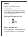
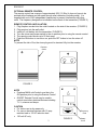
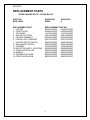
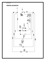
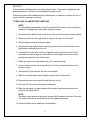
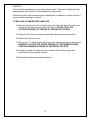
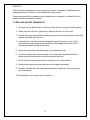
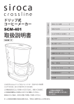
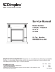
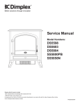
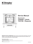
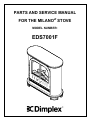
PARTS AND SERVICE MANUAL
FOR THE MILANOef STOVE
MODEL NUMBER:
EDS7001F
TABLE OF CONTENTS
OPERATION
PAGE 1
PARTS DRAWING
PAGE 3
PARTS LIST
PAGE 4
WIRING DIAGRAM
PAGE 5
UPPER LIGHT BULB REPLACEMENT
PAGE 6
LOWER LIGHT BULB REPLACEMENT
PAGE 7
MAIN ON/OFF SWITCH REPLACEMENT
PAGE 8
FLAME MOTOR/FLAME ROD REPLACEMENT
PAGE 9
HEATER ON/OFF SWITCH REPLACEMENT
PAGE 11
HEATER THERMOSTAT CONTROL
PAGE 12
POWER CORD REPLACEMENT
PAGE 13
HEATER ASSEMBLY REPLACEMENT
PAGE 14
EDS7001F
OPERATION
To access the controls go to the back of the stove.
A. MAIN ON/OFF SWITCH
The On/Off switch supplies power to all unit functions (heat/flame)
B. HEATER ON/OFF SWITCH
The HEATER ON/OFF SWITCH supplies power to the heater fan and the heater element.
C. HEATER THERMOSTAT CONTROL
To adjust the temperature to your individual requirements, turn the thermostat control
clockwise all the way to turn on the heater. When the room reached the desired
temperature, turn the thermostat knob counter clockwise until you hear a click. Leave in
this position to maintain the room temperature at this setting. For additional heat, turn
clockwise until you hear the click again and the heater will turn on. To turn the heater off,
switch the HEATER ON/OFF SWITCH to the OFF position.
NOTE
When the heater is switched ON, the heater fan will operate. The heater element may or
may not be on, depending on the thermostat control setting (SEE “HEATER
THERMOSTAT CONTROL”).
RESETTING THE TEMPERATURE CUTOFF SWITCH
This unit is equipped with a thermostat that controls the temperature of the room. It
does this by turning the heater on and off. The heater is protected with a safety device
to prevent overheating. Should the heater overheat, an automatic cut out will turn the
heater off and it will not come back on without being reset. To reset the temperature
cutoff switch turn the main power switch to the OFF position and wait five minutes
before switching the unit back on.
1
EDS7001F
OPTIONAL REMOTE CONTROL
The remote control has a range of approximately 50ft. (15.25m) it does not have to be
pointed at the fireplace and can pass through most obstacles (including walls). It is
supplied with one of 243 independent frequencies to prevent interference with other
units. The frequency designation is indicated on the back of the transmitter (FIGURE 3)
REMOTE CONTROL INSTALLATION
1. Plug fireplace cordset into the outlet located on the side of the receiver. (FIGURE 2)
2. Plug receiver into the wall outlet.
3. Install a 9 volt battery into the transmitter. (FIGURE 3)
4. Turn the stove main power switch to the on position prior to using the remote control.
5. The remote control works up to 50 feet away.
6. Push the ON button to turn stove on, push the OFF button to turn the stove off.
NOTE
To prevent the risk of fire, the stove plug must be inserted fully into the receiver.
Receiver
Outlet
FIGURE 2
NOTE
• Fireplace MAIN on/off switch must be in the
ON position prior to using the Remote Control.
• ON/OFF Remote Control may be used to
control most other electrical devices including
T.V.’s, stereos and lamps.
CAUTION
• For indoor use in dry areas only
• For use on electrical devices with 15 amp
resistive load or 1/3 HP inductive load
• 120 volt AC only
2
OPEN
Frequency
Code
FIGURE 3
Battery
Cover
EDS7001F
12
13
3
6
13
8
7
1
11
9
10
6
4
14
2
5
3
EDS7001F
REPLACEMENT PARTS
STOVE- MILANO STYLE - GLOSS BLACK
PART NO.
MOD LEVEL
6900830100
NONE
REPLACEMENT PART
1. LOG SET
2. FRONT DOOR
3. TOP PANEL
4. MOTOR, ELECTRIC
5. HEATER ASSEMBLY
6. LOWER LIGHT HARNESS
7. HEATER ON/OFF SWITCH
8. MAIN ON/OFF SWITCH
9. CORDSET
10. REFLECTOR ASS’Y, ROTATING
11. FRONT DOOR GLASS
12. MIRROR
13. THERMOSTAT KNOB
14. FRONT DOOR KNOB
REPLACEMENT PART NO.
0438270100RP
0438270100RP
0438390100RP
0438390100RP
1103740104RP
1103740104RP
2000140300RP
2000140300RP
6902420100RP
6902420100RP
2500170100RP
2500170100RP
2800070200RP
2800070200RP
2800070200RP
2800070200RP
4100040300RP
4100040300RP
5900080600RP
5900080600RP
5900200100RP
5900200100RP
5900210100RP
5900210100RP
8800000300RP
8800000300RP
8800320100RP
8800320100RP
4
6900830100
A
EDS7001F
WIRING DIAGRAM
5
EDS7001F
If unit was operating prior to servicing allow at least 10 minutes for light bulbs and
heating element to cool off to avoid accidental burning of skin.
Disconnect power before attempting any maintenance or cleaning to reduce the risk of
electric shock or damage to persons.
Light bulbs need to be replaced when you notice a dark section of the flame or when the
clarity and detail of the log exterior disappears. There is one bulb at the top of the
opening that illuminates the log set exterior and two bulbs under the log set which
generate the flames and embers.
It is a good idea to replace all of the light bulbs at one time if they are close to the end of
their rated life. Group replacement will reduce the number of times you need to open
the unit to replace the light bulbs.
TO REPLACE THE UPPER LIGHT BULB
1. Unscrew the two black knobs on the front of the unit by turning counterclockwise.
2. Grasp onto the front door, gently lift up and pull the door off of the unit.
3. Unscrew the bulb counter clockwise.
4. Insert new bulb.
5. Install the front door over the rods, gently lifting up to engage the door into the slot
in the roof.
6. Screw the two black knobs clockwise until tightened.
UPPER LIGHT BULB REQUIREMENTS
Quantity of 1 clear chandelier or candelabra bulbs with an E-12 (small) socket base, 7
watt rating.
6
EDS7001F
If unit was operating prior to servicing allow at least 10 minutes for light bulbs and
heating element to cool off to avoid accidental burning of skin.
Disconnect power before attempting any maintenance or cleaning to reduce the risk of
electric shock or damage to persons.
Light bulbs need to be replaced when you notice a dark section of the flame or when the
clarity and detail of the log exterior disappears. There is one bulb at the top of the
opening that illuminates the log set exterior and two bulbs under the log set which
generate the flames and embers.
It is a good idea to replace all of the light bulbs at one time if they are close to the end of
their rated life. Group replacement will reduce the number of times you need to open
the unit to replace the light bulbs.
TO REPLACE THE LOWER LIGHT BULBS
1. Unscrew the two black knobs on the front of the unit by turning counterclockwise.
2. Grasp onto the front door, gently lift up and pull the door off of the unit.
3. Remove the screw from the logset located in the center of the emberbed and
remove the logset from the unit.
4. Locate and examine the bulbs to determine which bulb(s) required replacement.
5. Unscrew the bulb(s) counter clockwise.
6. Insert new bulb(s).
7. Install the logset into the unit, pushing firmly against the glass. Replace the logset
retaining screw into the ember bed.
8. Install the front door over the threaded rods, gently lifting up to engage the door
into the slot in the roof.
9. Screw the two black knobs clockwise until tightened.
LOWER LIGHT BULB REQUIREMENTS
Quantity of 2 clear chandelier or candelabra bulbs with an E-12 (small) socket base, 60
watt rating. Example GE 60BC of Philips 60 CTC.
7
EDS7001F
If unit was operating prior to servicing allow at least 10 minutes for light bulbs and
heating element to cool off to avoid accidental burning of skin.
Disconnect power before attempting any maintenance or cleaning to reduce the risk of
electric shock or damage to persons.
TO REPLACE MAIN ON/OFF SWITCH
1. Unscrew the two black knobs on the front of the unit by turning counterclockwise.
2. Grasp onto the front door, gently lift up and pull the door off of the unit.
3. Remove the upper light bracket mounting screws from the top and remove the light
bracket assembly from the unit.
4. Locate the four cam locks on the side panels inside the upper corners of the
stove and turn with a large slot screwdriver so the triangle on the cam lock is
pointing up towards the top of the stove.
5. Grasp the top at both sides and gently pull to release the top.
6. Locate the main on/off switch mounted on the rear panel and disconnect the
wiring clips and connections noting their original locations.
7. Depress the retainer clips on the rear of the switch and push the switch out of the
rear cover.
8. Properly orientate the new switch and connect all of the wiring clips and
connections.
9. Reassemble in the reverse order as above.
8
EDS7001F
If the unit was operating prior to servicing allow at least 10 minutes for light bulbs and
heating element to cool off to avoid accidental burning of skin.
Disconnect power before attempting any maintenance or cleaning to reduce the risk of
electric shock or damage to persons.
TO REPLACE FLAME MOTOR/FLAME ROD
NOTE
Do to the partial disassembly of the stove care must be taken not to scratch any
surfaces or damage any components during the repair.
1. Unscrew the two black knobs on the front of the unit by turning counterclockwise.
2. Grasp onto the front door, gently lift up and pull the door off of the unit.
3. Remove logset screw and remove logset.
4. Remove the upper light bracket mounting screws from the top and remove the
light bracket assembly from the unit.
5. Locate the four cam locks on the side panels inside the upper corners of the
stove and turn with a large slot screwdriver so the triangle on the cam lock is
pointing up towards the top of the stove.
6. Grasp the top at both sides and gently pull to release the top.
7. Locate and remove the mirror by pulling it out of the slots being careful not to
bump or drop it.
8. Remove the (2) screws from the front mirror panel.
9. Slide the rounded side panels straight up and remove both panels.
10. Remove the front mirror panel through the front of unit.
11. Remove (10) screws from back panel assembly.
12. Slide the rear panel up approximately four inches, locate and disconnect the
wiring for the flame motor.
NOTE
The flame motor wires are secured in a strain relief located in the rear of the unit.
The strain relief can be loosened with a flat headed screwdriver.
13. Locate the flame motor and flame rod assembly.
9
EDS7001F
If the unit was operating prior to servicing allow at least 10 minutes for light bulbs and
heating element to cool off to avoid accidental burning of skin.
Disconnect power before attempting any maintenance or cleaning to reduce the risk of
electric shock or damage to persons.
TO REPLACE FLAME MOTOR/FLAME ROD
14. Remove the flame rod from the flame motor by pulling the end of the rod to the
left and cut the reflector spring with wire cutters. DO NOT TAKE THE
LEFTOVER SPRING OFF THE END OF THE REFLECTOR ROD
15. Remove the (2) motor mounting screws with a short handled screw driver.
16. Discard the old flicker motor.
17. Pick up the 1 ½” rubber sleeve and locate over remaining spring on reflector rod.
ENSURE TO LOCATE THE LARGE OPENING OF THE RUBBER SLEEVE
OVER THE REMAINING SPRING OF THE REFLECTOR ROD.
18. Properly orientate the flame motor and connect all of the wiring clips and
connections in their original locations.
19. Reassemble in the reverse order as above.
10
EDS7001F
If the unit was operating prior to servicing allow at least 10 minutes for light bulbs and
heating element to cool off to avoid accidental burning of skin.
Disconnect power before attempting any maintenance or cleaning to reduce the risk of
electric shock or damage to persons.
TO REPLACE HEATER ON/OFF SWITCH
1. Unscrew the two black knobs on the front of the unit by turning counterclockwise.
2. Grasp onto the front door, gently lift up and pull the door off of the unit.
3. Remove the upper light bracket mounting screws from the top and remove the light
bracket assembly from the unit.
4. Locate the four cam locks on the side panels inside the upper corners of the
stove and turn with a large slot screwdriver so the triangle on the cam lock is
pointing up towards the top of the stove.
5. Grasp the top at both sides and gently pull to release the top.
6. Locate the heater on/off switch mounted on the rear panel and disconnect the
wiring clips and connections noting their original locations.
7. Depress the retainer clips on the rear of the switch and push the switch out of the
rear cover.
8. Properly orientate the new switch and connect all of the wiring clips and
connections.
9. Reassemble in the reverse order as above.
11
EDS7001F
If the unit was operating prior to servicing allow at least 10 minutes for light bulbs and
heating element to cool off to avoid accidental burning of skin.
Disconnect power before attempting any maintenance or cleaning to reduce the risk of
electric shock or damage to persons.
TO REPLACE HEATER THERMOSTAT
1. Unscrew the two black knobs on the front of the unit by turning counterclockwise.
2. Grasp onto the front door, gently lift up and pull the door off of the unit.
3. Remove the upper light bracket mounting screws from the top and remove the light
bracket assembly from the unit.
4. Locate the four cam locks on the side panels inside the upper corners of the
stove and turn with a large slot screwdriver so the triangle on the cam lock is
pointing up towards the top of the stove.
5. Grasp the top at both sides and gently pull to release the top.
6. Locate the heater thermostat mounted on the rear panel and disconnect the
wiring clips and connections noting their original locations.
7. Pull off the thermostat control knob to expose the mounting screws.
8. Remove the mounting screws and remove the heater thermostat.
9. Properly orientate the new heater thermostat and connect all of the wiring clips
and connections.
10. Reassemble in the reverse order as above.
12
EDS7001F
If the unit was operating prior to servicing allow at least 10 minutes for light bulbs and
heating element to cool off to avoid accidental burning of skin.
Disconnect power before attempting any maintenance or cleaning to reduce the risk of
electric shock or damage to persons.
TO REPLACE POWER CORD
1. Unscrew the two black knobs on the front of the unit by turning counterclockwise.
2. Grasp onto the front door, gently lift up and pull the door off of the unit.
3. Remove the upper light bracket mounting screws from the top and remove the light
bracket assembly from the unit.
4. Locate the four cam locks on the side panels inside the upper corners of the
stove and turn with a large slot screwdriver so the triangle on the cam lock is
pointing up towards the top of the stove.
5. Grasp the top at both sides and gently pull to release the top.
6. Locate the main on/off switch mounted on the rear panel and disconnect the
wiring connections noting their original locations.
7. Remove (10) screws from back panel assembly.
8. Slide the rear panel up approximately four inches.
9. Locate and remove the wiring connections for the power cord.
10. With needle nose pliers grasp the power cord strain relief grommet from inside
the rear cover and push while twisting to remove.
11. Pull the old power cord out through the rear cover.
12. Install the power cord retaining grommet on the power cord and insert into the
hole in the rear cover.
13. Reconnect all of the wiring clips and connections.
NOTE
The wires that require to be wire connected together are secured in a strain
relief. The strain relief can be loosened with a flat headed screwdriver.
14. Reassemble in the reverse order as above.
13
EDS7001F
If the unit was operating prior to servicing allow at least 10 minutes for light bulbs and
heating element to cool off to avoid accidental burning of skin.
Disconnect power before attempting any maintenance or cleaning to reduce the risk of
electric shock or damage to persons.
TO REPLACE THE HEATER ASSEMBLY
NOTE
Do to the partial disassembly of the stove care must be taken not to scratch any
surfaces or damage any components during the repair.
1. Unscrew the two black knobs on the front of the unit by turning counterclockwise.
2. Grasp onto the front door, gently lift up and pull the door off of the unit.
3. Remove logset screw and remove logset.
4. Remove the upper light bracket mounting screws from the top and remove the
light bracket assembly from the unit.
5. Locate the four cam locks on the side panels inside the upper corners of the
stove and turn with a large slot screwdriver so the triangle on the cam lock is
pointing up towards the top of the stove.
6. Grasp the top at both sides and gently pull to release the top.
7. Locate and remove the mirror by pulling it out of the slots being careful not to
bump or drop it.
8. Remove (10) screws from back panel assembly.
9. Locate the main on/off switch mounted on the rear panel and disconnect the
wiring connections noting their original locations.
10. Remove the (2) screws from the front mirror panel.
11. Slide the rounded side panels straight up and remove both panels.
12. Remove the front mirror panel through the front of unit.
13. Remove (2) rear nylon clips from bottom panel.
14. Loosen strain relief with flat headed screwdriver located on bottom of unit.
15. Locate and remove the two screws in front of the light bulbs from the main
component panel.
14
EDS7001F
If the unit was operating prior to servicing allow at least 10 minutes for light bulbs and
heating element to cool off to avoid accidental burning of skin.
Disconnect power before attempting any maintenance or cleaning to reduce the risk of
electric shock or damage to persons.
TO REPLACE THE HEATER ASSEMBLY
16. Remove the flame rod/flame motor assembly thru the rear of the unit.
17. Remove the front grill.
18. Remove the front panel screws from both side panels using a short handled
screwdriver.
19. Locate and remove all of the heater assembly retaining screws from the blower
mounting panel.
20. Disconnect the wiring clips and connections noting their original locations and
remove the heater assembly.
21. Properly orientate the heater assembly and connect all of the wiring clips and
connections in their original locations.
22. Reassemble in the reverse order as above.
15