1
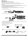
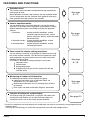
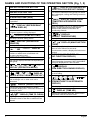
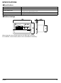
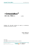
OPERATION MANUAL
CENTRAL REMOTE CONTROLLER
MODELS
DCS302CA61
Read these instructions carefully before installation.
Keep this manual in a handy place for future reference.
This manual should be left with the equipment owner.
BEFORE USE
䡲 GENERAL DESCRIPTION OF SYSTEM
This central remote controller can monitor and control up to 64 indoor unit groups.
Using two central remote controllers allows monitoring and controlling of up to 128 indoor unit groups.
Main Functions
1. Batch starting and stopping of indoor units connected to the central remote controller.
2. Handling of operation settings such as start/stop, timer operation, remote controller prohibition/permission, etc.,
and operation status settings such as temperature.
3. Operation status monitoring of operation mode, set temperature, etc.
4. Can be connected to an external central monitor panel and key system using the forced stop input
(non-voltage a connector).
• When using 1 central remote controller
• When using 2 central remote controllers
(The central remote controller and the separately sold remote control adapter circuit board or group remote control adapter cannot be used together.)
∗ GROUP OF INDOOR UNIT refers to the below.
1. A single indoor unit without remote controller
A single indoor unit without
remote controller
A single indoor unit controlled by
one or two remote controllers
Indoor unit
Remote
controller
Two remote
controllers
Remote controller not used
Maximum of 16 indoor units, group-controlled by one or two remote controllers
A maximum of 16 units
Remote
controller
1
A maximum of 16 units
Two remote
controllers
English
∗ Zone control from the central remote controller
Zone control is available from the central remote controller. With it, it is possible to make unified settings for multiple groups, so setting operations are greatly simplified.
• Any setting you make within a given zone will apply to all groups in the said zone.
• A maximum of 64 zones can be set from a single central remote controller.
(Each zone contains a maximum of 64 groups.)
• Zones can be set randomly from the central remote controller.
SAFETY CONSIDERATIONS
Please read these “SAFETY CONSIDERATIONS”
carefully before installing air conditioning equipment
and be sure to install it correctly.
After completing the installation, make sure that the
unit operates properly during the start-up operation.
Please instruct the customer on how to operate the unit
and keep it maintained.
Also, inform customers that they should store this installation
manual along with the operation manual for future reference.
This air conditioner comes under the term “appliances
not accessible to the general public”.
Meaning of warning, caution and note symbols.
WARNING ....Indicates a potentially hazardous situation which, if not avoided, could
result in death or serious injury.
CAUTION .... Indicates a potentially hazardous
situation which, if not avoided, may
result in minor or moderate injury. It
may also be used to alert against
unsafe practices.
NOTE........... Indicates situation that may result
in equipment or property-damageonly accidents.
Keep these warning sheets handy so that you can
refer to them if needed.
Also, if this equipment is transferred to a new user, make
sure to hand over this operation manual to the new user.
WARNING
In order to avoid electric shock, fire or injury, or if
you detect any abnormality such as smell of fire, turn
off power and call your dealer for instructions.
Ask your dealer for installation of the air conditioner.
Incomplete installation performed by yourself may
result in a water leakage, electric shock, and fire.
English
Ask your dealer for improvement, repair, and maintenance.
Incomplete improvement, repair, and maintenance may
result in a water leakage, electric shock, and fire.
Improper installation or attachment of equipment or
accessories could result in electric shock, short-circuit,
leaks, fire or other damage to the equipment. Be sure only
to use accessories made by Daikin which are specifically
designed for use with the equipment and have them
installed by a professional.
Ask your dealer to move and reinstall the air conditioner or the remote controller.
Incomplete installation may result in a water leakage,
electric shock, and fire.
Never let the indoor unit or the remote controller get wet.
It may cause an electric shock or a fire.
Never use flammable spray such as hair spray,
lacquer or paint near the unit.
It may cause a fire.
Never replace a fuse with that of wrong ampere
ratings or other wires when a fuse blows out.
Use of wire or copper wire may cause the unit to
break down or cause a fire.
Never inspect or service the unit by yourself.
Ask a qualified service person to perform this work.
Cut off all electric waves before maintenance.
Do not wash the air conditioner or the remote
controller with excessive water.
Electric shock or fire may result.
Do not install the air conditioner or the remote controller
at any place where flammable gas may leak out.
If the gas leaks out and stays around the air conditioner, a fire may break out.
Do not touch the switch with wet fingers.
Touching a switch with wet fingers can cause electric shock.
CISPR 22 Class A Warning:
This is a class A product. In a domestic environment this product may cause radio interference in which case the user may
be required to take adequate measures.
2
Fig. 1
Fig. 2
Fig. 3
3
Fig. 4
English
Fig. 5
Fig. 6
Fig. 7
Fig. 8
4
English
CAUTION
After a long use, check the unit stand and fitting
for damage.
If they are left in a damaged condition, the unit may
fall and result in injury.
Do not allow a child to mount on the unit or avoid
placing any object on it.
Falling or tumbling may result in injury.
Do not let children play on and around the unit.
If they touch the unit carelessly, it may result in injury.
Do not place a flower vase and anything containing water.
Water may enter the unit, causing an electric shock or fire.
Never touch the internal parts of the controller.
Do not remove the front panel. Some parts inside are dangerous to touch, and a machine trouble may happen.
For checking and adjusting the internal parts, contact
your dealer.
Avoid placing the controller in a spot splashed
with water.
Water coming inside the machine may cause an electric
leak or may damage the internal electronic parts.
Do not operate the air conditioner when using a
room fumigation - type insecticide.
Failure to observe could cause the chemicals to become
deposited in the unit, which could endanger the health of
those who are hypersensitive to chemicals.
Safely dispose of the packing materials.
Packing materials, such as nails and other metal or
wooden parts, may cause stabs or other injuries.
Tear apart and throw away plastic packaging bags so
that children will not play with them. If children play
with a plastic bag which was not torn apart, they face
the risk of suffocation.
Do not turn off the power immediately after stopping operation.
Always wait at least five minutes before turning off the
power. Otherwise, water leakage and trouble may occur.
The appliance is not intended for use by young
children or infirm persons without supervision.
The remote controller should be installed in
such a way that children cannot play with it.
NOTE
Never press the button of the remote controller
with a hard, pointed object.
The remote controller may be damaged.
Never pull or twist the electric wire of the remote
controller.
It may cause the unit to malfunction.
Do not place the controller exposed to direct sunlight.
The LCD display may get discolored, failing to display the data.
Do not wipe the controller operation panel with
benzine, thinner, chemical dustcloth, etc.
The panel may get discolored or the coating peeled
off. If it is heavily dirty, soak a cloth in water-diluted
neutral detergent, squeeze it well and wipe the panel
clean. And wipe it with another dry cloth.
Dismantling of the unit, treatment of the refrigerant, oil and eventual other parts, should be done
in accordance with the relevant local and
national regulations.
CONTENTS
BEFORE USE ..................................................... 1
OPERATION MODE ........................................ 13
GENERAL DESCRIPTION OF SYSTEM .............. 1
SAFETY CONSIDERATIONS ....................... 2
FEATURES AND FUNCTIONS .................... 6
Setting operation mode .........................................16
Group monitoring ..................................................16
Error diagnosing function .....................................17
Setting master remote controller ..........................20
Display of time to clean .........................................21
INSTALLATION TABLE ................................ 22
OPTIONAL ACCESSORIES ......................... 23
NAMES AND FUNCTIONS OF THE
OPERATING SECTION .................................. 7
OPERATION........................................................ 8
Individual screen, all screen, zone screen ............. 8
Batch operation and stop method ......................... 9
Group operation and stop method.......................... 9
Registering zones................................................... 9
Zone operation and stop method ......................... 10
Changing the fan direction and fan strength ........ 11
Changing the ventilation mode and
ventilation strength .............................................. 11
Timer Number Setting ......................................... 11
Setting the Operation Code.................................. 12
5
DOUBLE CENTRAL REMOTE
CONTROLLERS ............................................... 23
SPECIFICATIONS ............................................ 24
Specifications .......................................................24
Outline drawings ..................................................24
Fig. 1, 2, 3, 4...............................................................3
Fig. 5, 6, 7, 8...............................................................4
Fig. 9, 10, 11, 12.......................................................25
Fig. 13, 14, 15, 16.....................................................26
English
FEATURES AND FUNCTIONS
Operation menu
This central remote controller can operate and stop machines by
either group or zone.
Batch operation and batch stop functions are also available. When
used in combination with the schedule timer (optional accessory),
timer operation and stop functions are available.
See page
8—12.
Various operation modes.
You can operate the system from both this unit and the remote
controller, so to enable various operation control patterns. Twenty
different operation modes are available including five operation
patterns:
1. Start/stop:
remote controller prohibition, remote
controller stop-only permission, central
priority, after-press priority, remote controller
permission timer
2. Operation modes: remote controller prohibition, remote
controller permission
3. Set temperature: remote controller prohibition, remote
controller permission
See page
13—15.
Zone control for simpler setting procedures
You can control a maximum of 64 groups of indoor units by using
this central remote controller. You don’t have to repeat the same
setting operations by group because you can make each of the
following settings by zone.
A functions is available for setting all groups in one batch.
Operation mode
Control mode
Setting temperature
Programming time No. (Used in conjunction with the
schedule timer)
See page
8—16.
Monitoring all indoor unit information
The following information can be displayed by group.
Operation information such as operation mode, set
temperature, etc., for indoor units
Maintenance information such as cleaning signs for filters
or elements
Error codes and other malfunction diagnosis information
See page
16—21.
Function of refrigerant system display
This display helps you understand, at a glance, the indoor units
sharing the same outdoor unit and the particular indoor unit
among them that is set as the master remote controller.
See page 20.
• Room air conditioners and multi-purpose air conditioners may also be connected by using separately-sold
adapter boards.
This may limit functionality, so consult the manuals that come with each adapter board.
English
6
NAMES AND FUNCTIONS OF THE OPERATING SECTION (Fig. 1, 2)
1
2
UNIFIED OPERATION BUTTON
“
” DISPLAY (COOLING/HEATING
SELECTION PRIVILEGE NOT SHOWN)
Press to operate all indoor units.
13 For zones or individual units (groups) for which
UNIFIED STOP BUTTON
this is displayed, cooling and heating cannot be
selected.
Press to stop all indoor units.
OPERATION LAMP (RED)
3 Lit white any of the indoor units under control is
in operation.
“
” DISPLAY (REFRIGERANT
4 SYSTEM DISPLAY)
“
” DISPLAY (UNDER HOST
COMPUTER INTEGRATED CON14 TROL)
While this display is lit up, no settings can be
made. It lights up when the upper central
machines are present on the same air
conditioning network.
This indication in the square is lit while the
refrigerant system is being displayed.
5 “
“
” DISPLAY
15 (PRESET TEMPERATURE)
” DISPLAY (ZONE SETTING)
The lamp is lit while setting zones.
Displays the preset temperature.
“
” DISPLAY (OPERATION
6 MONITOR)
“
CODE)
The lamp is lit while operation is being monitored.
“
”“
16 This displays (flashes) the content of errors
” “ INDIVIDUALLY ” DISPLAY
when an error failure has occurred.
In maintenance mode, it displays the latest error
content.
7 The status displays indicates either batch
functions or which zone or individual unit
(or group) are being used.
OPERATION MONITOR
8 Each square displays the state corresponding to
“NOT AVAILABLE” DISPLAY
(NO FUNCTION DISPLAY)
17 If a function is not available in the indoor unit
even if the button is pressed, “NOT AVAILABLE”
is may be displayed for a few seconds.
each group.
“ ”“ ”“ ”“ ”“ ”“ ”“
9 DISPLAY (OPERATION MODE)
”
Displays operating state.
“
” DISPLAY
18 (FAN DIRECTION SWING DISPLAY)
This displays whether the fan direction is fixed
or set to swing.
“
”“
”“
”“
” DISPLAY
(VENTILATION CLEANING DISPLAY)
10 This is displayed when a Ventiair total enthalpy
heat exchanger unit or other such unit is
connected.
“
” DISPLAY (INSPECTION/TEST)
“ ”“ ”“ ”“ ”“ ”“
”
DISPLAY (VENTILATION
19 STRENGTH/SET FAN STRENGTH
DISPLAY)
This displays the set fan strength.
11 Pressing the maintenance/test run button
(for service) displays this. This button should not
normally be used.
“
” DISPLAY (MALFUNCTION
” DISPLAY (TIME TO CLEAN)
20
“
” DISPLAY (TIME NO.)
Displays the operation timer No. when used in
conjunction with the schedule timer.
12 It lights up when any individual unit (group) has
reached the time for the filter or element to be
cleaned.
7
English
“
” DISPLAY (OPERATION
CODE AND UNIT NUMBER DISPLAY)
21 The method of operation (remote controller
prohibited, central operation priority after-press
operation priority, etc.) is displayed by the
corresponding code.
This displays the numbers of any indoor units
which have stopped due to an error.
“
”“
” DISPLAY (TIME TO
CLEAN AIR CLEANER ELEMENT/
22 TIME TO CLEAN AIR FILTER)
Displayed to notify the user it is time to clean the
air filter or air cleaner element of the group
displayed.
VENTILATION MODE BUTTON
23 This is pressed to switch the ventilation mode of
the total enthalpy heat exchanger.
33
34
indoor unit or a zone.
ON/OFF BUTTON
26 Starts and stops ALL, ZONE, and INDIVIDUAL
units.
TEMPERATURE ADJUSTMENT
BUTTON (ZONE NUMBER BUTTON)
27 This button is pressed when setting the
temperature. Select the zone number if any
zones have been registered.
28
29
FAN DIRECTION ADJUSTMENT
BUTTON
This button is pressed when setting the fan
direction to “fixed” or “swing”.
OPERATION MODE SELECTOR
BUTTON
This sets the operation mode. The dry setting
cannot be done.
TIME NO. BUTTON
30 Selects time No. (Use in conjunction with the
schedule timer only).
31
CONTROL MODE BUTTON
Selects control mode.
FILTER SIGN RESET BUTTON
32 This button is pressed to erase the “clean filter”
display after cleaning or replacement.
English
Pressing this button scrolls through “weak”,
“strong”, and “fast”.
35 Zone registration mode can be turned on and off
by pressing the start and stop buttons simultaneously for at least four seconds.
INSPECTION/TEST RUN BUTTON
(FOR SERVICE)
36 Pressing this button scrolls through “inspection”,
“test run”, and “system display”.
This button is not normally used.
VENTILATION STRENGTH
ADJUSTMENT BUTTON
37 This button is pressed to switch the ventilation
strength (“fresh up”) of the total enthalpy heat
exchanger.
24 Pressing this button scrolls through the “all
ARROW KEY BUTTON
25 This button is pressed when calling an individual
Sets control mode and time No.
FAN STRENGTH ADJUSTMENT
BUTTON
ZONE SETTING BUTTON
ALL/INDIVIDUAL BUTTON
screen”, “zone screen”, and “individual screen”.
SET BUTTON
(Notes)
1. Please note that all the displays in the figure
appear for explanation purposes or when the
cover is open.
2. If the unit is used in conjunction with other optional
central controllers, the OPERATION LAMP of the
unit that is not under operation control may light
up and go out a few minutes behind schedule.
This shows that the signal is being exchanged,
and does not indicate any failure.
OPERATION
䡲 Individual screen, all screen,
zone screen (Fig. 3)
This controller can perform operations in the individual
screen, all screen, or zone screen.
• Individual screen The individual screen is used
when performing group operations.
• All screen
The all screen is used when performing operations for all units at
once.
• Zone screen
The zone screen is used when
performing zone operations.
1.
Select the screen by pressing the
“ALL/INDIVIDUAL” button.
Every time the “ALL/INDIVIDUAL” button is
pressed, the selection scrolls through INDIVIDUAL
→ ALL → ZONE.
If nothing is done in the all or zone screens for one
minute, it automatically goes to the individual
screen.
8
• If the zone number in the zone screen is displayed as “---,” this indicates that no units are
registered in a zone.
Please perform zone registration before proceeding in the zone screen. (See page 9)
䡲 Batch operation and stop method
(Fig. 4)
䡲 Group operation and stop method
(Fig. 5)
This is for operating or stopping connected units in
groups.
[Group operation]
1. Press the
to enter the
This is for operating or stopping all connected units at
once.
A. What to do when operating or stopping all
connected units at once.
1. Press either
“
“
2.
”.
The “
3.
2.
The “
Press the “TEMPERATURE ADJUSTMENT” button.
The temperature rises 1° every time
the ( ) button is pressed.
The temperature drops 1° every time
the ( ) button is pressed.
Set to “
” when you do not wish to use batch
setting for the temperature setting.
Setting to 1° above or below the temperature
setting range displays “
4.
”.
Call up the desired mode by pressing
the “OPERATION MODE SELECTOR” button.
” display lights up in the group.
” display goes off in the group.
Press the “TEMPERATURE ADJUSTMENT” button.
The temperature rises 1° every time the
( ) button is pressed.
The temperature drops 1° every time the
( ) button is pressed.
Temperature adjustment cannot be done if the
selected group’s air conditioners are in fan mode.
” display lights up on all connected units.
The “
” display goes off on all connected units.
Operation and stop in the batch screen are done
the same as with the batch operation and batch
stop buttons.
3.
4.
” display lights up on all registered units.
Press the “RESET” button.
” in this screen has selected unit 1-04.
Press the “RESET” button.
Press the “SELECT” button.
The “
move the
Press the “SELECT” button.
The “
Press the “ALL/INDIVIDUAL button” to
enter the all screen.
The “
Using the arrow keys,
“
” to select the units to operate or stop.
Keeping the button pressed down will move it
rapidly.
B. Batch Operation
1.
individual screen.
The unit will enter the individual screen automatically if nothing is done for one minute.
” or
• Operation can be performed from the individual screen, the all screen, or the zone
screen.
• The “TEMPERATURE ADJUSTMENT” and
“OPERATION MODE SELECTOR” buttons
cannot be used.
To set the temperature and operation mode,
use B. batch operation.
“ALL/INDIVIDUAL button”
5.
Call up the desired mode by pressing
the “OPERATION MODE SELECTOR” button.
䡲 Registering zones (Fig. 6)
It is possible to set multiple groups as one zone and
control each zone separately.
No zones are registered when the unit is shipped from
the factory.
Zone registration can be done in the individual screen,
all screen, or zone screen.
[Registration]
1.
Pressing the “ALL/INDIVIDUAL”
button for four seconds.
Displays
ZONE SET.
Zone Number 1 will be displayed, and if there are
any groups already registeredd displayed zone, a
“
” will light up on the operation monitor.
Set to “
” when you do not wish to use batch setting for the operation setting.
9
English
2.
Select the Zone Number to be registered using the “ZONE NUMBER” button.
[Batch deletion of zone registration]
1.
Keeping the button pressed down will move it
rapidly.
3.
“
” to the group you wish to
ister using the arrow keys.
reg-
Keeping the button pressed down will move it
rapidly.
4.
Press the “SELECT” button to register
that group to the zone.
The “
units.
” display lights up on all the selected
Pressing the “RESET” button
removes the group from that zone, and
“
” goes off.
Pressing the “
” for at least
four seconds while
pressing the “FILTER SIGN RESET” button when
“ZONE SET” is displayed will delete all
zone registrations.
The zone registrations for all units will be lost.
䡲 Zone operation and stop method
(Fig. 7)
This is for operating or stopping connected units in
zones.
[Zone operation]
1.
Press the “ALL/INDIVIDUAL button” to
enter the zone screen.
2.
Using the arrow keys, select the zone
number to operate or stop.
Repeat steps 3 and 4 until all the units you wish to
register to the zone have been added.
Pressing
and
reduces the zone number
while
and
raise the number.
Keeping the button pressed down will move it
rapidly.
• If the zone number is displayed as “---,” this
indicates that no units are registered in a
zone. Please perform zone registration
before using a zone. (See page 9)
3.
In this example, a screen is shown with
units 1-00, 1-02, 1-03, and 2-00 registered
to Zone Number 1.
The “
6. Once zone registration is complete,
The “
4.
press the “ALL/INDIVIDUAL” button
to turn off “ZONE SET” display and return
to the individual screen.
” display goes off in the group.
Press the “TEMPERATURE ADJUSTMENT” button.
The temperature rises 1° every time the ( ) button is pressed.
The temperature drops 1° every time the ( ) button is pressed.
The display returns to the normal screen if nothing
is done for one minute when in zone registration
mode.
(NOTE)
• It is impossible to register one group to several
different zones.
If this is done, the last zone registered to will be
valid.
” display lights up in the group.
Press the “RESET” button.
5. Repeat steps 2 to 4 to register to the next
zone.
Press the “SELECT” button.
Set to “
” when you do not wish to use zone
setting for the temperature setting.
Setting to 1° above or below the temperature
setting range displays “
5.
”.
Call up the desired mode by pressing
the “OPERATION MODE SELECTOR” button.
Set to “
” when you do not wish to use zone setting for the operation mode.
English
10
䡲 Changing the fan direction and fan
strength (Fig. 8)
3.
This changes the fan direction and strength settings in
the air conditioner.
Changing the fan direction and strength is done in the
individual screen.
It will scroll through “
→“
to enter the
2.
individual screen.
Using the arrow keys,
move the
“
” to select the units to fan direction
adjustment or fan strength adjustment.
Keeping the button pressed down will move it
rapidly.
3.
Press the “FAN DIRECTION ADJUSTMENT” button.
This sets “fixed” or “swing” for the fan direction.
Press the “FAN STRENGTH ADJUSTMENT” button.
Pressing this button scrolls through “
and “
”, “
”,
”.
Depending on the indoor unit, only “
” and “
”
The functions included in the indoor units may vary.
Pressing a button for a function which is not available
will cause “NOT AVAILABLE” to be displayed.
“
This changes the ventilation mode and strength settings in the total enthalpy heat exchanger.
Changing the ventilation mode and strength is done in
the individual screen.
[Registration]
Press the “ALL/INDIVIDUAL button” to
individual screen.
The unit will enter the individual screen automatically if nothing is done for one minute.
2.
Using the arrow keys,
”→“
”→“
”→“
”→
”.
The fresh up function may not be available
depending on the connected unit model.
The functions included in the indoor units may vary.
Pressing a button for a function which is not available
will cause “NOT AVAILABLE” to be displayed.
• Ventilation Mode and Amount
If these are changed using the remote controller
depending on the unit model, they cannot be displayed on the central remote controller.
To monitor the ventilation mode and amount, check
the values on the remote controller.
䡲 Timer Number Setting (Fig. 10)
(Only when used with the schedule timer)
Using this together with the schedule timer makes it
possible to set on and off times four times a day.
1.
move the
“
” to select the units to ventilation
mode or ventilation strength adjustment.
Pressing the “TIMER NO.” button
causes the number set for timer number 1
to blink.
If no timer setting has been made
䡲 Changing the ventilation mode and
ventilation strength (Fig. 9)
enter the
”
[Registration]
may be available.
1.
”→“
”.
It will scroll through “
Press the “ALL/INDIVIDUAL button”
The unit will enter the individual screen automatically if nothing is done for one minute.
”→“
Press the “VENTILATION STRENGTH
ADJUSTMENT” button.
[Registration]
1.
Press the “VENTILATION MODE”
button.
“ ” will be displayed.
Select the desired timer number
by pressing the
“TIMER
NO.” button.
2.
Once the desired timer number is
displayed, press the “SET” button.
Press the
“SET” button
within 10 seconds after the timer
number is displayed.
The display will return to how it
was after 10 seconds.
The display for timer number 1
will stop blinking and then timer number 2 will start
blinking.
Keeping the button pressed down will move it
rapidly.
11
English
3.
When using timer operation, make sure the
times do not overlap when setting the program of
the schedule timer.
Select the desired timer number by
pressing the “TIMER NO.” button.
Once the desired timer number is
displayed,
press the “SET”
button.
The display for timer number 2
will stop blinking.
The “
䡲 Setting the Operation Code (Fig. 11)
[Registration]
1.
” display will disappear
after 3 seconds.
Select “ ” in the timer number when you do not
wish to set a timer number.
It is possible to set only one timer number.
(The times for turning the unit(s) on and off twice a
day can be set with a single timer number.)
• Timer Number Setting
Group control: select the unit in the individual
screen and set the timer number.
Batch control: set the timer numbers for all connected units.
Zone control: set the timer numbers for all
zone-registered units.
Call up the zones which you wish
to set in the zone screen and set
the timer numbers.
• Since the timer number will be set to afterpress priority, the timer number in the last
screen set will be valid for the connected
units.
Example 1
Setting timer number 1 for unit 1-00 to “1” and
timer number 2 to “2” in the individual screen and
then setting timer number 1 to “3” and timer
number 2 to “4” in the batch screen causes the
timer numbers for all units to be set, so timer
number 1 for unit 1-00 will be “3” and timer number 2 will be “4”.
Pressing the “CONTROL MODE”
button causes the currently set operation
code to blink.
Call up the desired code number by pressing the
“CONTROL MODE” button.
Scroll through the code numbers.
2.
Once the code number is displayed,
press the “SET” button.
The display will stop blinking.
The operation code display will disappear after
3 seconds.
[The Operation Code Setting]
Group control: select the unit in the individual screen
and set the operation code.
Batch control: set the operation code for all connected units.
Zone control: set the operation code for all zone-registered units.
Call up the zones which you wish to set
in the zone screen and set the operation code.
Since the operation code will be set for after-press priority, setting the operation code in the zone and individual screens after setting the operation code in the
batch screen, will cause the operation codes set afterwards to be valid.
Example 2
To prevent leaving units on, timer number 1 is
set to “5” in the batch screen.
Setting timer number 1 in zone number 1 to “ ”
in the zone screen after that will change the
timer number for zone number 1, so the setting
to prevent leaving the units on will be lost for
zone number 1 only.
If a timer number is set incorrectly by accident,
redo the setting in the desired screen.
• What happens when the timer number on
time and off time are set to the same time
When the on time and off time are set to the
same time for the same timer number, operation
does not change.
When the on time and off time are set to the
same time for different timer numbers, the off
time is given priority.
English
12
OPERATION MODE
The following five operation control modes can be selected along with the temperature setting and operation mode
by remote controller, for a total of twenty different modes. These twenty modes are set and displayed with control
modes of 0 to 19. (For further details, see EXAMPLE OF OPERATION SCHEDULE on the next page.)
• ON/OFF control impossible by remote controller..... Use this mode when operating and stopping from the
central remote controller only. (ON/OFF control by the
remote controller is disabled.)
• Only OFF control possible by remote controller ...... Use this mode when executing the operation only by the
central remote controller, and executing only the stop by
remote controller.
• Centralized .............................................................. Use this mode when executing the operation only by the
central remote controller, and executing start/stop freely
by remote controller during the preset hours.
• Individual ................................................................. Use this mode when executing start/stop both by central
remote controller and remote controller.
• Timer operation possible by remote controller......... Use this mode when executing start/stop by remote controller during the preset hours, and not starting operation
by the central remote controller at the programmed time
of system start.
[HOW TO SELECT THE CONTROL MODE]
• Select whether to accept or to reject the operation from the remote controller regarding the operation, stop, temperature setting and operation mode setting, respectively, and determine the particular control mode from the
rightmost column of the table below.
Example
13
English
Control by remote controller
Operation
Operation
mode
Unified operation, individual operation by central
remote controller, or operation controlled by timer
Unified stop, individual
stop by central remote
controller, or timer
stop
Temperature control
Stop
Rejection
ON/OFF control
impossible by
remote controller
Rejection
(Example)
Acceptance
(Example)
Rejection
(Example)
Rejection
Rejection
(Example)
Only OFF control
possible by
remote controller
Acceptance
Rejection
Centralized
Acceptance
Acceptance
Acceptance
Rejection
Individual
Acceptance
Acceptance
Timer operation
possible by
remote controller
Acceptance
(During timer at
ON position only)
Rejection
Rejection
(During timer at OFF
position)
Acceptance
Operation
mode setting
Control
mode
Acceptance
0
Rejection
10
Acceptance
(Example)
1 (Example)
Rejection
11
Acceptance
2
Rejection
12
Acceptance
3
Rejection
13
Acceptance
4
Rejection
14
Acceptance
5
Rejection
15
Acceptance
6
Rejection
16
Acceptance
7
Rejection
17
Acceptance
8
Rejection
18
Acceptance
9
Rejection
19
Note) Do not select the timer operation possible without the remote controller. In this case, timer operation is disabled.
EXAMPLE OF OPERATION SCHEDULE
Operation schedule is possible only in conjunction with the schedule timer (optional accessory).
Liquid crystal display of schedule timer
ON/OFF control impossible by remote controller
Centralized
Programmed
to operate at
8:45
Remote
controller
Centralized
Programmed
to stop at
5:00
------
Operation
Start/stop by remote
controller cannot be made.
Individual
stop
Stop
English
Individual operation
except to the preset
hours
Stop controlled
by timer
Operation controlled
by timer
Forced and unified stop.
Power reminder stops.
---------
Stop
14
Only OFF control possible by remote controller
Programmed to
operate at 8:45
Remote
controller
Stop
---
Programmed to
stop at 5:00
Programmed to
operate at 5:20
---
Only stopping possible by
the remote controller.
Individual operation once
the unit is stopped.
Centralized
Stop
Remote
controller
Operation
controlled by
timer
Timer stops even
if you forget to
turn off the unit.
Operation
controlled
by timer
Centralized
---
Timer stops. Power reminder stops.
Stop
Operation
---
Programmed to
stop at 10:00
Only stopping possible by the remote controller.
Centralized
Operation
controlled
by timer
Centralized
Timer stops.
Programmed to
operate at 8:45
Remote
controller
Stop
---
Operation
Stop
Programmed to
stop at 7:00
---
Start/stop is possible by the remote controller
during the hours programmed for timer operation.
Individual
Operation starts
without fail at the
timer-programmed
time.
Centralized
Programmed to
operate at 9:00
Operation
Remote
controller
---
Stop
Operation
Start/stop is possible by the remote controller at any time
regardless of the hours programmed by the timer.
Stops temporarily at the
timer-programmed stop time.
Centralized
Stop
Remote
controller
---
Programmed to
stop at 5:00
---
Timer stops.
Stop
Operation
---
Programmed to
stop at 10:00
Start/stop is possible by the remote controller at any time
regardless of the hours programmed by the timer.
Timer operation possible by remote controller
Timer operation possible
by remote controller at
preset times.
8:30
Remote
controller
---
Stops for a time at
timer-programmed time.
Stop
Operation
---
Programmed to
stop at 5:00
Startn/stop is possible by the remote controller
during the hours programmed for timer operation.
----
--------
Centralized
---------
------------------------------------------
Centralized
------
Timer operation possible by remote controller
at preset times.
Programmed to
operate at 5:20
Remote
controller
---
Timer stops. Power
reminder stops.
Operation
Stop
---
Programmed to
stop at 10:00
Start/stop is possible by the remote controller
during the hours programmed for timer operation.
Air conditioner now operating.
- - - - - Air conditioner now stopping.
Command by central remote controller
Command by remote controller
15
English
䡲 Setting operation mode (Fig. 12)
[Registration]
1.
Press the OPERATION MODE SELECTOR BUTTON. Each time you press this
button, the display rotates as shown on
the below list.
• List of operations which can be set
In the below list, “ 䡬 ” refers to the acceptable setting, while “ × ” refers to the not acceptable setting.
∗1: Setting may not be acceptable depending on the
type of indoor unit with which this unit is connected.
∗2: In zone control, the units run in temperature adjustment mode (heating or cooling) for the outdoor system for the groups registered to those zones.
Heating or cooling selection is not available.
*3:
or
or
Changing the ventilation mode cannot be done in
the zone screen. Changing the ventilation mode
should be done in the individual screen.
∗4: In group control, the units run in temperature adjustment mode (heating or cooling) for the group outdoor
system. Heating or cooling selection is not available.
• The Zone consists of the following two cases.
A. Zone without display“
”
The group with master remote controller setting
exists in this zone.
Setting the master remote controller enables cool/
heat selection.
Operations other than cool/heat operations can also
be set for some operations. For further details, see
the list on the left.
∗
∗
∗
∗
B. Zone with display“
”
No group with master remote controller setting
exists in this zone.
The cool/heat selection is not available because the
master remote controller has not been set.
Some operations other than cool/heat operations
can be set. For further details, see the list in the left.
See page 20 if the display“
” is flashing.
• Fan operation can be performed for each zone using
the central remote controller even if there is no cooling/heating selection right during cooling or heating.
Also, if a Ventiair is connected in the zone, ventilation
and ventilation cleaning operation is possible. See
the included operating manuals for details.
• When the indoor unit is in heat operation, change the setting to FAN operation through the central remote controller; then, you can switch the fan speed to the extremely
low fan speed. Warm air may blow if any other indoor unit
belonging to the same system is in heat operation.
• The indoor fan stops during defrost/hot start.
• DRY cannot be set from the central remote controller.
∗
䡲 Group monitoring (Fig. 13)
∗
∗
∗
∗
English
∗
Utilize the group monitor function in each of the following cases:
1. Check the malfunction code.
(See the next page.)
2. Check the group that requires cleaning of the air
filter and air cleaner element. (See page 21.)
3. Change the setting of the master remote controller. (See page 20.)
4. Check the group(s) sharing the same outdoor
unit. Or, check the particular group(s) with the
master remote controller setting. (See page 20.)
5. Check the conditions of other individual groups.
16
When in zone screen
The zone screen will revert to the individual screen
automatically if nothing is done in it for one minute.
[Registration]
1.
Press the “ALL/INDIVIDUAL” button
to switch to the
2.
“INDIVIDUAL” screen.
Using the arrow key,
move the
“
” to select the unit to be monitored.
Keeping the button pressed down will move it
rapidly.
The “
” lights up and the status of that unit
is displayed in the LCD. The cursor in the screen
Fig. 13 has selected unit 2-06.
code is displayed. Check the contents of the display,
and contact your DAIKIN dealer because the above
signs can give you the idea on the trouble area.
The display “
” flashes under
the group No. where the indoor
unit that has stopped due to malfunction.
[Registration]
1.
Press the ARROW KEY BUTTON to
call up the group that has stopped due to
malfunction.
The unit No.
the malfunction code is
flashing because of an error failure.
䡲 Error diagnosing function
(Fig. 14)
This central remote controller is provided with a diagnosing function, for when an indoor unit stops due to
malfunction. In case of actuation of a safety device,
disconnection in transmission wiring for control or failure of some parts, the operation lamp, inspection display and unit No. start to flash; then, the malfunction
Operation
lamp
Maintenance
display
Unit No.
Malfunction
code
64
Indoor air thermistor error
65
Outdoor air thermistor error
68
HVU error (Ventiair dust-collecting unit)
6A
Dumper system error
6A
Dumper system error + Thermistor error
6F
Simple remote controller error
6H
94
17
Error content
Door switch (Ventiair dust-collecting unit), relay harness fault
(Ventiair dust-collecting/humidifier unit)
Ventiair internal transmission error
(between total enthalpy – fan unit)
A0
Indoor unit · external safety device error
A1
Indoor unit · BEV unit (Sky-Air connection unit) PC board
assembly fault
A1
Indoor unit · PC board assembly fault
A3
Indoor unit · Drain level error (33H)
A6
Indoor unit · Fan motor (51F) lock, overload
A7
Indoor unit · Fan direction adjustment motor (MA) error
A9
Indoor unit · BEV unit, electric expansion valve motor (20E) error
AF
Indoor unit · Malfunctioning drain
AH
Indoor unit · Dust-collector error
AJ
Indoor unit · Insufficient capacity setting, address setting fault
English
C4
C5
C9
CA
CJ
Indoor unit · remote controller sensor error
E0
Outdoor unit · Safety device operation
E1
Outdoor unit · PC board assembly fault
E1
Outdoor unit · PC board assembly fault
E3
Outdoor unit · High-pressure switch fault
E4
Outdoor unit · Low-pressure switch fault
E9
Outdoor unit · Electric expansion valve motor (20E) error
EC
Heat source unit · Intake water temperature inter-lock operation
(fan operation)
EF
Outdoor unit · Ice thermal storage unit error
F3
Outdoor unit · Discharge piping temperature error
H3
Outdoor unit · High-pressure switch operation
H4
Outdoor unit · Low-pressure switch operation
H9
H9
Outdoor unit · Outdoor air thermistor (Th1)
Error (faulty connection, cut wire, short circuit, fault)
Outdoor unit · Outdoor air thermistor (Th1)
Error (faulty connection, cut wire, short circuit, fault)
HC
Outdoor unit · Water temperature sensor system error
HF
Ice thermal storage unit error, ice thermal storage controller error,
error in outdoor unit during ice thermal storage operation
HJ
Outdoor unit · water system fault
J1
Outdoor unit · pressure sensor error
J3
J3
J5
English
Indoor unit · Liquid piping thermistor (Th2) Error (faulty connection, cut wire, short circuit, fault)
Indoor unit · BEV unit, gas piping thermistor (Th3) Error (faulty
connection, cut wire, short circuit, fault)
Indoor unit · Intake air thermistor (Th1) Error (faulty connection,
cut wire, short circuit, fault)
Indoor unit · Outlet air thermistor (Th4) Error (faulty connection,
cut wire, short circuit, fault)
Outdoor unit · Discharge piping thermistor (Th3)
Error (faulty connection, cut wire, short circuit, fault)
Outdoor unit · Discharge piping thermistor (Th3)
Error (faulty connection, cut wire, short circuit, fault)
Outdoor unit · Intake piping thermistor (Th4)
Error (faulty connection, cut wire, short circuit, fault)
J6
Outdoor unit · Heat exchange thermistor (Th2) error
J6
Outdoor unit · Heat exchange thermistor (Th2) error
Error (faulty connection, cut wire, short circuit, fault)
J7
Outdoor unit · Header thermistor (Th6) error
JA
Outdoor unit · Discharge piping pressure sensor error
JC
Outdoor unit · Intake piping pressure sensor error
JF
Outdoor unit · Oil temperature sensor (Th5) system error
JH
Outdoor unit · Oil temperature sensor (Th5) system error
L0
Outdoor unit · Inverter system fault
L4
Outdoor unit · Inverter cooler fault
L5
Outdoor unit · Ground circuit for compressor motor, short circuit,
or power unit short circuit
18
L6
Outdoor unit · Ground circuit for compressor motor, short circuit
L8
Outdoor unit · Compressor overload, compressor motor wire
disconnection
L9
Outdoor unit · Compressor lock
LA
Outdoor unit · Power unit error
LC
Outdoor unit · Transmission error between inverter and outdoor
control unit
or
M1
Central controller: PC board fault
or
M8
Transmission error between central controllers
or
MA
Central controller: Incorrect combination
or
MC
Central controller: Address setting fault
P0
Insufficient gas (thermal storage)
P1
Outdoor unit · Power voltage imbalance, phase loss
P4
Outdoor unit · Power unit temperature sensor error
U0
Pressure drop due to insufficient refrigerant, electric expansion
valve fault, etc.
U1
Reversed or lost phase
U2
Power voltage error, momentary electrical stoppage
U4
U5
Transmission error between indoor unit/BEV unit and outdoor/BS
unit, Transmission error between outdoor unit and BS unit
Transmission error between remote controller and indoor
control unit
U5
Remote controller board fault or remote controller setting fault
U6
Transmission error between indoor units
U7
U7
U8
U9
UA
Transmission error between outdoor units
Transmission error between outdoor unit and ice thermal
storage unit
Transmission error between outdoor units
(cooling/heating batch, low-noise operation)
Transmission error between master remote controller and slave
remote controller (slave remote controller error)
Incorrect combination of indoor unit and remote controller within
a single system (model)
Transmission error between indoor unit/BEV unit and outdoor
unit within a single system
Transmission error between BS unit and indoor unit/BEV unit and
outdoor unit within a single system
Incorrect combination of indoor, BS, and outdoor units within a
single system (model, number of units, etc.)
Incorrect combination of indoor unit and remote controller
(remote controller in question) BS unit connection position fault
UC
Central control group numbers overlap
UE
Transmission error between indoor unit and central controller
UF
Unset system, incorrect settings between BEV unit and
indoor unit
UH
System fault
error codes (in outline font) do not display “maintenance” and the system will run, but please check the content
of the display and contact your dealer.
19
English
䡲 Setting master remote controller
(Fig. 15)
You must set the master remote controller of the operation mode for one of the indoor units, if two or more
such indoor units with the remote controller are connected with the outdoor unit where the operation
modes such as cool/heat operation and FAN operation
can be set by remote controller and central remote controller.
1. Preparations
When switching operation
● In case of operation switch
Call up the zone including the group with the
setting of master remote controller.
(Zone without the display “
Press the OPERATION MODE SELECTOR
BUTTON several times, and switch to the
desired operation mode.
Each time you press it, the display is switched
When you want to fix settings
to “
• Check the particular group with the master
remote controller setting for the refrigerant
system you wish to reset. (See the below.)
NOTE
• Call up the group without the display
“
” (See page 16.)
Hold the OPERATION MODE SELECTOR
BUTTON down for about four seconds while
the above group is being called up.
The display “
” flashes on the liquid crystal display of the remote controller
for all the groups sharing the same outdoor
unit or BS unit.
When you turn on the power switch for the first
time, the display“
” flashes.
”)
”“
”“
” and “
” in sequence.
• However, the displays “
”“
” and “VENTILATION MODE” may appear in some zones,
depending on the type on indoor unit with which they
are connected.
(VENTILATION MODE)
or
or
[System Display]
1. Test run mode is necessary to display the system
display.
2. In order to turn on test run mode, select the appropriate air conditioner on the individual screen with
the cursor and then set its operation mode to either
cooling or heating. (The air conditioner does not
need to be running. It doesn’t matter if it is, though.)
3. Press the “inspection/test run” button twice to put it
into test run mode.
4. Pressing the “inspection/test run” button for four or
more seconds in test run mode will display
“REF CIRCUIT.”
the
2. Setting selection right
Pall up the desired group to set the master
remote controller, and
press the OPERATION MODE SELECTOR BUTTON. The master
remote controller is set for this group, and the
display “
” goes out. The display
“
” appears for the other groups.
Setting is finished now.
English
20
Call the unit whose system you wish to look up using
the arrow keys.
The “
” on all groups in the same system as the
displayed group will light up.
Of those, the “
” display in all groups which have
cooling/heating selection privilege will blink.
2.
Press the FILTER SIGN RESET BUTTON, and the display “
” disappears. (Including all the groups where the
air filter has been cleaned.)
NOTE
Be sure to check the display
“
” has
disappeared at this point. The appearance of the
above display is a sign that the air filter or air cleaner
element of some group still needs cleaning.
In this example, individual units 1-00, 1-03, 1-05,
1-06, 1-07, 2-02, and 2-03 are in the same system,
and 1-05 has the cooling/heating selection privilege.
To look up other systems, call up all the units you wish
to look up using the arrow keys.
Pressing the inspection/test run button one more time
gets rid of the system display and ends it.
The unit will enter the individual screen automatically if
nothing is done for one minute in the system display
screen.
This function may not be available for all connected
outdoor units, in which case “REF CIRCUIT” will blink.
It will also not be correctly displayed if DIII-NET extension ADP is used.
䡲 Display of time to clean (Fig. 16)
This central remote controller displays the time to clean
the air filter or air cleaner element for each group or any
given group by utilizing two types of signs. The display
“
” tells the time to clean the air filter or the air
cleaner element of some group.
If a cleaning sign is displayed
A filter or element in some group is ready to be
cleaned.
1.
Press the ARROW KEY BUTTON, and
search the groups displaying “
” or
“
” (The group may be plural.)
Clean or change the air filter or air cleaner
element.
For further details, see the operation manual
attached to each indoor unit. (Clean or change the
air filter or air cleaner element of all the groups displaying “
21
” or “
”.)
English
INSTALLATION TABLE
When installing the equipment, mark the zone No. of each group and installation location in the below table.
Setting group No.
(Setting is not possible unless power is activated to
both the central remote controller and indoor unit.)
Operated by simplified remote controller
1. Activate power to both the central remote controller
and indoor unit.
2. Remove the upper part of the remote controller.
Operated by remote controller
1. Activate power to both the central remote controller
and indoor unit.
3. Press the
BUTTON (field set) on the PC
board. The controller will enter the FIELD SET
MODE.
2. While in the normal mode, hold down the “
” button for a minimum of 4 seconds. The unified ON/
OFF controller will enter the FIELD SET MODE.
3. Select the MODE No. “
4. Use the “
” with the “
4. Select the MODE No. “
TON and
” button.
each group. (Group No. increases in the order of
1-00, 1-01 ... 1-15, 2-00, ... 8-15.)
” to set the selected group No.
6. Press “
” to return to the NORMAL MODE.
BUT-
BUTTON (temperature setting).
5. Use the
BUTTON (set A) and
BUTTON (set B) to select the group No. for each
group. (Group No. increases in the order of 1-00,
1-01 ... 1-15, 2-00, ... 8-15.)
” button to select the group No. for
5. Press “
” with the
6. Press
BUTTON (set/cancel) to set the
selected group No.
7. Press
BUTTON (field set) to return to the
NORMAL MODE.
Zone No.
Group No.
–00
–01
–02
–03
–04
–05
–06
–07
–08
–09
–10
–11
–12
–13
–14
–15
–00
–01
–02
–03
–04
–05
–06
–07
–08
–09
–10
–11
–12
–13
–14
–15
Indoor unit
Quantity of units
Controlled by
Location
Zone No.
Group No.
Indoor unit
Quantity of units
Controlled by
Location
English
22
Zone No.
Group No.
–00
–01
–02
–03
–04
–05
–06
–07
–08
–09
–10
–11
–12
–13
–14
–15
–00
–01
–02
–03
–04
–05
–06
–07
–08
–09
–10
–11
–12
–13
–14
–15
Indoor unit
Quantity of units
Controlled by
Location
Zone No.
Group No.
Indoor unit
Quantity of units
Controlled by
Location
OPTIONAL ACCESSORIES
You can perform the normal operation, take off the malfunction contact point and unified start/stop by contact
point, all by connecting this unit with the unification adaptor for computerized control. For further details, ask
your DAIKIN dealer.
(a) Unification adaptor for computerized control
(b) Central remote controller
DOUBLE CENTRAL REMOTE CONTROLLERS
With two central remote controllers, centralized control (indoor units) is possible from different locations.
(a) Central remote controller
(b) Group No. 1 – 00
(c) Group No. 1 – 15
( f ) A maximum of 64 groups
(e) Group No. 4 – 15
(d) Group No. 2 – 00
Note)
• For control alignment and settings for double central remote controllers, contact your dealer.
23
English
SPECIFICATIONS
䡲 Specifications
Power supply
1 ~ 50/60Hz, 100V – 240V
Power consumption
Max. 8W
Forced ON/OFF input
Continuous “a” contact
Contact current: approximately 10mA
Size
180 (W) × 120 (H) × 64.5 (D)
Weight
420g
䡲 Outline drawings
When using this unit an electric parts box of KJB311AA is required.
For installation, a steel electric parts box to be embedded is mandatory.
English
24
2
4
5
1
3
6
Fig. 9
Fig. 10
Fig. 11
Fig. 12
English
25
Fig. 13
Fig. 14
Fig. 15
Fig. 16
English
26
3P124623-8D EM05A046
(0510) HT