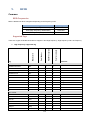
1
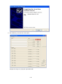
M3 MOBILE CO., LTD
M3 FAQ Guide
Version 4.1.0
Information Technology Team
1Q, 2013
Copyright © 2013 M3 MOBILE. ALL RIGHT RESERVED
735-45, M3-Bldg., Yeoksam-dong, Gangnam-Gu, Seoul, Korea 135-080
Tel. +82 2 574 0037 Fax . +82 2 574 0292
Table of Contents
Table of Contents ............................................................................................................................... 2
Revision History ................................................................................................................................. 7
1.
BATTERY ................................................................................................................................. 11
Common .......................................................................................................................................................................... 11
Battery Management and Maintenance ............................................................................................... 11
Overcharging Protection ....................................................................................................................... 13
Low Battery Warning Message ............................................................................................................ 13
M3 Battery S/N System.......................................................................................................................... 14
M3 SKY ............................................................................................................................................................................. 15
M3 Backup Battery ................................................................................................................................ 15
RTC Coin Battery ................................................................................................................................... 17
RTC Reset if Power Button is pressed for 10 seconds ..................................................................... 18
2.
BOOT ......................................................................................................................................... 19
Common .......................................................................................................................................................................... 19
How to Launch Boot Menu ................................................................................................................... 19
Reboot While Changing Battery ........................................................................................................... 21
M3 SKY ............................................................................................................................................................................. 22
Summit Booting for the First Time ...................................................................................................... 22
3.
BLUETOOTH ........................................................................................................................... 23
Common .......................................................................................................................................................................... 23
BT headset.............................................................................................................................................. 23
BT Printer................................................................................................................................................ 24
BT Stack Change ................................................................................................................................... 28
4.
GPS............................................................................................................................................. 29
Common .......................................................................................................................................................................... 29
GPS Type ................................................................................................................................................ 29
Questions about GPS ............................................................................................................................ 29
M3 SKY, M3 ORANGE ............................................................................................................................................... 30
AGManager ............................................................................................................................................. 30
5.
HARDWARE ............................................................................................................................ 33
Common .......................................................................................................................................................................... 33
Device Identification .............................................................................................................................. 33
2
M3 GREEN ...................................................................................................................................................................... 35
External Device User Guide .................................................................................................................. 35
M3 SKY ............................................................................................................................................................................. 41
How to use Windows Mobile 5.0 to M3 SKY. ...................................................................................... 41
6.
INPUT / OUTPUT .................................................................................................................... 42
M3 GREEN ...................................................................................................................................................................... 42
M3 GREEN Pin I/O Description ............................................................................................................. 42
M3 SKY ............................................................................................................................................................................. 44
M3 SKY Pin I/O Description .................................................................................................................. 44
MM3 .................................................................................................................................................................................... 46
MM3 Pin I/O Description ........................................................................................................................ 46
M3 T .................................................................................................................................................................................... 47
M3 T Pin I/O Description ....................................................................................................................... 47
M3 ORANGE................................................................................................................................................................... 48
M3 ORANGE Pin I/O Description .......................................................................................................... 48
M3 SMART ...................................................................................................................................................................... 49
M3 SMART Pin I/O Description ............................................................................................................. 49
7.
KEYPAD ................................................................................................................................... 50
Common .......................................................................................................................................................................... 50
Key Input Type ....................................................................................................................................... 50
Key Mapping .......................................................................................................................................... 55
M3 GREEN ...................................................................................................................................................................... 56
M3 GREEN Function Key Using Guide ................................................................................................ 56
M3 SKY ............................................................................................................................................................................. 60
Floating Keyboard ................................................................................................................................. 60
Launching Applications using a Button .............................................................................................. 60
M3 SKY Key Customization .................................................................................................................. 61
MM3 .................................................................................................................................................................................... 66
MM3 Key Customization ....................................................................................................................... 66
M3 ORANGE................................................................................................................................................................... 70
M3 ORANGE Key Customization ......................................................................................................... 70
M3 T .................................................................................................................................................................................... 73
3
Key Setting ............................................................................................................................................. 73
M3 SMART (WM6.5).................................................................................................................................................... 74
M3 SMART (WM6.5) Key Customization .............................................................................................. 74
8.
OS ............................................................................................................................................... 79
Common .......................................................................................................................................................................... 79
OS naming rule ...................................................................................................................................... 79
OS Update via One-click Update .......................................................................................................... 79
SD Memory Support .............................................................................................................................. 80
M3 RED / M3 GREEN ................................................................................................................................................. 81
OS Update via Mini SD Card ................................................................................................................. 81
OS Update via USB Downloader .......................................................................................................... 82
M3 SKY / MM3 ............................................................................................................................................................... 89
OS Update via (Mini) SD Card............................................................................................................... 89
OS Update via One-click Update .......................................................................................................... 91
OS Update via USB Downloader .......................................................................................................... 92
OS Update via USB in Windows 7 (M3 SKY) ....................................................................................... 96
M3 T ................................................................................................................................................................................. 100
OS Update via Micro SD Card ............................................................................................................ 100
OS Update via USB Downloader ........................................................................................................ 102
M3 ORANGE................................................................................................................................................................ 107
OS Update via MicroSD Card ............................................................................................................. 107
OS Update via USB Downloader ........................................................................................................ 108
M3 SMART WM .......................................................................................................................................................... 112
OS Update via MicroSD card .............................................................................................................. 112
OS Update via USB Downloader ........................................................................................................ 114
9.
RFID......................................................................................................................................... 119
Common ....................................................................................................................................................................... 119
RFID Frequencies ................................................................................................................................ 119
Supported Tags ................................................................................................................................... 119
10. SERIAL COMMUNICATION.............................................................................................. 122
Common ....................................................................................................................................................................... 122
COM port description .......................................................................................................................... 122
Supported Baud Rates ........................................................................................................................ 123
11. PHONE (GPRS) ...................................................................................................................... 124
4
Common ....................................................................................................................................................................... 124
Difference between EDGE and 3G ..................................................................................................... 124
M3 GREEN ................................................................................................................................................................... 125
Dialing Window .................................................................................................................................... 125
Windows Mobile (M3 SKY, MM3, M3 ORANGE, M3 SMART WM) ................................................... 127
RIL Log.................................................................................................................................................. 127
GPRS Settings ..................................................................................................................................... 129
12. SCANNER ............................................................................................................................... 135
Common ....................................................................................................................................................................... 135
Remote Desktop Connection.............................................................................................................. 135
Switching Case of Decoded Character.............................................................................................. 136
Windows CE (M3 GREEN, M3 T, M3 POS) .................................................................................................. 137
Remote Desktop .................................................................................................................................. 137
Windows Mobile (M3 SKY, MM3, M3 ORANGE, M3 SMART WM) ................................................... 138
Hotkey ................................................................................................................................................... 138
13. SOFTWARE ........................................................................................................................... 139
Common ....................................................................................................................................................................... 139
Memory Allocation ............................................................................................................................... 139
Microsoft .NET Compact Framework Version Information ............................................................. 140
Digital Signature .................................................................................................................................. 141
Windows CE (M3 GREEN, M3 T, M3 POS, M3 SMART CE) ................................................................ 150
How to use MS-Backup ....................................................................................................................... 150
How to install CAB file into M3 GREEN with new CPU .................................................................... 152
Windows Mobile (M3 SKY, MM3, M3 ORANGE, M3 SMART WM) ................................................... 153
Disable the MS customer feedback ................................................................................................... 153
SD Card Format on PDA ..................................................................................................................... 153
Installation/Launching from Storage Card ........................................................................................ 154
SMS pop-up window ............................................................................................................................ 155
Memory Size Change (M3 SKY, MM3)................................................................................................ 156
How to use WM6.5 IE as WM5.0 IE ..................................................................................................... 157
14. WLAN ...................................................................................................................................... 159
Common ....................................................................................................................................................................... 159
Summit Client Utility (SCU) Profile Saving ....................................................................................... 159
Summit Client Utility (SCU) Summary ............................................................................................... 160
5
Summit WLAN Domain Change ......................................................................................................... 165
WLAN Connection during ActiveSync .............................................................................................. 165
WLAN Roaming .................................................................................................................................... 166
How to set different language on SCU .............................................................................................. 167
M3 SKY / MM3 ............................................................................................................................................................ 168
Ad-hoc Mode ........................................................................................................................................ 168
WLAN re-connection after sleep mode ............................................................................................. 169
15. Others....................................................................................................................................... 170
Common ....................................................................................................................................................................... 170
Background Image .............................................................................................................................. 170
Backlight and TimeOut Control .......................................................................................................... 172
User Power Mode(LCD, Touch and keypad disable instead of sleep mode) ................................ 173
M3 Reset / Boot Glossary ................................................................................................................... 176
Setting date and time on the PDA automatically .............................................................................. 178
6
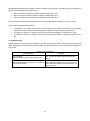
Revision History
Release Notes Ver 4.1.0
-
All invalid links are fixed.
-
WLAN roaming issue has been fixed by newest SCU version.
-
Key Mapping section updated.
-
UPM(User Power Mode) added for M3 Orange, M3 SKY and MM3.
-
M3 Green and T can use different sleep conception as similar as UPM.
Release Notes Ver 4.0.4
-
Added method of using WM5.0 for M3 SKY
-
Added method of adopting WM5.0’s IE style to higher version of WM.
Release Notes Ver 4.0.3
-
Added GPRS connection setting Method through XML.
-
RFID (UHF) support tag type added.
-
Added CAB file install method for M3 GREEN with new CPU.
-
Added Soft Key registry changing setting.
-
Added note for ‘How to obtail Rillog’ section.
Release Notes Ver 4.0.2
-
Added M3 SMART Key Customization (M3.ini, VisualINI, Registry methods)
Release Notes Ver 4.0.1
-
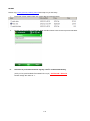
Bluetooth Printer pairing method has been replaced.
Main Category
Bluetooth
GPS
FAQ Topic
Bluetooth Printer paring method has been replaced from
MS-Stack base to Stone Street Stack
Note has been added
Release Notes Ver 4.0
-
Fixed links and re-categorized some FAQ Topics as shown below.
-
Added / Modified below FAQ topics
7
Main Category
Bluetooth
Keypad
OS
RFID
Serial Communication
Software
WLAN
-
FAQ Topic
BT Stack Change
MM3 Key Customization
M3 ORANGE Key Customization
M3 SMART WM Key Customization
M3 SKY OS Update via USB in Windows 7
M3 ORANGE OS Update via MicroSD card
M3 ORANGE OS Update via USB Downloader
M3 SMART OS Update via MicroSD card
M3 SMART OS Update via USB Downloader
External Memory Support
Tag type that RFID supports
Supported Baud Rates
M3 Series Compact Framework Version
Digital Signature - Modified
ReformatUtil for M3 SKY, MM3
How to set different language on SCU
Removed old / useless articles that do not apply to M3 PDAs anymore.
Release Notes Ver 3.1.1
-
Fixed bugs: broken links, hidden pages.
Release Notes Ver 3.1
-
Added below FAQ topics
Main Category
Input / Output
OS
-
FAQ Topic
MM3 POGO Pin Description
M3 ORANGE OS Update Manual (USB / SD)
Combined common documents into one simplified version
Before
WLAN Roaming
Roaming between APs – Summit WLAN
After (Merged)
WLAN Roaming
Release Notes Ver 3.0
-
Added below FAQ topics
Main Category
GPS
FAQ Topic
Questions about GPS
AGManager (GPS Application)
8
Input / Output
Keypad
OS
Phone (GPRS)
Scanner
WLAN
M3 ORANGE POGO Pin Description
Key Mapping for M3 Products
Key Input Type Recognition on M3 SKY, M3 ORANGE
M3 SKY QWERTY Keypad Functions
M3 T Key Settings
OS Update via One-click Update (easy update)
OS Naming Rule
Differences between EDGE and 3G
GSM/GPRS Information
Scanning Problem in RDP
WLAN Setting
WLAN Re-connection after Sleep Mode
Ad-Hoc Mode in SCU
Release Notes Ver 2.0
-
FAQ documents on Flash Disk applications such as ScanEmul, RfidEmul is removed from previous
version of M3 FAQ Guide and released a separate Application Manual.
-
GPRS category is changed to Phone (GPRS)
-
Added below FAQ topics
Main Category
Battery
Boot
Bluetooth
Camera
GPS
Hardware
Input / Output
OS
Phone (GPRS)
Scanner
Serial Communication
Software
FAQ Topic
Overcharging Protection
Reboot
BT Headset
Zebra Printer
Bluetooth Printing
Camera Button on M3 SKY
GPS Type of M3 SKY
Device Identification
SD Card Format
M3 GREEN POGO Pin Description
M3 SKY POGO Pin Description
Supported SD Capacity for OS Update
Roaming Frequency between 2G and 3G
Dialing Window
Phone Book Entry
Ril Log
Remote Desktop Connection
Hotkey
COM port Type
Serial Port
Digital Signature
.Net CF Version
Memory Allocation
Preventing RDP Disconnection
Keyboard Management
ActiveSync
9
WLAN
ETC
Installation / Launching from Storage Card
Disable MS Customer Feedback Message
SMS Pop-Up Window
SCU Profile Saving
PAP / CHAP Set Up
Summit WLAN Domain Change
WLAN Roaming
Wireless Issue
SCU Update
Setting Date and Time through ActiveSync
Background Image
Backlight Timeout control
10
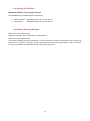
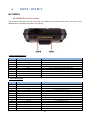
1.
BATTERY
Common
Battery Management and Maintenance
You can maximize the battery life with a little bit of care. Since the batteries are chemical devices, it is
important to keep the electron in it flowing occasionally. If the battery is stored in fully discharged state for a
long period, it could fall into a deep discharge state. On the other hand, if the battery is stored in fully
discharged state for a long period, the total battery capacity may be reduced. Please read the following tips
to maximize the battery life.
1. PDA Settings
Turn off unnecessary functions - Functions such as Wi-Fi, Bluetooth, GPS, etc will drain more power from
the battery. If you rarely use such functions, please turn off to save power. To turn off each function, assist
the main manual.
Reduce brightness of the backlight - Brighter backlight will consume more power. Setting the backlight as
low as possible is another way to save power. To adjust the backlight level, assist the main manual.
Enter suspend mode - Entering suspend (sleep) mode when you are not using PDA can increase the
battery life. To enter suspend mode or to set auto-suspend mode, assist the main manual.
2. Charging Tips
The battery pack should be fully charged before you use the PDA for the first time. Within the acceptable
temperature range, it will take approximately 4 hours to fully charge from deplete state using the supplied
charging cradle.
Acceptable Charging Temperature Range
Charging Temperature Range
-20C (-4F) ~ 60C (140F)
Use correct battery and charger for your device - Use of incorrect battery or charger may degrade battery
performance and reduce the battery lifespan.
Assign one charging cradle to each device - Sharing a charging cradle among users is a common
practice. However, sharing the charger may cause the user to pick up a battery that may have not been fully
charged. We recommend assigning a cradle to each device to make sure the battery is fully charged. Green
LED indicated the battery is fully charged.
Charge the battery when prompted - You will get an audible alert with a pop-up message when the battery
is low. Failure to charge the battery may consume all RTC power and system time will reset to default. When
main battery is detached, the RTC battery will keep the system time information for as long as 5 minutes.
Use 2 batteries supplied alternatively - You can increase the battery lifespan by using 2 batteries
alternatively. If you are carrying a spare battery, we recommend charging the spare battery up to about 80%
of its full capacity. More batteries may be used for more reliability.
Clean the battery contact surfaces regularly - Dirty contact points are a main source of charging problems.
Regular cleaning is required for optimal performance. When cleaning it, please use a soft cloth. Cleaning
with liquid material is not recommended. (Pure alcohol may be used.)
3. Charge Cycles
11
Rechargeable batteries have a limited number of charge cycles and may eventually need to be replaced. A
properly maintained battery can retain up to:
•
•
•
90% of its original capacity at 100 full charge and discharge cycle.
85% of its original capacity at 300 full charge and discharge cycle.
80% of its original capacity at 500 full charge and discharge cycle.
You may choose to replace your battery when it no longer holds sufficient charge to meet your needs.
We recommend replacing the battery if:
•
•
•
The battery is more than 2 years old. The first 2 digits of the 4-digit serial number on the battery
represent the year of manufacture and the other 2 digits represent the date of manufacture.
The battery is used for 17 months in an environment where the battery is charged once a day.
The battery is used for 10 months in an environment where the battery is charged more than once a
day.
4. Troubleshooting
A weak battery can cause an error message to appear on your device. Before sending your product out for
repair, please ensure the battery is working properly. Following are some common errors that may appear on
your device:
Common Error Message
Error Message
Device is dead.
(Display is blank or the unit will not power on)
Solution
Try to cold boot the terminal first. If this does not
work, replace the battery with a known good
battery.
The main battery is low. Please replace the
Battery low message is popped up or the device battery with fully charged one. If this leaves the
goes off while booting.
device without charging or replacing battery, the
data can be lost.
12
Overcharging Protection
Main/backup battery overcharging protection
All M3 batteries are protected against overcharging.
Back-up battery: Integrated PCM circuit / Cut off at 2.8V
Main battery:
Integrated PCM circuit / Cut off at 2.8V
Low Battery Warning Message
When 20% of full capacity is left:
Displays a message, 'Not enough battery', at the task bar.
When 10% of full capacity is left:
The caution message pops up several times. From this moment, the device consumes the 10% of charge to
keep it alive. If all 10% is consumed, it enters sleep mode and uses the back-up battery. If all is consumed,
the device is powered off and all data except in flash disk may be lost.
13
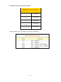
M3 Battery S/N System
Battery serial numbering system was changed for batteries produced after 11th Dec 2009 for internal
management reason. However, it has been rolled back to the original system since Feb 2010.
*P/N and S/N are indicated inside the battery socket.
Original Battery Numbering System
•
•
Batteries were recorded according to the manufacture date. Ex) 0906 means it was manufactured in
June 2009.
Problem - If batteries are stored in warehouse for a reasonably long time, the numbering system
may lead the customers to misunderstanding. They might think the battery’s guaranteed life
(normally 6 months) time has been expired and induces unnecessary management.
Modified Battery Numbering System
•
•
•
Use alphabet instead of numbers. Ex) AIL for batteries manufactured in Dec 2009.
Using alphabetical serial number eliminates the problem of the original system.
Effective since 11th Dec 2009.
A
B
C
Production Lot
1st
2nd
3rd
Year
2001
2002
2003
Month
Jan
Feb
Mar
Cell Type
S
U
Production Lot: Monthly Supply Lot
Year / Month: Continue to Z and start over
Cell Type: S: SDI U:SANYO
D
4th
2004
Apr
E
F
G
H
I
J
K
L
~Z
2005
May
2006
Jun
2007
Jul
2008
Aug
2009
Sep
2010
Oct
2011
Nov
2012
Dec
~
Ex) AILS refers to 1st production lot manufactured in Dec 2009 with SDI cell.
Current Battery Numbering System (July 2010)
•
•
Current battery numbering system has been rolled back to the original system since Feb 2010 due to
alteration in national KC certification.
Battery serial numbers are recorded according to the manufacture date.
14
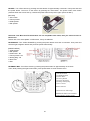
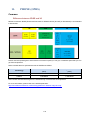
M3 SKY
M3 Backup Battery
Real Time Clock (RTC) Summary
A secondary backup battery is integrated in all M3 SKY terminals. The secondary battery is used to keep the
time and date information while changing the main battery. However, its functionality varies according to its
model and the version of main board.
In early models of MC-7XXXS, a small real time coin battery was included as shown on the below left picture.
<Old Version>
<New Version>
Left figure shows integrated (soldered) RTC coin battery and the right figure shows a detachable backup
battery.
In main boards v1.1 (MC-71XXS), v2.1 and v2.2 (MC-75XX/77XXS), the coin battery is charged through
system power. Hence, if the terminal is turned off by pressing the power button for 10 seconds, the system
stops operating and consequently the coin battery is not working. Therefore, the RTC is reset.
To charge the coin battery, the main battery must be attached to the device AND the device is switched on. If
the PDA is not switched on, the coin battery is not charging even if the main battery is attached. Moreover,
placing the turned off terminal on the cradle will NOT charge the coin battery.
To prevent RTC reset, you must not turn off the terminal by pressing the power button for 10 seconds.
In main board v1.2 (MC-71XXS), the coin battery is charged through the main battery and it follows the main
battery level. Hence, turning off the terminal by pressing the power button for 10 seconds will not reset the
time information. But leaving the device at off state for longer than 5 minutes will reset RTC and GPS data
because a fully charged coin battery is only able to keep RTC and GPS data for 5 minutes. This also implies
that stored data will reset if the main battery is detached for longer than 5 minutes.
As improvement of the backup battery system is necessary, M3 Mobile re-designed the backup battery
15
system and it has been applied to the terminal when M3 Mobile adopted new Summit WLAN module. Below
table describes the key differences between the previous M3 SKY terminals and M3 SKY terminals with the
new backup battery system.
Main board version history
Power off using the power button
(long time)
M3 SKY (Samsung)
RTC Coin Battery
MCMC-71XXS
75XX/77XXS
v1.1
v2.1
v1.2
v2.2
RTC reset (v1.1)
RTC and GPS satellite data kept
for approx. 5 min (v1.2, 2.1, 2.2)
M3 SKY (Summit)
Backup Battery
MC-71XXS
MC75XX/77XXS
v2.1
v2.3
Keeps RTC and GPS satellite
information up to 50 hrs
Detaching the main battery from
power on state
RTC kept for approx. 5 min
Auto sleep mode,
force shut down phone
Hard reset / Long reset
RTC reset
RTC reset
Coin / Backup battery capacity
0.22 F (Capacitor)
200 mA
Charging method
v1.1, v2.1, v2.2
- Attach fully charged main battery
- Turn on the terminal
v1.2
- Attach fully charged main battery
- Attach fully charged main battery
Time taken to fully charge the
coin / backup battery with fully
charged main battery
Approx. 30 minutes
Approx. 30 minutes
16
RTC Coin Battery
RTC Reset Causes and Prevention - M3 SKY with RTC Coin Battery
RTC coin battery is integrated in a few models of M3 SKY. The coin battery is used to keep the device alive
while changing the main battery. By ‘alive’, we mean the device does not lose any information stored in the
device including the time information. However, the device will go to sleep mode.
A fully charged RTC coin will keep the device alive for around 5 minutes. If the main battery is detached for
longer than 5 minutes, the time information is lost.
Another scenario that the time information is lost is that when the PDA is completely powered off (turning off
the device by pressing the power button for 10 seconds) for longer than 5 minutes. This is because when the
device is completely powered off, the RTC coin battery is working to keep the time information and after 5
minutes, it is fully discharged and all the unsaved information will be lost.
To prevent RTC reset, DO NOT power off the device by pressing the power button for 10 seconds (except in
the case of special event such as upgrading OS or clean boot) or detach the main battery from the device
and leave the device for a long time. Current in the RTC coin battery is flowing when the device is completely
powered off and it may result in RTC information loss. If you must detach the main battery for whatever
reasons, please place the device on the cradle.
To charge the coin battery, the main battery must be attached to the device AND the device is switched on. If
the PDA is not switched on, the coin battery is not charging even if the main battery is attached. When a fully
charged main battery is attached to the device, it will take approximately 20 minutes to charge the coin
battery.
17
RTC Reset if Power Button is pressed for 10 seconds
Old models of SKY have Real Time Coin battery as a back-up battery as shown below.
Ways to charge the battery vary according to the main board version.
For V1.1: Charged through CPU, and RTC is reset if the power button is pressed for 10 sec.
For V1.2: Charged through the main battery and follows the main battery level.
Fully charged back-up battery can keep the date information and GPS configurations for 5 to 10 minutes
without the main battery.
18
2.
BOOT
Common
How to Launch Boot Menu
M3 RED / GREEN - Does not support boot menu
M3 SKY - Turn off M3 SKY by pressing the power button for 10 seconds. Then while pressing the right
directional button, turn on the device by pressing the power button.
[MBOOT MENU]
1. Update
2. Format All
3. Device ID
4. Clean Boot - No
5. Factory Reset
Enter. Select
0. Exit (Boot)
MBoot
v3.1.3_[520Mhz/128MB]
MM3 - Turn off MM3 by pressing the power button for 10 seconds. Then while pressing the right directional
button, turn on the device by pressing the power button. (Same as M3 SKY)
[MBOOT MENU]
1. Update
2. Format All
3. Device ID
4. Clean Boot - No
5. Factory Reset
6. Debug Serial - No
Enter. Select
Exit (Boot)
M3T - Turn off the device by pressing the reset button for approximately 5 seconds. Then press and hold the
power button. Then turn on the device by pressing the reset button. The power button must remain pressed.
When the screen fires up, release the power button and press it again.
[MC-6700]
1. OS Launch
2. USB Update
3. SD Update
4. Factory Reset
5. EBOOT Config
19
M3 POS - Turn off the device by pressing the reset button for approximately 5 seconds. Then press and hold
the power button. Then turn on the device by pressing the reset button. The power button must remain
pressed. When the screen fires up, release the power button and press it again. (Same as M3 T)
[M3 POS]
1. OS Launch
2. Factory Reset
3. USB Update
4. SD Update
Note that if the Boot and OS information are not compatible each other, then you cannot access to
Boot menu.
Please refer "One-click Update" of OS section, if they are different.
M3 ORANGE - Turn off M3 ORANGE by pressing the power button more than 10 seconds. Then press and
hold the right navigation button and press the power button briefly.
[PBOOT MENU]
1. USB Update
2. SD Update
3. Clean Boot - No
4. Factory Reset - No
5. Debug Msg - No
6. Device ID
0. Exit
M3 SMART WM - Turn off the device by pressing the power button for approximately 10 seconds.
Then, while pressing the right arrow button, press power button to enter the boot menu.
[BOOT MENU 1.0.2]
1) SD Download
2) USB Download
3) Clean Boot
4) Factory Reset
5) Device ID(UUID)
6) Debug Serial:[NO]
7) ALL Format
Select Number
0) Exit:Launch OS image
SAMSUNG-S5PC100 833MHz
RAM 256MB / ROM 512MB
20
Reboot While Changing Battery
When the main battery is detached, the device goes to sleep mode. During the main battery replacement,
the backup battery is activated to keep the system alive.
However, if the back-up battery is empty or dead, the PDA does not have a backup power to keep it alive,
result in restart of the PDA when the main battery is replaced.
21
M3 SKY
Summit Booting for the First Time
New M3 SKY MC-7xxS with Summit WLAN module has a backup battery rather than a RTC coin battery.
When booting the device for the first time, must reset the CPU by power-cycle before power it on. Without
CPU reset, the device may not turn on due to low back-up battery which is discharged during shipping.
It is designed to act like that; not a faulty device.
To reset the CPU, please follow two steps below:
1. Attach fully charged main battery or connect the AC power cable to the device.
2. Press and hold the reset button for at least 5 seconds.
3. It will automatically reboot. Otherwise, press the power button.
22
3.
BLUETOOTH
Common
BT headset
What type of BT headset is available for M3 SKY?
BT function has limitation in WM5.0 because of using MS stack. By upgrading WM5.0 to WM6.1 which is
using StoneStreet1 stack, BT headset function is supported.
M3 Mobile has tested with products of Sony (HBH-DS970) and Plantronics (Voyager 520).
HBH-DS970
Voyager 520
23
BT Printer
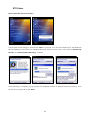
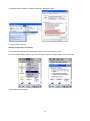
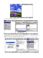
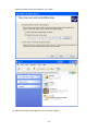
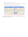
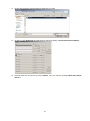
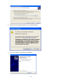
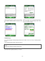
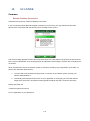
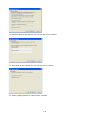
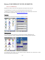
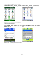
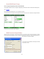
How to pair M3 with a BT Printer?
Choose service that willing to use and click ‘Next’ to proceed, if it’s first time searching for the Bluetooth
devices, BTExplorer will search for available Bluetooth devices around, and it will produce ‘Discovering
Devices’ and ‘Remote Name Discovery’ windows.
Once searching is complete, pop-up window will disappear and list of devices found will come up, from
the list choose printer and click ‘Next’.
24
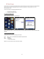
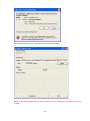
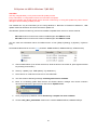
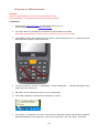
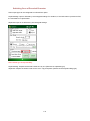
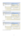
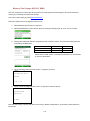
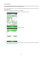
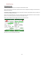
‘PIN Code Request’ window will pop-up, enter identical Pin Code that BT printer has.
If the Pin Code entered is identical with BT printer’s Pin Code, ‘Select Remote Service’ window will popup, choose service and click ‘Next’.
‘Connection Favorite Options’ window will pop-up, user can either check or edit device’s name,
25
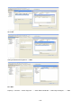
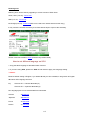
address and service name. Click ‘Next’.
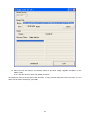
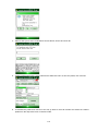
‘Connection Summary’ window that pop-up, allows users to check details of connection.
‘Remote Service Connection’ window will pop-up, user may change ‘Service Type’ and ‘COM Port’.
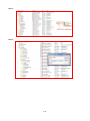
26
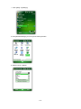
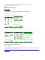
Once the Connection is made, ‘Favorite’ will be shows up, and Bluetooth icon will be change (
27
).
BT Stack Change
M3 SKY, MM3, M3 ORANGE, M3 SMART WM provides dual Bluetooth stacks: MS stack and StonstreetOne
stack. User can choose the appropriate stack to suite their application. Factory default is set to use
StonestreetOne stack.
There are two ways for changing the Bluetooth stack.
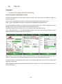
1. Using Windows Mobile GUI
2. Changing the Registry Value
Using Windows Mobile GUI
[Start] [Settings] [Systems] [BT Select]
From the BT Select option, choose the stack that you want and make a soft reset to make the new BT stack
affective.
Changing the Registry Value
Default stack can be chosen by modifying the registry.
Path:
Key:
Value:
HKEY_LOCAL_MACHINE\Software\Mobilecompia\bluetooth
Thirdparty
0 – MS Stack
1 – StonstreetOne Stack
Make sure you soft reset the device after stack change.
28
4.
GPS
Common
GPS Type
What type of GPS is used in M3 PDAs? Does it support A-GPS?
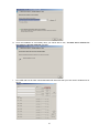
M3 uses two different modules for GPS. Please refer below table for GPS chipsets.
Model
GPS Chipset
M3 SKY
M3 ORANGE
M3 T
SiRF Start III
M3 SKY
MM3
M3 SMART
M3 ORANGE
UBLOX(AGPS
supported)
PDAs that use SiRF Star III do not support A-GPS (Assisted GPS). However, it is supported in the M3 SKY,
M3 ORANGE since 2Q 2012.
Questions about GPS
1. When does the GPS module start gathering GPS data?
When the power is supplied to GPS module and COM2 is opened, GPS starts to work regardless of running
OS. It only works when COM Port is opened at certain program.
2. How long does battery last while turning on GPS?
Battery will last for about 9 hours when using standard battery and Level 5 of backlight. It may vary
depending on its usage environment.
29
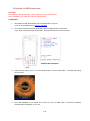
M3 SKY, M3 ORANGE
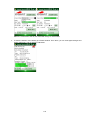
AGManager
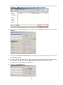
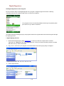
AGManager is a GPS test program for Sirf III only. To test GPS, download below linked AGManager file and
unzip it. To install this program, please follow below steps.
AGManager : Download
1. Move to
Start\Settings\System\Screen to
align screen first.
2. Check at ‘Landscape (righthanded)’ and click ‘Align Screen’
button.
After aligning screen, it will turn to below picture.
30
3. Launch AGManager program and select COM2 then click OPEN button. It will start gathering GPS data.
If you get the fixed satellites more than 4, you can get the position by latitude and longitude.
And there are three types of GPS reset - cold, warm and hot. Reset means re-positioning of its location.
Cold reset: A condition in which the GPS receiver can arrive at a navigation solution without initial
position, time, and current Ephemeris.
Warm reset: Start mode of the GPS receiver when current position, clock offset, and approximate
GPS time are input by the user. Ephemeris data is not available.
Hot reset: Start mode of the GPS receiver when current position, clock offset, approximate GPS
time, and current ephemeris data are all available.
* Note: Sometimes when internal battery is dead PDA with Sirf III module, default setting of NMEA Protocol
changes to Sirf Binary Protocol, if GPS is suddenly not working, please change this setting back to NMEA
using AG Manager.
31
32
5.
HARDWARE
Common
Device Identification
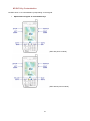
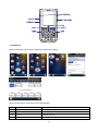
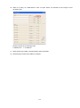
How to use P/N to Identify Device Options
The user of M3 Mobile handheld terminal can use the product number (P/N) to identify the device option
such as Scanner, WLAN, WWAN, etc. The P/N is normally indicated inside the battery socket as indicated in
the figure.
Please refer to below table to learn how to read P/N.
Note that this table is only valid for products manufactured after September 2010.
Indices Character
1st
Interpretation
Remarks
A
MC-6000S
Discontinued.
B
MC-6200S
M3 RED
C
MC-6300S
M3 GREEN
D
MC-6400S
M3 GREEN (HW decoder)
E
MC-6500S
M3 GREEN
F
MC-6600S
Discontinued.
G
MC-7700S
M3 SKY (2D Scanner)
H
MC-6100S
Discontinued.
I
MC-7100S Summit
M3 SKY (Summit WLAN)
J
MC-7100S
M3 SKY (Samsung WLAN)
K
MC-7500S
M3 SKY (Samsung WLAN)
M
MC-1000S
M3 BLACK
N
MC-6700S
M3 T
O
MC-8000S
MM3
P
MC-8800S
M3 POS
R
MC-7500S Summit
M3 SKY (Summit WLAN)
S
MC-7700S Summit
M3 SKY (2D Scanner, Summit WLAN)
33
2nd
3rd
CPU
/ ROM
4th
WWAN
5th
6th
Options
7th
RFID
8th
Year
9th
Month
U
MC-10
TA
MC-7100S Telstra
Q
M3-20
M3 ORANGE
A
xx00S
Alpha-numeric keypads
B
xx10S
RFID Module
C
xx20S
RFID Module
D
xx30S
RFID Module
K
xx00S QWERTY
QWERTY keypads
L
xx10S QWERTY
QWERTY keypads and RFID module
1
400 / 64
2
400 / 256
3
520 / 64
4
520 / 128
5
520 / 256
6
624 / 256
7
806 / 256
8
806 / 1G
9
833 / 512
10
833 / 1G
G
GSM
H
HSDPA/HSPA+(for Smart only)
M
CDMA
N
N/A
P
PCS
C
CF
G
WLAN & GPS
N
N/A
M3 SMART
P
GPS
SirF III, UBLOX(AGPS)
W
WLAN
Samsung or Summit
A
S
S: Scanner
B
SC
C: Camera
C
SB
B: Bluetooth
D
SCB
E
CB
F
B
G
C
H
N/A
A
13.56 MHz (Ceyeon)
Ceyeon RFID Module
B
13.56 MHz (Telefunken)
Telefunken RFID Module
C
13.56 MHz (M3 Mobile)
M3 Mobile (HID) RFID Module
U
800 MHz(UHF)
CAEN
N
N/A
L
LF
M3 Mobile(HID) RFID Module
L
2012
Manufactured in 2012
M
2013
Manufactured in 2013 and so on...
A
January
Manufactured in January
B
February
Manufactured in February and so on...
Last five digits are identification serial codes.
34
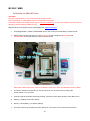
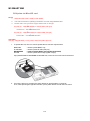
M3 GREEN
External Device User Guide
System Block between M3 GREEN (MC-6510S) and External Device
Host Interface Connector [MC-6500S]
Production: Kyocera-elco http://www.kyocera-elco.com
Part Type : FPC Connector
Part Name: 0.5mm Pitch RA SMT Bottom contact One-touch lock
MC-6500S to External Device FPC Cable
Production
Part Type
Part Name
Part Number
: KFC Electric
: FPC Cable
: 0.5mm Pitch Top/Bottom cross contact
: KF16 06/07 S5 B1 VS1 VB1
Configuration of FPC Cable to Connect External Device
35
* As you see in the above picture, the FPC cable to connect with external device is exposed to outside to use.
* Space for external device is 38.1(w) x 59.9(h) x 8.3(d).
Host Interface Connection Pin Out
* Mode (Mode 1 or Mode 2) can be selected by user. The manual to do this please refer to the 9th item on
the end of this section.
PIN Signal
I/O
PDA
Idle
1
MBATT
-
-
2
RX
(COM8)
I
Application
Running
PDA
Sleep
PDA
Wakeup
Application
End
Low Battery
or
Description
Battery Pack
Detached
-
-
-
-
-
Input-TTL level 232
receive data
(3.3V~ 0V)
Close Open
3
Close
Open
Close
Close
Output-TTL level 232
transmit data
(3.3V ~ 0V)
TX(COM8) O
It is controllable by user’s application.
It is Low by default, and the reset time can be controlled by user.
RESET
O
Low
Mode1
4
5
PWR_EN
O
Power-Supply voltage
output.
Range 3.6 ~ 4.2V
Low
High
OS keeps
the status
before
sleep
(make it
Low from
High is
possible by
driver)
OS will
keep the
status
before
sleep
36
Application
should make
it low
[a]
User Application control
*KernelIoControl is
provided
(refer to the 5th item)
Output -high signal (3.3V)
(By installing driver, pin
status can be
set as Low at PDA Sleep)
* Driver (.dll file) is
provided
(refer to [b])
* KernelIoControl is
provided
(refer to the 3rd item)
Output- User Application
control is active high
signal (3.3V)
Serial port buffer = to
switch between ext device
and ext serial because the
COM8 is shared.
* High signal: Buffer on
* Low signal: Buffer off
DTR
O
Low
OS makes
it Low
OS keeps
the
status
before
sleep
Application
should close
the COM
port
M
4
High
(Port should
be open)
Output- Active high signal
(3.3V)
Depending on the status
of COM Port, OS handles
DTR pin as below.
* When COM Port is
Opened, DTR is High
* When COM Port is
Closed, DTR is Low
5
NC
-
6
GND
-
-
-
-
-
-
-
This pin cannot be used
* There should be no
circuit connection.
Therefore, it should be
open at the External
Device.
-
-
-
-
-
Power- Supply and signal
ground.
[a]: When Battery is low or battery pack is detached, PDA goes to sleep after displaying "battery runs out or
battery pack is detached".
: At this moment, application should close the COM Port and cut the power to the External Device (Refer to
the technical document we provided in the past) by receiving below event.
Namely, COM port: close and PWR_EN: off
* PWR_EN: Driver should set the pin status of PWR_EN to low to disable the serial buffer for preventing
possible leakage current.
* In the case of battery detached or low battery
- Things to do in the application
#define WM_BATTERY_OFF WMUSER+4955
case WM_BATTERY_OFF:
[b]: In order to set the pin status of PWR_EN to Low, the provided driver should be loaded using below code
in the application.
HANDLE hPWRDevice;
HANDLE hPWR= 0;
hPWRDevice=RegisterDevice(
TEXT("XXX"), //device identifier prefix
1, //device identifier index
TEXT("pwrdrv.dll"), //device driver name
0); //instance information (passed to XXX_Init)
if (hPWRDevice)
{
hPWR=CreateFile(_T("XXX1:"),
37
GENERIC_READ | GENERIC_WRITE,
0, //must be opened with exclusive-access
NULL, //no security attributes
OPEN_EXISTING, //must use OPEN_EXISTING
0,
NULL; //hTemplate must be NULL for comm devices
if (!hPWR)
{
return;
}
}
else return;
//this is just an example code (XXX represents the module name).
1. MBATT
Supply the power of Min 3.6V ~ Max 4.2V from PDA main battery.
2. TX/RX [TTL Level 232]
PDA COM Port to use is COM8 and it is 3.3V in TTL Level.
Note: It is difficult to use 230K or 460K baud rate because there is no hardware flow control. Hence, 115.2K
is recommended.
3. PWR_EN [Power Enable]
It can be controlled in the user's application to control the power of external module (refer to the source
code).
* In the case of powering up the External Device
- Things to do in the External Device Driver
1) Please define as below
#define IOCTL_HAL_PWR_SEL
FILE_ANY_ACCESS)
CTL_CODE
(FILE_DEVICE_HAL,
2) Power Set Low (To confirm that it is low)
ucSel = 0;
KernelIoControl(IOCTL_HAL_PWR_SEL, &ucSel, 1, NULL, 0, NULL);
Sleep(100);
3) Power Set High
ucSel = 1;
KernelIoControl(IOCTL_HAL_PWR_SEL, &ucSel, 1, NULL, 0, NULL);
Sleep(250);
* In the case of powering down the External Device
1) Power Set Low
38
2118,
METHOD_BUFFERED,
ucSel = 0;
KernelIoControl(IOCTL_HAL_PWR_SEL, &ucSel, 1, NULL, 0, NULL);
4. DTR [Data Terminal Ready]
The DTR signal is sent via a dedicated wire from the transmitting PDA to the transmission device to indicate
that the PDA is ready to receive data.
5. RESET
Reset is controlled by the below KernelIoControl.
1) Reset Set High
ucSel = 0;
KernelIoControl(IOCTL_HAL_PWR_SEL, &ucSel, 1, NULL, 0, NULL);
Sleep (xxx) //this is to control the reset time, so please give the required sleep time between high and low.
2) Reset Set Low
ucSel = 1;
KernelIoControl(IOCTL_HAL_PWR_SEL, &ucSel, 1, NULL, 0, NULL);
6. PDA Idle
It is standby mode and Idle Current is below 200mA.
7. PDA Sleep
It is power saving mode and the Sleep Current is below 10mA.
This is an example code of when the device goes to sleep, system will power down your module (this is with
assumption that you power off your model at device sleep).
* In the case of PDA going to sleep
- Things to do in the External Device Driver
extern "C" _declspec(dllexport)
void XXX_PowerDown(DWORD hDeviceContext)
{
XXX_Power(FALSE);
return;
}
//this is just an example code (XXX represents the model name).
8. PDA Wakeup
This is an example code; you need to send a message to the application that the device is active again.
* In the case of PDA Wakes Up
- Things to do in the External Device Driver
void XXX_PowerUp(DWORD hDeviceContext)
39
{
PostMessage(
HWND_BROADCAST,
WM_POWERUP,
NULL,
NULL
);
return;
}
//this is just an example code (XXX represents the module name).
- Things to do in the application
case WM_POWERUP:
When you get this message, you need to power up your module and reinitialize it.
9. How to select Mode
In M3.ini file, you can find the label called [EXT_MODE2].
Value of '0' means enable MODE1.
Value of '1' means enable MODE2.
10. Disabling IrDA
Since the external device uses IrDA port, it should be disabled in M3.ini.
In M3.ini file, you will find a label called [IRDA_INIT].
Please assign '0' to its install value.
40
M3 SKY
How to use Windows Mobile 5.0 to M3 SKY.
M3 SKY used to use Windows Mobile 5.0 as its operating system but it’s been replaced by Windows Mobile
6.x now. M3 Mobile therefore does not support Windows Mobile 5.0 anymore, however there are still number
of customers wish to use Windows Mobile 5.0, and they may be able to swap their Operating system to
Windows Mobile 5.0, if their device fulfill conditions mentioned below.
Notice: To be able to perform above method, the first digit of your KEY PCB version information must
be ‘1’.
If device’s Main board version matches with its CPU board version you may downgrade your device to use
Windows Mobile 5.0, to get OS and method of doing it please contact ITC page.
41
6.
INPUT / OUTPUT
M3 GREEN
M3 GREEN Pin I/O Description
This document describes the type and usage of 9 POGO Pin connectors and 24 Pin connector of M3
GREEN which is located at the bottom of the device.
1. POGO PIN Description
No.
Name
Connect Information
1
USB_DN
For USB data negative
2
USB_DP
For USB data positive
3
USB_PW
For USB power
4
DETECT
Active High
5
RXD
PDA -> DCE (TTL level), Serial RXD COM8
6
TXD
PDA <- DCE (TTL level), Serial TXD COM8
7
USB_DETECT
For USB
8
CHR_MNS
GND
9
+5V
System Power and Charging
No.
Name
Connect Information
1
RSV
2. 24 Pin Description
2
RSV
3
USB_HOST_DETECT
Detect for USB Host (Low Active)
4
+5V
System Power and Charging
5
+5V
System Power and Charging
6
TDI
KEY_CPLD
7
TMS
KEY_CPLD
8
TCK
KEY_CPLD
9
TDO
KEY_CPLD
10
USB_DN
For USB data negative
11
EXT_SERIAL DETECT
Active High
12
GND
Power Ground
13
EXE_SERIAL_RXD
PDA <- DCE (TTL level)
14
EXE_SERIAL_TXD
PDA -> DCE (TTL level)
42
15
USB_DP
For USB data positive
16
USB_PW
For USB power
17
DM_RXD
CDMA
18
DM_TXD
CDMA
19
GND
Power Ground
20
DM_DETECT
CDMA DM Port Enable (High Active)
21
BATT
Battery Line (MAX. 4.2V)
22
BATT
Battery Line (MAX. 4.2V)
23
RSV
24
GND
Power Ground
43
M3 SKY
M3 SKY Pin I/O Description
This document describes the type and usage of 9 POGO Pin connectors and 24 Pin connector of M3 SKY
which is located at the bottom of the device.
1. POGO PIN Description
No.
Name
Connect Information
1
USB_DN
For USB data negative
2
USB_DP
For USB data positive
3
USB_PW
For USB power
4
DETECT
Active Low
5
RXD
PAD -> DCE (TTL level), Serial RXD COM8
6
TXD
PDA <- DCE (TTL level), Serial TXD COM8
7
TOGID
DC 3.6~4.2V
8
CHR_MNS
GND
9
+5V
System Power and Charging
No.
Name
Connect Information
1
TRST
2
TMS
PRE_PWR
3
TCK
USB_OTGID
4
TDI
DC 5V
5
TDO
DC 5V
6
RXD
JTAG_TDI
7
TXD
JTAG_THS
8
RTS
JTAG_TCIC
9
CTS
JTAG_TDO
10
USB_DN
For USB data negative
11
GPS_DETECT
Active High
12
BATT_MNS
13
RXD2
PDA <- DM_TXD
14
TXD2
PDA -> DM_RXD
15
USB_DP
For USB data positive
16
USB_PW
For USB power
17
DM_RXD
CPU_TRST
18
DM_TXD
TEXT_POINT
2. 24 Pin Description
44
19
BATT_MNS
20
DM_DETECT
Active High
21
BATT
Battery Line (MAX. 4.2V)
22
BATT
Battery Line (MAX. 4.2V)
23
IGT
GSM ON/OFF
24
GND
Power Ground
45
MM3
MM3 Pin I/O Description
This document describes the type and usage of 16 Pin connector of MM3 which is located at the bottom of
the device.
1. 16 PIN Description
No.
Name
Connect Information
1
5V
System Power and Charging
2
5V
System Power and Charging
3
USBC_PW
USB Client PWR
4
USBC_DN
USB Client Data Negative
5
USBC_DP
USB Client Data Positive
6
GND
Power Ground
7
RXD
CPU_TRST
8
TXD
TEXT_POINT
9
DM_DET
Active High
10
EX_USBHP
USB HOST PWR
11
USBH_DN
USB Host Data Negative
12
USBH_DP
USB Host Data Positive
13
NC
Not connected
14
NC
Not connected
15
NC
Not connected
USB HOST Detect
Detect for USB Host (Low Active)
Direct connection is 180ohm Pull down
16
46
M3 T
M3 T Pin I/O Description
M3T (MC-6700S) I/O PIN Description
This document describes the type and usage of 18pin connector of M3T which is located at the bottom of the
device.
1. 18PIN Connector (Honda BCL-C18LMYG)
Mated Connector Desktop
Cradle Type
: Honda BCL-C18LFDG1
Plug Type
: Honda BCL-C18SP
2. Pin Description
No.
Name
Direction
USER Description
Remark
1
+5 V
VDD
System Power and Charging
System Power and Charging
2
Pistol Grip
IN
Pistol Grip Connection
(with No. 6)
Pistol Grip Connection
(with No. 6)
3
USBC_PW
IN
USB Client Power
USB Client Power
4
USBC_DN
IN_OUT
USB Client Data Negative
USB Client Data Negative
5
USBC_DP
IN_OUT
USB Client Data Positive
USB Client Data Positive
Pistol Grip Connection
(with No. 2)
6
Pistol Grip
IN
Pistol Grip Connection
(with No. 2)
7
RXD4/DM_RXD
IN
Serial RXD COM7
(+3.3V~0V CMOS Level)
Serial RXD COM7
(+3.3V~0V CMOS Level)
8
TXD4/DM_TXD
OUT
Serial TXD COM7
(+3.3V~0V CMOS Level)
Serial TXD COM7
(+3.3V~0V CMOS Level)
9
DM_DETECT
IN
NC
CDMA DM Port Enable (High Active)
Direct Connection is 1k Pull-up
10
EXT_USBP
OUT
USB Host Power (5V/500mA)
USB Host Power (5V/500mA)
11
TDI / USBH_DN
IN/ IN_OUT
USB Host Data Negative
JTAG /USB Host Data Negative
12
TMS / USBH_DP
IN / IN_OUT
USB Host Data Positive
JTAG /USB Host Data Positive
13
TCK / RFID_PWR_EN
OUT
RFID Power Enable
JTAG / RFID Reset
14
TDO / RFID_RST
OUT
RFID Reset
JTAG / RFID Reset
15
TRST
IN
NC
JTAG
Detect for USB Host (Low Active)
Direct connection is 180ohm Pull down
16
USB_HOST_DETECT#
IN
Detect for USB Host (Low Active)
Direct connection is 180ohm Pulldown
17
V_BATT
IN / OUT
Battery Line (Max. 4.2V)
Battery Line (Max. 4.2V)
18
GND
GND
Power Ground
Power Ground
47
M3 ORANGE
M3 ORANGE Pin I/O Description
This document describes the type and usage of 9 POGO Pin connector of M3 ORANGE which is located at
the bottom of the device.
POGO PIN Description
No.
Name
Connect Information
1
USB_DN
For USB data negative
2
USB_DP
For USB data positive
3
EX_USBHP
USB Host Power
4
GPSDET
Active High
5
DM_RXD
CPU_TRST, Serial RXD COM8
6
DM_TXD
TEXT_POINT, Serial RXD COM8
7
DM_DET
Active High
8
GND
Power Ground
9
+5V
System Power and Charging
48
M3 SMART
M3 SMART Pin I/O Description
This document describes the type and usage of 9 POGO Pin connector of M3 SMART which is located at the
bottom of the device.
POGO PIN Description
No.
Name
Connect Information
1
USB_DN
For USB data negative
2
USB_DP
For USB data positive
3
USBVBUS
USB Host Power
4
DETECT
Not Connected
5
DM_RXD
CPU_TRST, Serial RXD COM2
6
DM_TXD
TEXT_POINT, Serial RXD COM2
7
USB_ID
High for Client, Low for Host
8
GND
Power Ground
9
+5V
System Power and Charging
49
7.
KEYPAD
Common
Key Input Type
The key mode can be identified and changed by the following registry.
Model
OS Version
M3 SKY
-
M3
SKY SUMMIT Numeric
813
[HKEY_LOCAL_MACHINE\ControlPanel\Keypad\Numeric]
M3 SKY
SUMMIT QWERTY
813
[HKEY_LOCAL_MACHINE\ControlPanel\Keypad\Qwerty]
M3 ORANGE Numeric
M2STXXF160XX
[HKEY_LOCAL_MACHINE\ControlPanel\Keypad\Numeric]
M3 ORANGE QWERTY
M2STXXF160XX
[HKEY_LOCAL_MACHINE\ControlPanel\Keypad\Qwerty]
MTSTX5047XX
M3 T
Registry Path
[HKEY_LOCAL_MACHINE\ControlPanel\keypad]
[HKEY_LOCAL_MACHINE\System\MobileCompia\Keypad]
M3 SMART
C3STX6147XX
[HKEY_LOCAL_MACHINE\ControlPanel\Keypad\MultiFunc]
M3 POS
MPSTC5038XX
[HKEY_LOCAL_MACHINE\SOFTWARE\M3Mobile\Keypad]
MM3
B1STXV650XX
[HKEY_LOCAL_MACHINE\ControlPanel\Keypad\KeySetting]
Please refer following table of input value.
Key mode value
Description
0
[1] : Number input
1
[a] : Lower case alphabet input
2
[A] : Upper case alphabet input
50
Please refer following table for keys that can be modified.
Model
Key
Default
BLOnPeriod
5
DisableSideKey
0
Detail
Back light on for 5
seconds
1 - Enable, 0 - Disable
0/1/2 Represents
FuncKeyPressed
0
different function key
input mode.
M3 SKY
SAMSUNG
0/1/2 Represents
KeyMode
0
KeyPadDisable
0
1 - Enable, 0 - Disable
TodayPhoneKey
1
1 - Disable, 0 - Enable
UseBacklight
1
1 - Disable, 0 - Enable
different input mode.
EndKey, F1Key, F2Key,
LeftDownKey, LeftUpKey, P1Path,
M3 SKY Numeric
P2Path, RightDownKey,
RightUpKey, SendKey, Soft1Key,
Soft2Key
ActionKey, DownKey, EndKey,
LeftDownKey, LeftKey, LeftUpKey,
M3 SKY
QWERTY
OnlySendEndFunc, P1Path, P2Path,
RightDownKey, RightKey,
RightUpKey, ScanKey, SendKey,
Soft1Key, Soft2Key, TabKey, UpKey
M3 ORANGE
0
KeypadType
51
0 - Alpha Numeric, 1
- QWERTY
1
TodayPhoneKey
1 - Disable, 0- Enable
#Key, *Key, 0Key, 1Key, 2Key,
3Key, 4Key, 5Key, 6Key, 7Key,
8Key, 9Key, ActionKey, BSKey,
DownKey, EndKey, FnKey,
M3 ORANGE –
Numeric
KeymodeKey, LeftDownKey,
LeftKey, LeftUpKey, P1Path,
P2Path, RightDownKey, RightKey,
RightUpKey, ScanKey, SendKey,
Soft1Key, Soft2Key, UpKey,
WindowsKey
DownKey, EndKey, LeftDownKey,
LeftKey, LeftUpKEy,
M3 ORANGE QWERTY
OnlySendEndFunc, P1Path, P2Path,
RightDownKey, RightKey,
RightUpKey, ScanKey, SendKey,
Soft1Key, Soft2Key, TabKey, UpKey
BackLight, Call, Camera, F1, F2, F3,
M3 T
F4, Mode, Numeric, Scanner,
VolDown, VolUp
KeypadType
0
!Key, “Key, #Key, %Key, &Key, ‘Key,
(Key, )Key, *Key, +Key, ,Key, Key, .Key, /Key, 0Key, 1Key, 2Key,
M3 SMART WM
3Key, 4Key, 5Key, 6Key, 7Key, 8Key,
9Key, :Key, ;Key, =Key, ?Key, @Key,
_Key, AKey, BKey, BkspKey, CKey,
DKey, DownKey, EKey, EndKey,
EnterKey, ESCKey, F10Key, F11Key,
F12Key, F13Key, F14Key, F15Key,
F16Key, F17Key, F18Key, F19Key,
F1Key, F20Key, F2Key, F3Key,
52
0 – Alpha Numeric,
1 – QWERTY
F4Key, F5Key, F6Key, F7Key, F8Key,
F9Key, FKey, GKey, HKey, IKey, JKey,
KKey, LeftKey, LKey, LockKey,
MKey, NKey, OKey, OKKey,
OnlySendEndFunc, P1Path, P2Path,
PKey, QKey, RightDownKey,
RightKey, RKey, ScanKey, SendKey,
SideUpKey, SKey, Soft1Key,
Soft2Key, SpaceKey, TabKey, TKey,
UKey, UpKey, VKey,
VolumeDownKey, VolumeUpKey,
WindowKey, WKey, XKey, YKey,
ZKey
!Key, “Key, #Key, %Key, &Key, ‘Key,
(Key, )Key, *Key, +Key, ,Key, Key, .Key, /Key, 0Key, 1Key, 2Key,
3Key, 4Key, 5Key, 6Key, 7Key, 8Key,
9Key, :Key, ;Key, =Key, ?Key, @Key,
_Key, AKey, BKey, BkspKey, CKey,
DKey, DownKey, EKey, EndKey,
EnterKey, ESCKey, F10Key, F11Key,
F12Key, F13Key, F14Key, F15Key,
F16Key, F17Key, F18Key, F19Key,
F1Key, F20Key, F2Key, F3Key,
M3 SMART CE
F4Key, F5Key, F6Key, F7Key, F8Key,
F9Key, FKey, GKey, HKey, IKey, JKey,
KKey, LeftKey, LKey, LockKey,
MKey, NKey, OKey, OKKey,
OnlySendEndFunc, P1Path, P2Path,
PKey, QKey, RightDownKey,
RightKey, RKey, ScanKey, SendKey,
SideUpKey, SKey, Soft1Key,
Soft2Key, SpaceKey, TabKey, TKey,
UKey, UpKey, VKey,
VolumeDownKey, VolumeUpKey,
WindowKey, WKey, XKey, YKey,
ZKey
53
*Note: All the keys of M3 SMART CE have key mapping function.
0/1/2 Represents
KeyMode
0
different function key
input mode.
M3 POS
BackLight, End, ESC, F1, F2, Printer,
Scanner, Send, VolDown, VolUp,
KeyOption
0/1/2 Represents
KeypadType
0
KeypadDisable
0
1 - Disable, 0- Enable
WakeKeyUse
0
1 - Disable, 0- Enable
CapsLockEnable
0
1 - Disable, 0- Enable
YellowKeyMode
0
GreenKeyMode
0
TodayPhoneKey
1
Keypad Type.
0/1/2 Represents
different input mode.
MM3
0/1/2 Represents
different input mode.
1 - Disable, 0- Enable
0/1/2 Represents
FuncKeyPressed
0
different function key
input mode.
0/1/2 Represents
KeyMode
0
different key input
mode.
54
BLOnPeriod
5
UseBackLight
1
Back light on for 5
seconds
1 - Disable, 0- Enable
BackSpaceKey, EndKey, EscKey,
FKey_Enable, GreenKey,
LeftSoftKey, M3ScanKey, P1Path,
P2Path, P3Path, P4Path,
RightSoftKey, SendKey, ShiftKey,
TabKey, YellowKey
Key Mapping
Certain program can be set to F1/F2 keys or Soft keys.
Move to Key setting option.
Each route is slightly different according as devices that you use.
M3 RED
M3 GREEN
M3 SKY
MM3
M3 T
M3 POS
M3 ORANGE
M3 SMART
: Start\Programs\Utility\Buttons
: Start\Programs\Utility\Buttons
: Start\Settings\Control Panel\Buttons\Side Key Setting
: Start\Settings\Control Panel\Buttons\Side Key Setting
: Start\Settings\Control Panel\Keypad
: Start\Settings\Control Panel\Keypad
: Start\Settings\Personal\Buttons\Side Key Setting
: Start\Settings\Personal\Buttons\Side Key Setting
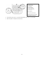
Select program you want to use from the drop down menu. Please refer to below example pictures for M3 T.
55
M3 GREEN
M3 GREEN Function Key Using Guide
M3 GREEN F1 ~ F9 Function Settings
Two different virtual key output values are available for function keys:
i.
ii.
Standard values (FMode=1, ex. returns 0x76 for F7) and
Customized values (FMode= 0, ex. returns 0x85 for F7).
It can be selected through M3.ini configuration.
To use this feature, download WinCE_Startup. Make sure downloaded file includes 3 files; M3.ini,
M3INIT.exe and StartUp.inf and use the latest version of OS.
There are two ways of configuring M3.ini file:
1.
2.
Configuring in PC
Directly configuring in the device.
Configuring in PC
1. Open M3.ini using notepad.
2. FMode setting is located under [M3GREEN_LEFT_SIDE_KEY]
[M3GREEN_LEFT_SIDE_KEY]
Install=1
FKeyTray=1
FMode=1
LSideDown=6
LSideUp=1
FMode = 1 Function key returns the standard values. Ex. Fn+7 returns 0x76, Fn+8 returns 0x77 etc.
FMode = 0 Function key returns M3 customized values. Ex. Fn+7 returns 0x85, Fn+8 returns 0x86 etc.
Set FMode value as you wish and save the change in M3.ini file.
3. Connect the device to PC via ActiveSync.
4. Copy all three files (M3.ini, M3INIT.exe and StartUp.inf) to [My Computer] -> [Mobile Device] -> [Flash Disk]
-> [StartUp] folder.
56
※ If StartUp folder is hidden, change the settings in the folder option.
5. Finally reset the device.
Directly Configuring in the Device
1. Copy the downloaded files as depicted in steps 3 and 4 of ‘Configuring in PC’.
2. To view hidden folders and files, you must uncheck all options in folder option. Then, press 'OK'.
3. Open 'Microsoft WordPad'.
57
4. Open M3.ini file in Microsoft WordPad.
5. Change FMode to 1 or 0 as you wish and save the changes.FMode = 1 -> Function key returns the
standard values. Ex. Fn+7 returns 0x76, Fn+8 returns 0x77 etc.
FMode = 0 -> Function key returns M3 customized values. Ex. Fn+7 returns 0x85, Fn+8 returns 0x86 etc.
58
6. Finally, reset the device.
If FMode is set to ‘0’, the function keys act as defined by M3 and ‘User program 1 to 3’ can be assigned in
‘Buttons’ option.
([Start] -> [Programs] -> [Utility] -> [Buttons])
Function 1 (F+1) refers to User program 1. With this option, you can launch an application by pressing the
function key.
To assign an application to 'Function 1', click 'Function 1' then 'Find' to select application executable file.
These configurations will be lost after hard reset. To keep the settings even after hard reset, we recommend
using MS-Backup.
If FMode is set to ‘1’, the function keys will return following values.
Function Key
Value
Function Key
Value
F1
0x70
F6
0x75
F2
0x71
F7
0x76
F3
0x72
F8
0x77
F4
0x73
F9
0x78
F5
0x74
59
M3 SKY
Floating Keyboard
How do I get a floating SIP keyboard with M3 Sky WM5.0 or 6.1?
[HKEY_CURRENT_USER\ControlPanel\Sip]
"DragStyle"=dword:00000000
This can be coded into the STARTUP.INF file as follows.
RegSetValue=/h dword [HKEY_CURRENT_USER\ControlPanel\SIP]DragStyle: 1
Launching Applications using a Button
How can I set what application is launched when a key is mapped to Application1 or Application2?
You can set Application1 / Application2 in Side Key Settings ([Start]->[Settings]->[Buttons]-> Side Key
settings)
If you want to launch IE with Application1, you can set the value as shown below in registry.
[HKEY_LOCAL_MACHINE\ControlPanel\Keypad\SideKey]
P1Path = /Windows/iexplore.exe
P2Path = Application 2
60
M3 SKY Key Customization
M3 SKY has 8 or 15 customizable keys depending on the keypad.
•
Alphanumeric Keypad - 8 customizable keys
(SKY with phone module)
(SKY without phone module)
61
•
QWERTY Keypad - 15 customizable keys
There are 3 ways to customize the key:
1. Using Windows Mobile GUI
2. Using VisualINI
3. Editing M3.ini
1. Using Windows Mobile GUI
Those keys can be customized as the following.
1. Gently tap the Start button
and from the drop-down
menu, select Settings.
2. In the Settings, select [Buttons].
62
3. Select Side Key Setting.
4. From the Key Setting Window, those 8 (Alphanumeric keypad) or 15 keys (QWERTY keypad) can be
customized.
Note that depending on the PDA option, it may appear differently.
(WM6.1, HSDPA)
(WM5.0, non-GSM)
(QWERTY, WM6.1, HSDPA)
You can assign the following functions to the keys. All keys have the same customization options. Note that
‘Yellow’ and ‘Blue’ keys have ‘VK_F14’ as the default value.
Default
Default value of the keys
VK_ESCAPE
Virtual key for escape.
VK_F13
Virtual key for F13 (user can assign a function to F13)
VK_F14
Virtual key for F14 (F14 is used to scan when ScanEmul is running)
VK_F17
Virtual key for F17 (user can assign a function to F17)
VK_F18
Virtual key for F18 (user can assign a function to F18)
VK_SPACE
Virtual key for space
VK_RETURN
Virtual key for return
SIP ON/OFF
Toggles soft input panel
Application 1
Application 2
Windows
Windows key
Home
Home key
PgUp
Page Up key
End
End key
PgDn
Page Down key
2. Using VisualINI
To use VisualINI, first you need to install it. To install manually, you can click VisualINI.CAB in Driver folder
of Flash Disk or to install automatically after reset, set install value of [VISUALINI_INSTALL] to 1 in m3.ini file.
If VisualINI is installed, you can find StartUp icon at [Start] -> [Settings] -> [Systems] as shown in figure 2.1.
63
Figure 2.1 VisualINI
Figure 2.2 Device setup
Figure 2.3 Side key setting
In the StartUp window, user must set the correct device model (①) then, click ‘OK’ button to confirm it (②).
Before going to the next step, the device must go through soft reset. Then, launch StartUp again to
customize the keys. From figure 2.2, go to SideKey window (③) for key customization. M3 SKY SideKey
customization window is shown in figure 2.3. Check 'Auto Start' if you want to keep the settings even after
hard reset.
3. Using M3.ini
By editing M3.INI file, you can customize the keys as well. M3.INI is located in the StartUp folder in the Flash
Disk of the Device. To edit the file, you may require copying the file to your PC.
If you open M3.INI file, you will find the following section:
////////////////////////////////////////////////////////////////////////////////////////
// M3SKY SideKey
//
// MC7500S, MC7700S, MC7510S
// Function : 0=Default 1=VK_ESCAPE 2=VK_F13 3=VK_F14 4=VK_F16 5=VK_F17 6=SIP on/off
7=VK_RETURN 8=excute application1 9=excute application 10=VK_SPACE
// BLUE/YELLO : 0= Default(VK_F14) 1= VK_ESCAPE 2= VK_F13 3= VK_F16 4= VK_F17 5=
SIP_BUTTON 6=VK_RETURN 7=excute application1 8=excute application 9=VK_SPACE
//
// MC7100S, MC7110S
// Function : 0=Default 1=VK_ESCAPE 2=VK_F13 3=VK_F14 4=VK_F17 5=VK_F18 6=SIP on/off
7=VK_RETURN 8=excute application1 9=excute application 10=VK_SPACE
// BLUE/YELLO : 0=Default(VK_F14) 1= VK_ESCAPE 2= VK_F13 3= VK_F17 4=VK_F18 5=
SIP_BUTTON 6=VK_RETURN 7=excute application1 8=excute application 9=VK_SPACE
//
// MC7101S, MC7501S, MC7701S
// Function : 0=Default 1=VK_ESCAPE 2=VK_F13 3=VK_F14 4=VK_F17 5=VK_F18 6=VK_SPACE 7=VK_RETURN
8=SIP ON/OFF 9=excute application1 10=excute application2 11=Winodws Key 12=Home 13=PgUp 14=End 15=PgDn
16=None
//
// BLUE/YELLOW (only non GSM) : 0=VK_ESCAPE 1=VK_F13 2=VK_F14 3=VK_F17 4=VK_F18 5=VK_SPACE
6=VK_RETURN 7=SIP ON/OFF 8=excute application1 9=excute application2 10=Winodws Key 11=Home 12=PgUp
13=End 14=PgDn 15=None
//
////////////////////////////////////////////////////////////////////////////////////////
// MM3 SideKeyz
// Function : 0:None 1:Default 2:SIP ON/OFF 3:VK_APP1 4:VK_APP2 5:VK_RETURN 6:VK_CONTROL 7:VK_SHIFT
8:VK_ESCAPE 9:Launch Program1 10:Launch Program2 11:Launch Program3
64
//
////////////////////////////////////////////////////////////////////////////////////////
[M3SKY_SIDE_KEY]
Install=0
LEFTDOWN=0
LEFTUP=0
RIGHTDOWN=0
RIGHTUP =0
Blue=0
Yellow=0
SOFT1=0
SOFT2=0
[M3SKY_SIDE_KEY_QWERTY]
Install=0
Only_SendEnd=0
LEFTDOWN=0
LEFTUP=0
RIGHTDOWN=0
RIGHTUP=0
SOFT1=0
SOFT2=0
SEND=0
END=0
SCAN=0
TAB=0
ACTION=0
LEFT=0
RIGHT=0
UP=0
DOWN=0
From the file, change the value of Install to 1 and assign a value according to the function to each button as
you like. Then, copy the modified M3.INI back to the StartUp folder. Customization will be applied after soft
reset of the device.
65
MM3
MM3 Key Customization
Both 55-key version (Left) and 41-key version (Right) of MM3 has 9 customizable keys as shown in the
figure below.
There are 3 ways to customize the keys:
1. Using Windows Mobile GUI
2. Using VisualINI
3. Editing M3.INI
1. Using Windows Mobile GUI
Those keys can be customized as the following (screenshots are taken using 55-key version):
1.
Gently tap the Start button and
from the drop-down menu,
select Settings.
2.
In the Settings select [Buttons]
66
3.
Select Side Key Setting
4.
From the Key Setting Window, those 9 keys can be customized.
You can assign the following functions to the keys. All 9 keys have the same customization options.
None
Disable the button
Default
Default value of the key.
SIP ON/OFF
Toggles Soft Input Panel.
VK_APP1
Virtual key to start application 1.
VK_APP2
Virtual key to start application 2.
VK_RETURN
Virtual key for Return.
VK_CONTROL
Virtual key for Control.
VK_SHIFT
Virtual key for Shift.
VK_ESCAPE
Virtual key for Escape.
Launch Program 1
Launches a program assigned to Program 1.
Launch Program 2
Launches a program assigned to Program 2.
Launch Program 3
Launches a program assigned to Program 3.
Launch Program 4
Launches a program assigned to Program 4.
VK_M3SCAN
Scan key for Telnet Program. Key Value: 0x9C
VK_ACTION
Virtual key for Action.
2. Using VisualINI
To use VisualINI, first you need to install it. To install manually, you can click VisualINI.CAB in Driver folder
of Flash Disk or to install automatically after reset, set install value of [VISUALINI_INSTALL] to 1 in m3.ini file.
If VisualINI is installed, you can find StartUp icon at [Start] -> [Settings] -> [Systems] as shown in figure 2.1.
67
Figure 2.1 VisualINI
Figure 2.2 Device setup
Figure 2.3 Side key setting
In the StartUp window, user must set the correct device model then, click ‘OK’ button to confirm it. Before
going to the next step, the device must go through soft reset. Then, launch StartUp again to customize the
keys.
From figure 2.2, go to MM3SideKey window for key customization. MM3 SideKey customization window is
shown in figure 2.3. Check 'INSTALL' if you want to keep the settings even after hard reset.
Note that from figure 2.3, SHIFT and ESC drop down menus are disabled because the screen shot is taken
using MM3 with 55-key keypad. If 41-key version is used, BACKSPACE and TAB will be disabled and SHIFT
and ESC fields are activated.
FKey Enable is available in B1ST(O/H)V645EN or later version. FKey Enable option is put in to the OS to
make MM3 useful with Telnet programs such as IBM 5250/ IBM 3270 which uses F1 to F24.
This is why VK_M3SCAN is introduced. The default value of SCAN button is F14 which cannot be used in
IBM 5250/ IBM 3270. When SCAN KEY is set to M3SCAN, the scanner will not work with M3 ScanEmul or
ScanTest application.
If FKey is enabled, user can use F1 to F24 on green layer. Please refer to below MM3-5250 keypad.
Note that it has F1 to F24 on green layer on ‘C’ to ‘Z’.
68
3. Editing M3.ini
By editing M3.INI file, you can customize the keys as well. M3.INI is located in the StartUp folder in the Flash
Disk of the Device. To edit the file, you may require copying the file to your PC.
If you open M3.INI file, you will find the following section:
////////////////////////////////////////////////////////////////////////////////////////
// MM3 SideKeys
// Function : 0:None 1:Default 2:SIP ON/OFF 3:VK_APP1 4:VK_APP2 5:VK_RETURN 6:VK_CONTROL
// 7:VK_SHIFT 8:VK_ESCAPE 9:Launch Program1 10:Launch Program2 11:Launch Program3
//
////////////////////////////////////////////////////////////////////////////////////////
[MM3_SIDE_KEY]
Install=0
LEFTSOFT=1
RIGHTSOFT=1
SEND=1
END =1
GREEN=1
YELLOW=1
BACKSPACE=1
TAB=1
ESC=1
SHIFT=1
SCAN=0
EnableFKey=0
From the file, change the value of Install to 1 and assign a value according to the function to each button as
you like. Then, copy the modified M3.INI back to the StartUp folder. Customization will be applied after soft
reset of the device.
69
M3 ORANGE
M3 ORANGE Key Customization
M3 ORANGE provides very flexible key customization. In Alpha-numeric version, all physical buttons except
the power button are customizable subject to the registry change method is used.
However, in general (GUI, M3.INI), only 14 buttons are customizable as shown below.
Customizable keys are: Left Up/Down, Right Up/Down, SEND/END, SOFT1/2, SCAN, Direction Keys, Action
(Alpha-numeric only) and TAB (QWERTY only).
1. GUI Method
[Start] [Settings] [Personal] [Buttons] [Side Key Setting]
70
<Alpha-numeric>
<QWERTY>
All keys shown above can be set to one of the following.
0
Default
Default value of the keys
1
VK_ESCAPE
Virtual key for escape
2
VK_F13
Virtual key for F13
3
VK_F14
Virtual key for F14
4
VK_F17
Virtual key for F17
5
VK_F18
Virtual key for F18
6
VK_SPACE
Virtual key for space
7
VK_RETURN
Virtual key for return
8
SIP ON/OFF
Toggles soft input panel
9
Application 1
User defined application1
10
Application 2
User defined application2
11
Windows
Windows key
12
Home
Home key
13
PgUp
Page Up key
14
End
End key
15
PgDn
Page Down key
16
Disable
Disable the button
17
VK_ACTION
Virtual key for Action
18
. (PERIOD)
Dot or full stop
19
, (COMMA)
Comma
When ‘Only Use Send/End Key’ option is checked in QWERTY device, it will not function as window or OK
on ORANGE layer input mode. In other words,
+(
or
) do not act as
or
.
User can customize the keys as required follow by OK button at the top right corner.
2. M3.INI Method
By editing M3.INI file, you can customize the keys as well. M3.INI is located in the StartUp folder in the Flash
Disk of the Device. To edit the file, you may require copying the file to your PC.
If you open M3.INI file, you will find the following section:
M3Orange
71
Function
: 0=Default 1=VK_ESCAPE 2=VK_F13 3=VK_F14 4=VK_F17 5=VK_F18
6=VK_SPACE 7=VK_RETURN 8=SIP ON/OFF 9=excute application1 10=excute application2
11=Winodws Key 12=Home 13=PgUp 14=End 15=PgDn 16=None 17=.(PERIOD) 18=,(COMMA)
[M3ORANGE_SIDE_KEY]
Install=0
LEFTUP=0
LEFTDOWN=0
RIGHTDOWN=0
RIGHTUP =0
SEND=0
SOFT1=0
SCAN=0
SOFT2=0
END=0
ACTION=0
LEFT=0
UP=0
DOWN=0
RIGHT=0
[M3ORANGE_SIDE_KEY_QWERTY]
Install=0
LEFTUP=0
LEFTDOWN=0
RIGHTDOWN=0
RIGHTUP=0
SEND=0
SOFT1=0
SCAN=0
SOFT2=0
END=0
LEFT=0
UP=0
DOWN=0
RIGHT=0
TAB=0
Only_SendEnd=0
From the file, change the value of Install to 1 and assign a value according to the function to each button as
you like. Then, copy the modified M3.INI back to the StartUp folder. Customization will be applied after soft
reset of the device.
3. VisualINI Method
To use VisualINI, first you need to install it. To install manually, you can click VisualINI.CAB in Driver folder
of Flash Disk or to install automatically after reset, set install value of [VISUALINI_INSTALL] to 1 in m3.ini file.
If VisualINI is installed, you can find StartUp icon at [Start] [Settings] [Systems] [StartUp]
VisualINI provides the same function as the M3.INI file but with GUI. Hence, user can utilize VisualINI where
directly editing M3.INI is not possible.
Make sure INSTALL checkbox is checked to make the modification affected.
4. Registry Change
Under registry path: HKEY_LOCAL_MACHINE\ControlPanel\Keypad\Numeric or QWERTY, user will
find all button keys and values. Sample is shown below.
72
User can change the value of each key from 0 to 18 as required.
How to figure out the each Virtual Key value in Window Mobile?
Please download KeyMonitor program and place into the device.
When any key pressed, each key value will be shown up as up/down for each purpose.
With this key value you need to develop the wedge program(key value transformed) for your goal.
M3 T
Key Setting
i.
How to disable the Numbers / Characters Switch key.
In M3 T, F2 functions to switch between numbers and characters.
Follow below steps to disable F2 function.
Move to StartSettingsControl PanelKeypad option.
Set function assignment for F2 to.
73
ii.
How to use F5 key instead of F4 key?
Please modify the registry value as below.
dword [HKEY_LOCAL_MACHINE\System\MobileCompia\KeyPad\F4] Enable: 1
dword [HKEY_LOCAL_MACHINE\System\MobileCompia\KeyPad\F4] Flags: 0
dword [HKEY_LOCAL_MACHINE\System\MobileCompia\KeyPad\F4] VKey: 116
Furthermore other keys are available to switch mapping by referring to below link path.
http://help.adobe.com/en_US/AS2LCR/Flash_10.0/help.html?content=00000520.html,
key code of F5 is 116. Therefore, I have set F4 to 116 and it worked
iii.
How to figure out the each Virtual Key value?
Please download KeyMonitor program and place into the device.
When any key pressed, each key value will be shown up as up/down for each purpose.
With this key value you need to develop the wedge program(key value transformed) for your goal.
M3 SMART (WM6.5)
M3 SMART (WM6.5) Key Customization
M3 SMART with Windows Mobile 6.5 provides 9 customizable keys as shown below.
74
1. GUI Method
[Start] [Settings] [Personal] [Buttons] [Side Key Setting]
All keys shown above can be set to one of the following.
0
Default
Default value of the keys
1
VK_ESCAPE
Virtual key for escape
2
VK_F13
Virtual key for F13
3
VK_F14
Virtual key for F14
4
VK_F17
Virtual key for F17
75
5
VK_F18
Virtual key for F18
6
VK_SPACE
Virtual key for space
7
VK_RETURN
Virtual key for return
8
SIP ON/OFF
Toggles soft input panel
9
Application 1
User defined application1
10
Application 2
User defined application2
11
Windows
Windows key
12
Home
Home key
13
PgUp
Page Up key
14
End
End key
15
PgDn
Page Down key
16
VK_ACTION
Virtual key for Action
17
None
Disable the button
When ‘Only Use Send/End Key’ option is checked, SEND and END field is disabled and not customizable.
2. Mapping Applications
User can launch user defined application by pressing a button if it is set correctly. User can define 2
applications as shown in above table: Application 1 and Application 2.
The application must be in .exe file format and it can be set by setting a correct path in registry.
Path
Key
Value
: HKEY_LOCAL_MACHINE\ControlPanel\Keypad\MultiFunc
: P1Path (for application 1)
: P2Path (for application 2)
: {.exe file location}
Example of assigning ScanEmul to Application 1 using StartUp.inf is shown below.
RegSetValue=/s string [HKEY_LOCAL_MACHINE\ControlPanel\Keypad\MultiFunc] P1Path :
“\Flash Disk\Scanner\ScanEmul.exe”
3. M3.INI Method
By editing M3.INI file, you can customize the keys as well. M3.INI is located in the StartUp folder in the Flash
Disk of the Device. To edit the file, you may require copying the file to your PC.
If you open M3.INI file, you will find the following section:
//
//
//
//
//
//
M3SMART SideKey
Function : 0=Default 1=VK_ESCAPE 2=VK_F13 3=VK_F14 4=VK_F17 5=VK_F18
6=VK_SPACE 7=VK_RETURN 8=SIP ON/OFF 9=excute application1
10=excute application2 11=Winodws Key 12=Home 13=PgUp 14=End 15=PgDn
16=VK_ACTION 17=None
F1~F10key is the expansion key.
[M3SMART_SIDE_KEY]
Install=1
OnlySendEndFunc=1
VolumeUpKey=0
VolumeDownKey=0
//F1Key=0
//F2Key=0
//F3Key=0
//F4Key=0
//F5Key=0
76
RightDownKey=7
SideUpKey=3
SendKey=0
Soft1Key=0
ScanKey=0
Soft2Key=0
EndKey=0
TabKey=0
SpaceKey=0
BkspKey=0
EnterKey=0
LeftKey=0
UpKey=0
RightKey=0
DownKey=0
WindowKey=0
OKKey=0
ShiftKey=0
LockKey=0
//F6Key=0
//F7Key=0
//F8Key=0
//F9Key=0
//F10Key=0
From the file, change the value of Install to 1 and assign a value according to the function to each button as
you like. Then, copy the modified M3.INI back to the StartUp folder. Customization will be applied after soft
reset of the device.
To assign functions or applications to F keys, uncomment the entry in M3.ini.
i.e. remove // at the front of the entry.
4. VisualINI Method
To use VisualINI, first you need to install it. To install manually, you can click VisualINI.CAB in Driver folder
of Flash Disk or to install automatically after reset, set install value of [VISUALINI_INSTALL] to 1 in m3.ini file.
If VisualINI is installed, you can find StartUp icon at [Start] [Settings] [Systems] [StartUp]
VisualINI provides the same function as the M3.INI file but with GUI. Hence, user can utilize VisualINI where
directly editing M3.INI is not possible.
Make sure INSTALL checkbox is checked to make the modification affected.
5. Registry Change
Under registry path: HKEY_LOCAL_MACHINE\ControlPanel\Keypad\MultiFunc, user will find all
button keys and values. Sample is shown below.
77
User can change the value of each key from 0 to 17 as required.
78
8.
OS
Common
OS naming rule
Please refer to below description of OS naming rule (SKY basis).
The three numbers in red rectangle differentiate the device between Samsung WLAN and Summit WLAN.
Between them, the OS IS NOT COMPATIBLE each other so please make sure your WLAN type matches
with OS that you are going to update.
OS Update via One-click Update
M3 Models Support One-click OS update
Please refer to below table for available PDA and OS versions.
Brand
Model
Board
Summit
MC-7100S
Samsung
M3 SKY
Summit
MC-7500S/7700S
Samsung
MM3
MC-8000S
Summit
Please check the OS version by following below route.
M3 SKY :
Start\Settings\System\Device Info\System
MM3 :
Start\Settings\System\Device Info\System
79
OS
OS Version
WM6.1
All
WM5.0
Not Supported
WM6.1
718 or later
WM5.0
N/A
WM6.1
All
WM5.0
Not Supported
WM6.1
723 or later
WM5.0
N/A
WM 6.1
645 or later
SD Memory Support
Maximum supported SD memory size on M3 PDAs
The maximum size of supported SD card depends on the operating system NOT on the hardware. Please
see the below list.
Brand
M3 RED
M3 GREEN
M3 T, M3 POS
M3 SMART CE
M3 SKY
M3 SKY, MM3
M3 ORANGE, M3 SMART WM
OS
Windows CE 4.2
Windows CE 5.0
Windows CE 5.0
Windows CE 6.0
Windows Mobile 5.0
Windows Mobile 6.1
Windows Mobile 6.5
Max. SD size
2 GB
4 GB
32 GB
32 GB
2 GB
32 GB
32 GB
The recommended SD card brands are SanDISK and Transcend. Other Cards are likely to work. However,
these need to be tested to ensure they meet user requirements.
Note that since the SD memory size is limited by the OS, it will only support 2GB or less when updating OS
using SD card(Only M3 Smart can use up to 32GB for OS update). Also, M3 RED does not support OS
update via SD.
80
M3 RED / M3 GREEN
OS Update via Mini SD Card
CAUTION
Use fully charged battery or AC power while OS update process.
Every information or configurations will be removed after OS update.
Required files for OS update can be downloaded from support webpage.
1. Unzip downloaded file. It should contain .DI file. Ex) TBMCAC212_MCST274EN.DI
2. Copy the file to root folder of Mini SD card.
3. Turn off the device by pressing the reset button for approximately 5 seconds.
4. Insert the Mini SD card into the slot.
5. Press the power button and hold. While the power button is kept pressed, please press the reset
button briefly.
6. On the screen the message, saying “Reading Image from Card”, will be displayed on the screen.
OS install is completed by resetting when the message “Image Upgrade Complete!” is displayed on
the screen.
OS update will remove the previous Flash Disk files. To copy the flash disk files back to the PDA, you can
either use SD card or ActiveSync (via USB).
81
OS Update via USB Downloader
CAUTION
Use fully charged battery or AC power while OS update process.
Every information or configurations will be removed after OS update.
I. Installation
1. Download the USB_Downloader and OS update files to your PC.
It can be downloaded from the support webpage .
2. Turn off the device by pressing the reset button for approximately 4 seconds.
Remember, with hard reset you will lose all your data except the one in flash disk.
3. Press the power button and hold. While the power button is kept pressed, please press the reset
button briefly.
4. At this moment you should be able to see ‘Waiting From USB… ’ message on M3 screen.
5. Place PDA on the cradle (connected to PC) or directly connect to PC via USB cable.
6. ‘Found New Hardware’ message will be displayed on your PC.
7. If the device is connected to the PC for the first time, Microsoft windows will start New Hardware
Wizard automatically. From the options, choose “No, not this time”, then click “Next>” to proceed.
82
*If this is not the first time, please go to Step 11.
8. Choose “Install from a list or specific location (Advanced)” option then proceed.
9. Check “Include this location in the search:” option then, specify the location of the folder which
contains the driver files: bulkusb.sys, bulkusb.inf.
83
Usually those driver files are included in 4.0.1 folder.
10. When the warning window appears, click “Continue Anyway”.
84
Then, click 'Finish' to complete driver installation.
11. Run MCUSBDown.exe in 4.0.1 folder. Click 'Run' when the warning appears.
85
From Image Loader Ver 4.0.1, click 'Open' then select the OS image.
NOTE: If the downloaded OS file only contains .DI file, change the extension of the file
to .PAK
86
12. Click 'Download' to start updating OS.
13. When the Status is Complete, click 'Exit' to complete OS writing.
87
14. When the new OS image is successfully written, it will show "Image Upgrade Complete!" on the
PDA's screen.
Then, reset the device to finish OS update procedure.
OS update will remove the previous Flash Disk files. To copy the flash disk files back to the PDA, you can
either use SD card or ActiveSync (via USB).
88
M3 SKY / MM3
OS Update via (Mini) SD Card
CAUTION
Use fully charged battery or AC power while OS update process.
Every information or configurations will be removed after OS update.
Check first whether the WLAN module type is Summit or Samsung, or wrong OS update may cause severe
damage to device leading to RMA process.
Required files for OS update can be downloaded from support webpage.
1. Formatting MiniSD - please format MiniSD card on PC in FAT (recommended) or FAT32 format.
2. Please copy OS image file (must in name FLASH.DIO), Boot image file (BOOT.NB0) and
SPLASH.BMP to SD card and then insert it into the device.
Note that the SD Card for each device has different dimensions. SKY uses MiniSD and SD for MM3.
3. The device should be turned off first. The device power can be turned off by pressing the
‘Power button’ for 10 seconds.
4. Press the right arrow button and keep pressing. Press the power button briefly to enter Boot menu.
5. Select [1. Update] Press return button.
6. Select [1. SD Update] -> [2. BOOT Update]
7. Turn off the device by pressing the power button for 10 seconds. Then re-enter the boot menu.
89
8. Select [2. Format All] and press return button.
'Format all partitions Confirm it' message will be displayed.
9. Select [1. Yes]
'Format completed Update boot and OS' message will be displayed.
Then, select [0. BACK] to enter Main MBoot MENU.
10. From the main boot menu, select [1. Update] -> [1. SD Update] -> [3. SPLASH Update].
SPLASH update will update the image that is displayed when booting.
To use your own image, you should have 240 x 320 pixel 24 bit bitmap file and save it as
SPLASH.bmp.
After successful update, return to the update menu.
11. Select [2. BOOT Update] N.B. We strongly recommend updating BOOT prior to OS update. 'BOOT.
NB0 Write done' message will be displayed.
Then, turn off the terminal again and re-enter the boot menu.
12. Select [1. Update] -> [1. SD Update] -> [1. OS Update] from the update menu.
'Writing done. Reset Device!!' message will be displayed.
Then, finish OS update by resetting the device.
[Format All] process will remove the previous Flash Disk files. To copy the flash disk files back to the PDA,
you can either use SD card or ActiveSync (via USB).
90
OS Update via One-click Update
CAUTION
Use fully charged battery or AC power while OS update process.
Every information or configurations will be removed after OS update.
Check first whether the WLAN module type is Summit or Samsung, or wrong OS update may cause severe
damage to device leading to RMA process.
Required files for OS update can be downloaded from Support webpage.
Downloaded zip file will contain two folders: Oneclick_Update and SD_USB_Update.
To use one-click update, simply copy the mpk file to the flash disk of the PDA and run it.
Then, it will automatically update splash, boot and OS, and reset.
In the case where the mpk file is not available, you can make mpk file using MakeMPK.exe.
1. Run MakeMPK.exe on your PC and select correct OS image, boot and splash file.
※ Auto File Name Set is checked - When selected OS Image folder that has the Boot and Splash file,
the folder path will be set automatically. And Target Folder will also automatically set the path.
2. Select the Target Folder and Insert the Target Name. And press the Start button, a new file will be
created on the Target Folder path.
3. Please store the created file on the SD card and insert the SD card in the device. Please run the file
(.MPK) to proceed. OS update.
OS update will remove the previous Flash Disk files. To copy the flash disk files back to the PDA, you can
either use SD card or ActiveSync (via USB).
91
OS Update via USB Downloader
CAUTION
Use fully charged battery or AC power while OS update process.
Every information or configurations will be removed after OS update.
Check first whether the WLAN module type is Summit or Samsung, or wrong OS update may cause severe
damage to device leading to RMA process.
I. Installation
1. Download the USB_Downloader and OS update files to your PC.
It can be downloaded from the support webpage .
2. Copy the rndismpy.sys and usb8023y.sys files (in USB_Downloader-> USB drive) to on your PC in
this path (Windows\System32\Drivers).
3. Turn off the device (The device power will be turned off by pressing the ‘Power button’ for ten
seconds.)
4. Press the right arrow key then briefly press Power button. [MBOOT MENU] will be displayed.
5. Please select [Update] -> [TFTP Update] then select the requested updates.
6. On the screen ‘Waiting for USB connect…’ will be displayed.
7. Please connect the device to PC via USB cable.
8. Now the PC will detect NEW hardware.
9. For install driver you have to browse the Folder in USB_Downloader -> USB Driver. The driver is
called ‘RNDIS_PXA270.inf’.
92
10. Turn off the device (The device power can be turned off by pressing the ‘Power button’ for ten
seconds.).
11. Press the right arrow key together with Power button. [MBOOT MENU] will be displayed.
12. Please select Update -> TFTP Update then select the requested updates.
13. On the screen ‘Waiting for USB connect…’ will be displayed.
14. Please connect the device to PC via USB cable.
15. On your PC Network Connections -> MobileCompia Network -> Properties.
16. Internet Protocol (TCP/IP) -> Properties.
17. Set IP: 10.0.0.5 / Subnet Mask: 255.0.0.0
93
II. Upload OS
1. Run TFTPClientV1.4.exe in USB_Downloader.
2. Update OS in the order Splash -> Boot -> OS image.
3. The device should be turned off first. Press the right arrow button and keep pressing. Press the
power button briefly. The [MBOOT MENU] will be displayed.
94
4. From boot menu, select [Update] -> [TFTP Update].
5. The upload is ready to proceed, when you see the message 'Update process is ready' on the TFTP
Client.
6. When you see above message, press 'Start' to begin the upload process.
CAUTION - Do not power off the device or remove Ethernet cable during this process.
OS update will remove the previous Flash Disk files. To copy the flash disk files back to the PDA, you can
either use SD card or ActiveSync (via USB).
95
OS Update via USB in Windows 7 (M3 SKY)
CAUTION
Use fully charged battery or AC power while OS update process.
Every information or configurations will be removed after OS update.
Check first whether the WLAN module type is Summit or Samsung, or wrong OS update may cause severe
damage to device leading to RMA process.
This method can only be used while you are using Windows 7. Because of Firewall on Windows 7, USB
update method for Windows XP cannot be used to update OS
Also M3 SKY (Summit model only) must have installed compatible boot version to use this method.
-
MC-7100 series must have boot version installed higher than MBoot V 4.1.5
-
MC-7500 series must have boot version installed higher than MBoot V 9.0.8
You can check this information either from MBoot menu or from [Start] [Setting] [System] [Device
Info].
Download M3 Black Driver from this Link. (Contents: M3BlackUSB.inf, M3BlackUSB.sys, USBLoad.exe)
A.
Get into Mboot Menu (Turn off the device first, while the device has turned off, press right directional
key and tap power button.)
B.
Select [1. Update] [2. USB Update] [1.Windows 7]
C. Place device on cradle and connect to PC via USB cable.
D. Your PC will show following message ‘Installing device driver software’
E.
Move on to following paths Start->Device and Printer->Device manager and choose unknown
device from lists below, right click on it and choose ‘Update Driver’.
F.
Once you got pop up window, choose ‘Browse my computer for driver software.’
G. Choose ‘SKY_Win7_Downloader’ folder which contains M3BlackUSB.inf, M3BlackUSB.sys.
96
H. Once the installation is successfully done, you will be able to see, ‘The best driver software for
your device is already installed’ message.
I.
Run USBLoad.exe file which was downloaded with other files that you have used to install driver for
device.
97
J.
Click ‘Open’ and find Boot file manually, at this stage it could be handy for you to choose filename
extension as ‘*.nB0’ to make sure you are choosing right file to be installed.
K.
Once you have chosen the right file to be installed, click ‘Download’ on right hand side to process
installation.
L.
Once you see ‘Write Done Reset device !!’ message from the PC USBLoader, press ‘0’ from the
device to proceed reset.
M. Turn off the device and remove it from the cradle, once you get into Mboot Menu, place the device
at cradle again, you will be able to see ‘USB Connected’ message from the device screen.
[1. Update] [2. USB Update] [1. Windows 7]
N. Click ‘Open’ on ‘USBLoad.exe’.
98
O. Choose OS Image file (Choose filename extension as *.DIO)
P.
As above, press ‘Download’ and wait until you get the message. ‘All files Download Complete.’
Q. Proceed reset from the device by press ‘0.Reset’, once you see the message ‘Write Done Reset
device !!’
99
M3 T
OS Update via Micro SD Card
CAUTION
Use fully charged battery or AC power while OS update process.
Every information or configurations will be removed after OS update.
Required files for OS update can be downloaded from support webpage.
1. Unzip downloaded file. It should contain 4 files: EBOOT.nb0, logo.bmp, MOBM_bc.nb0 and NK.bin.
2. Copy the file to root folder of Micro SD card.
3. Turn off the device by pressing the reset button for approximately 5 seconds.
4. Insert the Micro SD card into the slot. You can see the slot when you detach the battery.
5. Press RESET button while holding the power button. When the display turns on, release the power
button and push it again to launch boot menu.
100
6. From the boot menu, select [3: SD Update]. It will start updating automatically. When 'Reset...'
message appears on the screen, reset the device.
OS update will remove the previous Flash Disk files. To copy the flash disk files back to the PDA, you can
either use SD card or ActiveSync (via USB).
101
OS Update via USB Downloader
CAUTION
Use fully charged battery or AC power while OS update process.
Every information or configurations will be removed after OS update.
I. Installation
1. Download the USB_Downloader and OS update files to your PC.
It can be downloaded from the support webpage .
2. Turn off the device by pressing the reset button for approximately 4 seconds.
Remember, with hard reset you will lose all your data except the one in flash disk.
3. Press RESET button while holding the power button. When the display turns on, release the power
button and push it again to launch boot menu.
4.
From the boot menu, choose “2: USB Update”. ‘Connect USB Cable… ’ message will appear at the
bottom left corner of the LCD.
5. Place M3 T on the cradle and connect to a PC via USB cable.
6. ‘Found New Hardware’ message will be displayed on your PC.
7. If the device is connected to the PC for the first time, Microsoft windows will start New Hardware
Wizard automatically. From the options, choose “No, not this time”, then click “Next>” to proceed.
102
*If this is not the first time, please go to Step 11.
8. Choose “Install from a list or specific location (Advanced)” option then proceed.
9. Check “Include this location in the search:” option then, specify the location of the folder which
contains the driver files: M3BlackUSB.sys, M3Black.inf.
103
10. When the warning window appears, click “Continue Anyway”.
Then, click 'Finish' to complete driver installation.
104
11. Run USBLoad_V0.22.exe then click 'Open'.
Change 'File of type' to (*.bin) then open NK.bin file.
105
12. Click 'Download' to start updating OS. Below image indicates OS update is in progress.
'Downloading***' message will appear on the LCD when the OS is being updated.
13. When OS update is completed, 'Reset' message will appear on the LCD. Then reset the device by
briefly pressing the reset button on the device.
OS update will remove the previous Flash Disk files. To copy the flash disk files back to the PDA, you can
either use SD card or ActiveSync (via USB).
106
M3 ORANGE
OS Update via MicroSD Card
CAUTION
Use fully charged battery or AC power while OS update process.
I. Installation
1. 1. When unzip the download OS file, there are two files which are EBOOT.nb0, bootloader file, and
FLASH.bin, OS image file. Check the boot and OS version and copy file which needs to be updated
between them or both to root folder of microSD card. Then insert the SD card to the device.
Caution: When SD card is used for OS update, SDHC is not supported and the capacity should be
less than 2G.
2. Turn off the device by pressing the power button for approximately 10 seconds.
Then, while pressing the right arrow button, press power button to enter the boot menu.
<PBOOT Menu Example>
3. Select SD update to update OS. When OS update is complete, reset the device.
107
OS Update via USB Downloader
CAUTION
OS update via USB Downloader is NOT supported in Vista or Windows7.
Driver installation only needs to be done for the first time.
I. Installation
1.
Download the USB_Downloader and OS update files to your PC.
It can be downloaded from the support webpage.
2.
Turn off the device by pressing the power button for approximately 10 seconds.
Then, while pressing the right arrow button, press power button to enter boot menu.
<PBOOT Menu Example>
3.
From the boot menu, press ‘1’ to select USB Update. Connect USB Cable... message will display
on the screen.
4.
Place M3 ORANGE on the cradle and connect to a PC via USB cable. ‘Found New Hardware’
message will be displayed on your PC.
108
5.
If the device is connected to the PC for the first time, Microsoft windows will start New Hardware
Wizard automatically. From the options, choose “No, not this time”, then click “Next>” to proceed.
6.
Choose “Install from a list or specific location (Advanced)” option then proceed.
7.
Check “Include this location in the search:” option then, specify the location of the folder which
contains the driver files: M3BlackUSB.sys, M3Black.inf.
109
8.
When the warning window appears, click “Continue Anyway”.
9.
Then, click 'Finish' to complete driver installation.
110
10. When it is ready, run USBLoad.exe. Click on Open button as indicated on the image to load
necessary files.
Please load files in the following order:
a. EBOOT.nb0
b. FLASH.bin
11. When all files are loaded, click Download to start OS update.
12. Reset the device when OS update is complete.
111
M3 SMART WM
OS Update via MicroSD card
NOTE
1.
When MicroSD card is used for OS update.
2.
This manual assumes updating both BOOT and OS using IMAGES.BIN.
3.
Please make sure your device type whether 2G or 3G type.
-
Ex) OS ver. : C3STH6150EN(‘H’ means HSPA, 3G type)
Product No. : UA10HGDNKLxxxxx
-
Ex) OS ver. : C3STG6147EN(‘G’ means GSM, 2G type)
Product No. : UA10GPDNLG41897
CAUTION
Use fully charged battery or AC power while OS update process.
1. To update the OS, user can choose update files to suit their requirements.
BOOT.BIN
FLASH.BIN
IMAGES.BIN
IPL.BIN
- used to update BOOT only
- used to update FLASH (OS) only
- used to update BOOT and OS (Recommended)
- used to update boot image (splash image)
Copy IMAGES.BIN to root folder of MicroSD then, insert the micro SD card to the device.
2. Turn off the device by pressing the power button for approximately 10 seconds.
Then, while pressing the right arrow button, press power button to enter the boot menu.
112
[BOOT MENU 1.0.2]
1) SD Download
2) USB Download
3) Clean Boot
4) Factory Reset
5) Device ID(UUID)
6) Debug Serial:[NO]
7) ALL Format
Select Number
0) Exit:Launch OS image
SAMSUNG-S5PC100 833MHz
RAM 256MB / ROM 1GB
3. From the boot menu, press ‘1’ to enter SD Update Mode. Then, press ‘3’ to start update.
4. When OS update is completed, reset the device.
113
OS Update via USB Downloader
NOTE
Driver installation only needs to be done for the first time.
I. Driver Installation
1. Download all necessary files to your PC.
① OS file.
② USB Update tool: M3SMART_USBDown.zip
③ USB Driver if necessary: M3SMART_Driver.zip
2. Turn off the device by pressing the power button for approximately 10 seconds.
Then, while pressing the right arrow button, press power button to enter boot menu.
[BOOT MENU 1.0.2]
1) SD Download
2) USB Download
3) Clean Boot
4) Factory Reset
5) Device ID(UUID)
6) Debug Serial:[NO]
7) ALL Format
Select Number
0) Exit:Launch OS image
SAMSUNG-S5PC100 833MHz
RAM 256MB / ROM 1GB
3. From the boot menu, press ‘2’ to enter USB Download Mode. Then, press ‘1’ to prepare the PDA for
USB OS update.
[ USB Download Mode ]
When it displays USB Download Ready, connect the PDA to
the PC.
USB Download Ready..
Please Send Image File
0) Power Off
4. Place M3 SMART on the cradle and connect to a PC via USB cable. ‘Found New Hardware’
message will be displayed on your PC and will automatically install required driver.
If the driver is installed properly, please go to step 11, otherwise proceed to step 5.
114
5. If the driver is not installed properly, the driver must be installed manually.
Please open Device Manager. (Control Panel > Hardware and Sound > Devices and Printers >
Device Manager).
6. Double click on SEC S5PC100X Test B/D to open the properties and click on Update Driver…
115
7. Click on Browse my computer for driver software
8. Then, select the folder where the driver files are located by click on Browse…
9. When a warning window pops up, click on Install this driver software anyway.
116
Then, it will start installing driver software.
10. Close the window after the driver installation is successfully done.
117
11. Launch USBDown.exe to start OS update.
12. Select ‘All Image’ and click on Open to select Images.bin, OS file.
13. When the correct OS file is selected, click start to proceed.
14. When OS update is complete, PDA will display complete message on the screen. Then press ‘0’ to
launch OS image.
118
9.
RFID
Common
RFID Frequencies
RFID is divided into three categories depending on the frequency used.
RFID Type
Frequency Band
LFID (Low Frequency Identification)
120~140 kHz
HFID (High Frequency Identification)
13.56 MHz
UHFID (Ultra High Frequency Identification)
868 ~ 956 MHz
Supported Tags
There are 3 types of RFID that M3 device supports: Ultra High frequency, High frequency and Low frequency.
Transfer command
Serial Number
Manufacturer
Tag
Read/Write operation
1. High frequency supported Tag
Comments
ISO 14443 A
MIFARE® Standard
NXP
MIFARE® 4k
NXP
MIFARE® Ultralight
NXP
MIFARE® ProX
NXP
MIFARE® DESFire
NXP
-
MIFARE® Mini
NXP
SLE66CLX320P
Infineon
-
Encryption not included
SLE 55R04 / 08
Infineon
-
Encryption included
Smart MX
NXP
-
Jewel
Innovision
Topaz
Innovision
SLE6666CL 160S
Infineon
-
SR176
STM
SLIX 4K
STM
ASK GTML2 ISO
ASK
-
ASK GTML
ASK
-
Sharp B
Sharp
-
TOSMART P0032/64
Toshiba
-
ISO 14443 B
119
Extended setup needed
Dual Interface
ISO 14443 A compliant
Various
-
ISO 14443 B compliant
Various
-
EM 4135
EM
ICode® SLI
NXP
LRI12
STM
LRI64
STM
LRI128
STM
LRI2k
STM
SRF55VxxP
Infineon
SRF55VxxS
Infineon
ISO 15693
With 10% modulation index
Better performance with 10%
modulation index
Encryption included
TM
HF-I Std
TI
TM
HF-I Pro
TI
-
-
Only in addressed mode
KSW
-
Temperature logging
ICode®
NXP
ICode® EPC
NXP
ICode® UID
NXP
Tag-it
Tag-it
TempSense
ICode
2. Low frequency supported tag.
Tag
Serial
Number
Read
block
Write
block
Properties
EM4x02
-
-
5 bytes R/O
EM4x50
32 x 4 bytes R/W, password
HITAG1
64 x 4 bytes R/W
HITAG S
1, 8 or 64 x 4 bytes R/W
HITAG2
7 x 4 bytes R/W, password
EM4x05
(ISO-FDXB)
-
-
8 bytes R/O
Q5
8 x 4 R/W, password
TI-RFID SYSTEMS
64 Bit R/O
-
-
8 bytes R/O
TI-RFID SYSTEMS
64 Bit R/W
8 bytes R/W
TI-RFID SYSTEMS
1088 Bit Multipage
17 x 8 bytes R/W
120
3. Ultra High Frequency supported compliant.
TAG Type – Tag Antenna Width
UHF C1G2 EPC
860-960MHz
- 2 Cm
UHF C1G2 EPC
860-960MHz
- 3 Cm
UHF C1G2 EPC
860-960MHz
- 8.5 Cm
UHF C1G2 EPC
860-960MHz
- 9 Cm
UHF C1G2 EPC
860-960MHz
- Card Type TAG
*Reading distance may vary depends on UHF type (FCC&ETSI).
121
10.
SERIAL COMMUNICATION
Common
COM port description
What are the Com Ports that are used on the M3 series?
Each COM port is differently used depending on devices. Please refer to below table for the COM Port
description.
COM
0
1
2
3
M3 RED
Internet
-
M3 GREEN
Vehicle Cradle Serial
Internet
-
M3 T
USB
GPS
M3 POS
Serial1
RFID
4
Bluetooth
5
6
7
8
9
MOC1
Phone
Scan / Serial
BT / IrDA (Shared)
-
Bluetooth
-
Phone
Scanner
Bluetooth
IrDA / Serial (Shared)
Bluetooth
-
Serial
Scanner
Serial2
Serial3
BT (SS1)
-
ICCard
Bluetooth
Scanner
Printer
Phone
Serial w/ PW
-
COM
0
1
2
M3 SKY, MM3
Vehicle Cradle Serial
Phone
GPS
M3 ORANGE
Vehicle Cradle Serial
GPS
M3 SMART CE
Phone
3
-
-
GPS/DEBUG
-
4
IrDA
-
Scanner
-
M3 SMART WM
Phone
GPS / DEBUG / Serial
5
-
-
-
-
6
Scanner
Scanner
Bluetooth
Scanner
7
BT (MS)
USB
-
USB
8
Serial
Serial
Bluetooth
-
9
MOC1
BT (SS1)
RFID
BT (MS, SS1)
RFID
-
BT (MS, SS1)
-
122
Supported Baud Rates
Below table summarizes the supported baud rate range and test method for each PDA models.
Model
OS
Method
COM Port
Min (Bd)
Max (Bd)
M3 RED
CE 4.2
Snap-on
COM 6
1200
115200
M3 GREEN
CE 5.0
Snap-on
COM 8
300
115200
M3 SKY
WM 6.1
Snap-on
COM 8
300
115200
M3 ORANGE
WM 6.5
Serial Cradle
COM 8
1200
115200
M3 T
CE5.0
Serial Cradle
COM 8
1200
115200
MM3
WM 6.1
Serial Cradle
COM 8
300
115200
M3 SMART CE
CE 6.0
Not Supported
-
-
-
M3 SMART WM
WM 6.5
Serial Cradle
COM 2
300
115200
M3 POS
CE 5.0
Cradle
COM 2
300
115200
Note that this result is to provide a brief idea of the supported baud rate range. Also, it has been tested from
300 baud to 115200 baud only. Therefore, the minimum and the maximum value may differ to above results.
123
11.
PHONE (GPRS)
Common
Difference between EDGE and 3G
rd
Difference between EDGE (Enhanced Data rates for GSM Evolution) and 3G (3 Generation) is summarized
in below table.
Please note that speed figures shown above is maximum speed you can get, not definite speed that you can
get from M3 products.
Refer to below table for Up/Download rate of EDGE and HSDPA.
Technology
Download Rate
(bit/s)
Upload Rate
(bit/s)
EDGE
236.8 kbit/s
236.8 kbit/s
HSDPA
13.98 Mbit/s
5.760 Mbit/s
Note: Please note that above figures are standard only, not actual rate of M3 products.
For more information, please refer to the linked explanation.
http://www.differencebetween.net/technology/difference-between-edge-and-3g/
124
M3 GREEN
Dialing Window
How can I disable the Dialing window?
When the WLAN is re-connected while using the phone and the WLAN at the same time, you can show the
dialing window as below picture.
There are two methods to disable the dialing window.
1. Delete the MC folder or change the name of it in Flash Disk
Enter [My Device]->[Flash Disk].
Rename or delete the MC folder.
2. Enable "Use LAN"
Another method to disable the dialing window is as below;
Follow these steps : [Start]->[Settings]->[ControlPanel]->[Internet Options]
125
Check the Use LAN(no autodial).
126
Windows Mobile (M3 SKY, MM3, M3 ORANGE, M3 SMART WM)
RIL Log
How to obtain a RIL Log
This document guides the user to obtain a RIL log for WWAN (GSM, HSDPA) modules. There are two ways
in obtaining a RIL log file.
- Changing a registry value for 3G HSDPA only
- Using rilgsm.dll for 2G GSM Only
1. Changing Registry Value (For 3G HSDPA Only)
If your device does not have the registry key, DisableDebugFile, use the second method to obtain the RIL log.
i.
Change the following registry value to ‘0’
[HKEY_LOCAL_MACHINE\Software\RIL] DisableDebugFile: 0
User can either use a registry editor or StartUp.inf to edit the value of registry.
For using StartUp.inf to modify the registry value, please refer to M3 FAQ.
An example of a registry editor is shown above.
ii.
After changing the registry value, soft reset the device.
iii.
When PDA boots up, RilDrv.txt file will appear in root directory.
When M3 ask for RIL log, please turn on the PDA and reproduce the issue.
Then, send the copy of RilDrv.txt or RilDbg.log to M3 Mobile Technical Support.
Left: RilDrv.txt file is created in the
root directory when registry changing
method is used.
Right: RilDbg.log file is created in the
root directory when rilgsm.dll is used.
127
2. Using RILGSM.DLL to Obtain RIL Log File (For 2G GSM Only.)
This method requires copying rilgsm.dll to Windows folder. To copy the dll file to Windows folder, the
operating system must be unlocked. Follow below steps.
i.
Copy m3sky7500summmit_rilgsm_debugfile.zip to Flash Disk folder
Download m3sky7500summmit_rilgsm_debugfile.zip file and unzip then copy 5 files(LtkUnlock.exe,
rapienable.exe, multiplx.dll, rilgsm.dll and Rilgsm.exe) to \My Device\Flash Disk.
Run ‘Rilgsm.exe’ then below messages show up.
Please, make a soft-reset.
ii.
When PDA boots up, RilDbg.log file will appear in root directory.
128
GPRS Settings
To use GPRS, must enter required information such as APN (Access point name), username and password
information which is provided by the operator.
There are 4 ways of configuring GPRS connection:
1. Using WM Connections setting wizard (manual configuration)
2. Using WWAN Manager (semi-auto configuration)
3. Using StartUp.inf included in StartUp folder of M3 flash disk files and operator’s .ini file (auto configuration)
4. Using XML (auto configuration)
1. GPRS Configuration using WM Wizard
To configure GPRS connection, follow the steps described below.
1. Click [Start][Settings]
2. Click [Connections]
3. Click ‘Add a new modem connection’ either in ‘My
ISP’ or ‘My Work Network’.
4. Assign a unique name for the connection and
select ‘Cellular Line (GPRS)’ from the drop down
menu. Then, click ‘Next’
5. Enter ‘Access point name’ that is provided by the
operator. Then, click ‘Next’.
6. Enter Username and password that are also
provided by the operator. Then, click ‘Finish’.
129
7. After the GPRS profile is created, you can connect
to the profile in ‘Manage existing connections’ from
(iii).
8. Select one profile. Then, press and hold the stylus
pen on the profile. From the pop-up menu, click
‘connect’ to connect to GPRS.
2. WWAN Manager
To use WWAN Manager, WWAN_Manager.CAB must be installed. There are two ways of installing WWAN
Manager:
1. Click WWAN_Manager.CAB in \Flash Disk \Driver or
[GPRS_INSTALL]
Install=1
InstalFile=\Flash Disk\Driver\WWAN_Manager.CAB
2. Set Install value of [GPRS_INSTALL] to 1 in M3.ini
130
1. Click [Start] [Settings].
2. Click [WWAN Manager] icon from [Connections] window.
3. Select Country / Region.
131
4. Select Operator (Service Provider).
5. Click 'Done' when finished.
If the operator you wish to connect does not appear in operator drop down menu, you can add new operator
through ‘Add New Parameters...’ or if the operator’s details are wrong, you can edit it through ‘Edit Network
Parameters...’
3. GPRS Configuration using StartUp.inf and .ini file provided by the Operator
To configure GPRS by this method, you need to have a copy of .ini file which contains the operator’s details
something similar to:
[Country_Operator]
NUMBER=
IP_ADDRESS=
DNS_pRIMARY=
DNS_SECONDARY=
WINS_PRIMARY=
WINS_SECONDARY=
APN=
USERNAME=
PASSWORD=
CSD_PHONE_NUMBER=
CSD_USER_NAME=
132
CSD_USER_PW=
If you have the .ini file, copy the file to \Flash Disk \Driver. Then, add the following code in the StartUp.inf
which is included in the StartUp folder of M3 flash disk files.
//GPRS Connection
CopyFile=/S "\Flash Disk\Driver\Country.ini" "\Windows\Provider\Country.ini"
sleep=500
RunExe= /S "\Windows\WWAN_Manager.exe" "Country,Country_Operator "
RegSetValue=/s dword
[HKEY_LOCAL_MACHINE\Software\Microsoft\RIL]SetGPRSAuthentication:2
RunExe =/s "\Windows\WWAN_Manager.exe" "1,Country,Country_Operator"
Note: In the code, Country.ini, Country_Operator and Country are arbitrary examples. You should change it
appropriately. In the last line of code, '1' will create the connection profile in My Work Network and '0' will
create the connection profile in My ISP.
For operators included in WWAN Manger, corresponding .ini file is already included in \Windows \Provider
folder. Hence, CopyFile command is not required.
Here is an example code.
//GPRS Connection
CopyFile=/S "\Flash Disk\Driver\Korea(South).ini"
"\Windows\Provider\Korea(South).ini"
sleep=500
RunExe= /S "\Windows\WWAN_Manager.exe" "Korea,Korea(South)_KTF "
RegSetValue=/s dword
[HKEY_LOCAL_MACHINE\Software\Microsoft\RIL]SetGPRSAuthentication:2
RunExe =/s "\Windows\WWAN_Manager.exe" "0,Korea,Korea(South)_KTF"
Finally, open M3.ini file which is also included in StartUp folder of the flash disk files. Then, set install value of
1 of [GPRS_INSTALL].
[GPRS_INSTALL]
Install=1
InstallFile=\Flash Disk\Driver\WWAN_Manager.CAB
Save the changed in StartUp.inf and M3.ini file then copy back to the device followed by reset.
4. Using XML
To use auto configuration using xml, GPRS.xml file is required. Here is an example of GPRS.xml.
Note that you must set [SET_GPRS], [GPRS_INSTALL] should set to 1 in M3.ini
In the XML file, you can set Connection Name, UserName, Password, APN as below.
<wap-provisioningdoc>
<characteristic type="CM_GPRSEntries">
133
<!--Connection Name: Sample-->
<characteristic type="Sample">
<parm name="DestId" value="{436EF144-B4FB-4863-A041-8F905A62C572}"/>
<!--UserName: -->
<parm name="UserName" value="" />
<!--Password: -->
<parm name="Password" value="" />
<!--Domain: -->
<parm name="Domain" value="" />
<characteristic type="DevSpecificCellular">
<parm name="BearerInfoValid" value="1"/>
<parm name="GPRSInfoValid" value="1"/>
<parm name="GPRSInfoProtocolType" value="2"/>
<parm name="GPRSInfoL2ProtocolType" value="ppp"/>
<!--APN: rsit.comcel.com.co -->
<parm name="GPRSInfoAccessPointName" value="rsit.comcel.com.co"/>
<parm name="GPRSInfoAddress" value=""/>
<parm name="GPRSInfoDataCompression" value="1"/>
<parm name="GPRSInfoParameters" value=" "/>
</characteristic>
</characteristic>
</characteristic>
</wap-provisioningdoc>
Copy GPRS.xml file into \Flash Disk\StarUp folder. And set install values of [SET_GPRS] and
[GPRS_INSTALL] to 1 in M3.ini.
[SET_GPRS]
Install= 1
[GPRS_INSTALL]
Install=1
InstallFile=\Flash Disk\Driver\WWAN_Manager.CAB
Save the changes in M3.ini then copy back to the device followed by reset.
134
12.
SCANNER
Common
Remote Desktop Connection
Automatic Disconnection of Remote Desktop Connection
If you are using the RDC (Remote Desktop Connection) on your PDA, you may experience automatic
disconnection of the RDC with the following error message on the screen.
This error message appears because the terminal has been in the idle state for longer than the time limit set
by the server administrator or by network policies as indicated in the message. The time limit is usually set to
10 minutes.
Since the time limit is set by the network system, it will not be solved by any configuration on the PDA. To
prevent this automatic disconnection,
1. You will need to set the time limit longer than 10 minutes on the network system (consult your
network administrator) or
2. Periodically send a packet to the server on your application to avoid going in to the idle state for
longer than 10 minutes. The packet sending period should be less than 10 minutes obviously.
Please alter either the
1) Network system time limit or
2) Your application on your preference.
135
Switching Case of Decoded Character
Scan output type can be configured from ScanEmul option.
Keyboard Msg output is affected by virtual keypad settings. For instance, if the CAP button is pressed in SIP,
the result will be in capital letter.
Clipboard output is not affected by virtual keypad settings.
Note: Default type is keyboard Msg.
Keyboard Msg: Outputs the barcode results one by one (Slower than clipboard type).
Clipboard: Outputs the whole result at once as in 'copy and paste' (faster than the keyboard Msg type).
136
Windows CE (M3 GREEN, M3 T, M3 POS)
Remote Desktop
Scan button doesn't work in Remote Desktop.
If scan button is not working in ScanEmul when using Remote Desktop, check the following lists.
Checking procedure:
1. WLAN must be connected to an AP properly.
2. Check if you can browse a website (Eg: www.google.com).
3. Launch Remote Desktop and configure as below. \Flash Disk\Scanner\ScanEmul.exe
4. Close the option window and enter IP address that you wish to access.
5. Click connect button and enter appropriate ID and PW to connect to remote desktop.
6. Perform scan test after opening notepad or wordpad from remote desktop.
137
Windows Mobile (M3 SKY, MM3, M3 ORANGE, M3 SMART WM)
Hotkey
Can I apply Hotkey irrelevantly to the form?
How to use Hotkey
Register Hotkey on openning scanner: ScanCtrl.RegHotKey(1, m_nHotKey, m_bSyncMode, m_nTimeOut);
Unregister Hotkey on closing scanner: ScanCtrl.UnRegHotKey(1);
Obtaining scanner data
private void OnScanData(object sender, ScannerDataArgs e)
{
if (ScanListView.Items.Count > 7)
ScanListView.Items.Clear();
if (e.ScanData != "")
{
ListViewItem ScanData = new ListViewItem();
ScanData.Text = e.ScanType;
ScanData.SubItems.Add(e.ScanData);
ScanListView.Items.Add(ScanData);
PlaySound("\\windows\\Alarm1.wav", 0, (int)(SND.SND_ASYNC |
SND.SND_FILENAME));
}
}
138
13.
SOFTWARE
Common
Memory Allocation
How is Memory Allocation in M3 PDAs divided by between ROM and RAM?
M3 GREEN 128MB RAM / 256MB ROM
The 128MB RAM is divided up between REAL MEMORY for running applications and NON persistent
Storage Space. This can be adjusted using the M3 Green Memory Slider Bar found in the control panel.
The 256MB ROM is Persistent storage. Approx 64 MB is used to HOLD and LOAD the Operating System.
The remaining 192 MB is available under the /Flash disk Folder as PERSISTENT Storage.
M3 SKY, MM3 128MB RAM / 256MB ROM
The 128MB RAM is REAL program memory used for running applications. The 256MB ROM is divided
between storage space, persistent storage and OS Files. The breakup is as follows
OS files - WM5.0: 40MB
WM6.1: 64MB
Storage - WM5.0: 80MB
WM6.1: 44MB
Flash Disk = ROM size – (OS+Storage) = 140MB
All STORAGE and FLASH DISK is PERSISTENT. The only difference is a CLEAN BOOT will ERASE
Storage but leave FLASH DISK intact.
M3 ORANGE 256MB RAM / 1GB ROM
ROM (1GB) = BOOT(1MB) + Kernel image(67MB) + Kernel filesystem(60MB) + User filesystem(870MB)
Simply, OS (WM6.5) is around 70MB, Device space = 60MB, Flash Disk = remained space.
M3 T 256MB RAM / 256MB (1GB) ROM
ROM (256MB) = OS (56MB) + Flash Disk (180MB)
M3 POS 128MB RAM / 256MB (1GB) ROM
ROM (256MB) = OS (55MB) + Flash Disk (180MB)
M3 SMART WM 256MB RAM / 1GB ROM
ROM (1GB) = OS (100MB) + Device space (60MB) + Flash Disk (840MB)
M3 SMART CE 256MB RAM / 512MB ROM
ROM (512MB) = OS (70MB) + Device space (100MB) + Flash Disk (330MB)
139
Microsoft .NET Compact Framework Version Information
The .NET Compact Framework (NETCF) version may vary depending on the OS version.
Please refer to below table for preinstalled version of Compact Framework.
M3 PDA Models
M3 T
M3 SKY
M3 GREEN, M3 POS
MM3
M3 ORANGE
M3 RED
M3 SMART CE
M3 SMART WM
OS
CE 5.0
WM 5.0, WM6.1
CE 5.0
WM 6.1
WM 6.5
CE 4.2
CE 6.0
WM 6.5
CF Versions
3.5
1.1, 2.0
2.0
2.0
2.0
1.0
2.0
2.0
However, it can be upgraded to later versions by installing a CAB file which can be downloaded from MS
home page.
In M3 SKY and MM3, NETCF V3.5 can be installed by M3.ini.
Please refer to Application Manuals linked below for more information.
Link : Application Manual
The NETCF version can be viewed from\My Device\Windows\cgacutil.exe .
140
Digital Signature
Add Digital Signature to Your Program
M3 can provide a utility to add digital signature to a program. Unsigned program will show a warning
message as shown in the below image when you launch the program.
“The program is from an unknown publisher. Running it can possibly harm
your device. Do you want to continue?"
To avoid the warning message pop up, the program needs to be signed and this document will guide through
the signing process.
i. Digital Signing Process
1. Download the digital signing utility (DigiSign.zip). It will be provided as a zip file which contains
“signcode.exe, OEMShipCA.spc and OEMShipCA.pvk”. Once you receive the utility, unzip it to a folder
and make sure you have the tree files.
2. Copy .exe or .cab* file of your program to the same folder where the signing utility is unzipped.
* Supported file format: .exe, .dll, .ocx, .cab, .stl, .cat
3. Launch signcode.exe .
141
4. When the utility launches, follow the directions displayed on the screen. Click next to continue.
5. Click browse and select a file that you wish to add digital signature then click next.
6. Select Custom when it ask for signing option.
7. Click Select from File then select OEMShipCA.spc .
142
8. Choose private key file on disk and select OEMShipCA.pvk file.
9. Select hash algorithm. By default it is set to sha1.
10. Select additional certificate options as required. It is optional. You can just click next to continue.
143
11. Data description is also optional. You can just click next to continue.
12. Time stamp is also optional. You can just click next to continue.
13. Adding a digital signature to a file has been complete.
144
14. You can check it from the properties menu of the file.
ii. Signing in Visual Studio
Project R Click → 'Authenticode Signing' → Click Certificate '…'
145
Click ‘Manage Certificates’
Click 'Import'
In Wizard, File Open → File Format (*.pfx), File select M3Sky.pfx
Click ‘Next’
146
Password Page (Ignore) → Click ‘Next’ …
Click ‘Next’
Select My Privileged Signing Certificate.
147
Click ‘OK’
Change Authenticode Signature → ‘YES’
For .NET
Property → Devices → Check 'Sign the…' → Click Select Certificate → Select 'My Privileged …’ → ‘OK’
148
Result
iii. Cancellation of All Security Setting.
Set 0000101a Value as 1 from [HKEY_LOCAL_MACHINE\Security\Policies\Policies]
149
Windows CE (M3 GREEN, M3 T, M3 POS, M3 SMART CE)
How to use MS-Backup
MS-Backup is a utility to restore the PDA configurations and registries after hard reset.
To use MS-Backup you must have copy of the flash disk files provided with the OS.
* MS-Backup is not available in Windows Mobile based PDAs. Instead, spritebackup can be used.
For more details on spritebackup, visit http://www.spritesoftware.com/
Preparation
To prevent going to sleep mode, set the power configuration as below.
MS-Backup Usage
Launch MS-Backup by either [My Device] [Flash Disk] [xPIMS] [MS-Backup.exe]
or [Start] [Programs] [Utility] [MS-Backup]. Refer to the following images respectively.
From MS-Backup, select whether you want to backup all data or PIMS data. Then, Select Name, Location
and click Backup Start to backup the data.
150
To restore the data, go to 'Restore' tab and select appropriate data and click 'Restore Start'.
Auto Restore After Hard Reset
Automatically restoring data after hard reset requires a little configuration in M3.ini.
In addition, backup data must be saved as 'ExBackup' as shown in the above figures.
1. Set folder options to view hidden files.
[My Device] [View] [Option] Uncheck all options.
2. Open M3.ini file with Microsoft WordPad.
Launch WordPad [Open] select M3.ini in \Flash Disk\StartUp
151
3. From the M3.ini file, set Install and Reset value of [RESTORE] to '1' as shown in the following figure.
After hard reset, the device will automatically restore the backup data (ExBackup) and perform soft reset
after a successful restoration.
How to install CAB file into M3 GREEN with new CPU
Unlike to the very first M3 GREEN, later version of M3 GREEN’s CPU is different from older version. So
sometimes installing CAB file does not work, in this case, simply change ‘Processor Type’ within CAB file to
be installed to ‘ALL’ or change ID of ‘Processor Type’ to ‘0’.(ie. Old version’s Processor type ID is 2336).
152
Windows Mobile (M3 SKY, MM3, M3 ORANGE, M3 SMART WM)
Disable the MS customer feedback
Change the registry by M3.ini.
[HKEY_LOCAL_MACHINE\\System\\SQM]
\"Enable\"=dword:0
\"EnableUI\"= dword:0
[HKEY_LOCAL_MACHINE\\ControlPanel\\Customer Feedback]
\"Redirect\"=\"ceipui.exe\"
\"Group\"=dword:1
\"Hide\"=dword:1
SD Card Format on PDA
Unlike CE, SD card cannot be formatted in WM device so that the 3rd party solution is needed.
Refer to below link.
Link:
http://www.mobiletopsoft.com/pocket-pc/download-flash-format--storage-card-management-utility-2-81.html
153
Installation/Launching from Storage Card
Cab file Auto Installation from Storage Card
Automatically installing Cab files after soft/hard reset can be done through M3.ini.
In M3.ini, [CAB_INSTALL] section indicates whether one or more cab files are automatically installed or not.
It supports up to 100 cab files. For more information, please see StartUp > SKY, MM3 > M3.ini and
StartUp.inf Guide.
Please refer to below linked Application manual.
Link : Application manual
When a cab file is installed using M3.ini, the program will be installed on the Device. Install location selection
is not provided. Therefore, installing a program to Flash Disk or Storage Card is not possible.
Launching a Program when Storage Card is inserted
Automatically launching a program when a storage card is inserted can be done by creating a well know
folder called ‘2577 ’(MCStart folder for Windows CE).
First, 2577 folder must be created at the root folder of the storage card.
Then, Autorun.exe file that executes the necessary files must be located in the 2577 folder.
‘M3ScanTest’ program is used as an example in this document.
As soon as SD card is inserted in SD card slot, below screen will be showed up.
Note: 2577 is a system folder so that the folder is
hidden.
154
SMS pop-up window
How can I disable the pop-up window when receiving SMS?
There are two ways not to show the pop-up window.
1. Follow below steps.
[Start]->[Settings]->[ Sounds & Notifications]
Select “Messaging: New text message” of Event section.
Uncheck “Display message on screen”.
2. Change the registry
HKLM\SOFTWARE\MICROSOFT\INBOX\SETTINGS\SMSNoSentMsg
Change the value from 0 to 1 then reboot the device.
155
Memory Size Change (M3 SKY, MM3)
User can change the increase the device memory by reducing Flash Disk storage or decrease the device
memory by increasing the Flash Disk storage.
This can be done simply by using ReformatUtil.exe.
Follow the steps below to change the memory size.
1. Download and copy the file in to the PDA.
2. Run ReformatUtil.exe on the device. When a warning message pops up, click ‘Yes’ to proceed.
3. Change the Flash Disk Size as required and click on APPLY button. The maximum Flash Disk size
is limited by the ROM size.
ROM Size
Default Flash Size
Max. Flash Size
128MB
20MB
30MB
256MB
140MB
160MB
Please refer to FAQ section 13.C.Memory Allocation for more details
on memory allocations.
4. On the following warning screen press ‘1’ keypad to proceed.
[SELECT]
All contents will be lost.
Continue?
0. NO / 1. YES
5. When a reset message appears, press ‘0’ keypad to reset the device.
[RESET DEVICE]
Re-Formatting done.
Reset Device!!
0. RESET
Note that the storage capacity will return to its factory default configuration if ‘Format All’ is performed from
boot menu.
156
How to use WM6.5 IE as WM5.0 IE
Some web pages which has been designed for PC is not likely to be displayed properly on Internet
Explorer pre-installed on Windows Mobile 6.5, therefore to be able to browse those, you can adopt
previous version of Internet Explorer style to Windows Mobile 5.0.
Please copy registry value as below, and reset device to save setting, if so you will be able to use
Internet Explorer of WM6.5 in WM5.0’s format
RegSetValue=/H dword[HKEY_LOCAL_MACHINE\Security\Internet
Explorer]MSHTML : 0
Via Registry Modification
RegSetValue=/H
dword[HKEY_CURRENT_USER\Software\Microsoft\Internet
Explorer\Main]MakeFit : 1
RegSetValue=/S dword[HKEY_LOCAL_MACHINE\Security\Internet
Via StartUp.inf
Modification
Explorer]MSHTML : 0
RegSetValue=/S
dword[HKEY_CURRENT_USER\Software\Microsoft\Internet
Explorer\Main]MakeFit : 1
ie) When modifying registry value.
Step 1
157
Step 2
Step 3
158
14.
WLAN
Common
Summit Client Utility (SCU) Profile Saving
How to import/export WLAN profile in SCU?
Importing and exporting of WLAN profiles saved in Summit Client Utility (SCU) is possible by editing the
following registries.
HKEY_LOCAL_MACHINE\Comm\SDCCF10G1\Parms\Configs\GlobalConfig\adminOverride
HKEY_LOCAL_MACHINE\Comm\SDCCF10G1\Parms\Configs\GlobalConfig\adminFiles
To save the profiles and settings, the user must log in as administrator. Hence, Admin Login button must be
disabled. This is done by setting the registry value of adminOverride to 1.
Note that in adminOverride is already set to 1 as a default in Windows Mobile devices.
Then, setting adminFiles to 1 will show an additional button on the SCU main window as shown in below
diagram. Note that the Admin Login button is removed.
Above figure on the left hand side, shows import/export options. To save the profiles and settings, click on
‘Export to:’ then specify the path where the data are saved. The file is saved as SDC file format.
To make the profile is persistent after hard reset or clean boot, the SDC files should be saved in Flash Disk.
Otherwise, it will be lost.
When importing the saved profiles and settings, simply click ‘Import from:’ then locate the SDC file that you
want to import from.
159
Summit Client Utility (SCU) Summary
The Summit client utility (SCU) will be installed with the OS if the PDA is equipped with a Summit WLAN
module.
Launching SCU
User can launch SCU in 2 or 3 (M3 T) ways:
1. Launching SCU using Tray icon.
In Windows Mobile (M3 SKY, MM3)
In M3 GREEN
In M3 T
160
2. Launching SCU using Wi-Fi icon in Settings.
In M3 SKY, MM3 : [Start] [Settings] [System]
In M3 T : [Start] [Settings] [Control Panel]
*Note that the Wi-Fi icon is not valid in M3 GREEN.
3. Launching SCU using 'Run'
In M3 GREEN: [Start] [Run...] Type
'SCU.exe' then 'Ok'
In M3 T : [Start] [Run...] Type 'SCU.exe' then
'Ok'
*Note that 'Run...' is not integrated in Windows Mobile.
161
SCU Configuration
In both Windows Mobile and Windows CE devices, SCU has the same GUID and features. Hence, WLAN
configuration demonstration is shown only in Windows Mobile.
The only noticeable difference is that in CE devices (M3 GREEN, M3T), Admin Login button exists in the
main window of SCU.
Initial Admin Login password is 'SUMMIT' all in capital letters.
1. Go to 'Profile Window' then click 'Scan' to search available connections.
2. From search results, select AP that you wish to connect.
3. Then, it will ask you create a new profile and show summary of AP information (SSID, Encryption,
EAP Type). Click 'Yes' to continue.
162
4. When it asks you to enter credentials to access the AP, enter it and click 'Ok'.
5. Created profile will have the same name as the SSID of the AP. To save the profile, click 'Commit'.
6. To activate the profile and connect to the AP, go back to the main window and select the created
profile from the drop down menu of 'Active Profile'.
163
When it is connected to the AP, the status will change to 'Associated'.
7. To view the status in more detail, go to Status window. From there, you can view signal strength and
quality graphically, and IP and Mac addresses.
164
Summit WLAN Domain Change
How to change the Regulatory Domain in Summit WLAN
This program enables the user to change the Regulatory Domain that is used in Summit Client Utility (SCU).
Link : Download
First, download the program then, run it to change the domain.
The below left screen will appear. Select appropriate domain then click ‘OK’ to confirm the change of domain.
The device must be reset to make it affective.
WLAN Connection during ActiveSync
When the PDA is connected to a PC through ActiveSync, WLAN will be disconnected automatically. Instead,
it will use the internet available on the PC. If WLAN is required after ActiveSync, check the following option in
the ActiveSnyc Connection Settings.
* The image may look different according to the PDA
or ActiveSync version.
165
WLAN Roaming
Roaming between APs
Parameters related to roaming can be changed in Global window of SCU.
When roaming between several APs is required, WLAN must be configured accordingly to avoid interference
between other channels.
Theoretically, roaming is possible if you set the same SSID, Encryption, authentication and etc for all APs. All
of these can be configured using SCU.
When moving average RSSI from current AP is weaker than Roam Trigger, radio does a roam scan where it
probes for an AP with a signal that is at least Roam Delta dBm stronger.
Default value is 70DB, thus set the trigger value as fit to user environment.
Note that you must set the SSID of APs equally.
166
Roaming error
Roaming error can be fixed by upgrading to current version of SCU Driver
Green, SKY (3.03.15) : DownLoad
MM3(3.03.19) : Download
M3 Orange(3.03.25) : DownLoad(SCU icon need to be clicked twice as known bug.)
It may cause the unstable sensitivity, then follow below steps to improve the sensitivity.
Set the Power Save Mode to CAM (Continuously Awake Mode).
How to set different language on SCU
1. Copy the dll of language to Windows folder of device.
2. If you were using SCU, please turn SCU off and restart to apply new language setting.
* Caution
Because default setting is English, if you delete dll that you have installed, it will go back to English.
dll follows OS's language structure
Ex)
Chinese OS -> Chinese dll install (O)
Chinese OS -> Japanese dll install (X)
DLL language pack can be downloaded from links below
Chinese
Download
Japanese
Download
French
Download
Korean
Download
167
M3 SKY / MM3
Ad-hoc Mode
How to turn the Summit WLAN to the Ad-hoc Mode.
To turn the Summit WLAN to the Ad-hoc mode, move to Start\Settings\System\Wi-Fi
In Global section, choose ‘Ad Hoc Channel’ in property and select its value. Then, click ‘Commit’.
Now, move to the Profile section. Change the value of Radio Mode to Ad Hoc.
168
WLAN re-connection after sleep mode
M3 products cut the power of WLAN module when the device enters SLEEP mode (or STANDBY mode in
your terminology) regardless of the Power Save mode in Summit Client Utility (SCU).
And upon waking up, it provides the power to the module again and tries re-connecting.
In SCU, wake up refers to checking existence of packets to be sent or received. In other words, while
maintaining the connection with an access point, it wakes up to check the packets.
Constantly Awake Mode (CAM) means constantly draws the maximum power to communicate with an AP. So
that it can maintain the reliable connectivity.
In other power save modes, such as Maximum and Fast, only wakes up periodically to check the existence
of the packet.
This is the concept of the design.
If you think this may cause problem, you can block entering sleep mode. Turing off the back light instead of
entering the sleep mode may be a solution. However, this method will draw much more current from the
battery and will shorten the battery durability.
169
15.
Others
Common
Background Image
Changing Wallpaper (WinCE) / Today Screen (Windows Mobile)
WinCE
In WinCE devices such as M3 GREEN and T, the background image can be changed in two ways:
1. Manually changing the image.
2. Automatically changing the image using M3.ini.
Manual Method
1. Press and hold the stylus at the desktop until the pop-up menu appears.
2. From the menu, select Properties to enter Display Properties. Then, click Browse and select the file.
3. Click OK to finish changing wallpaper.
Automatic Method
1. Open M3.ini which is located in \Flash Disk\StartUp.
170
2. At [WALLPAPER] section, change Install to 1 and specify the path of the image.
For example, set as below and reset the device.
Install=1
Tile=0
Desktop=\Flash Disk\Splash.bmp
Windows Mobile
Windows Mobile devices also provide manual method and automatic method.
Manual Method
1. Go to [Start] [Settings] then click on Today icon.
2. User can select themes or select customized picture. To use a picture as the background, check on the
checkbox at the bottom of the page. Then select preferred image.
3. Then, click OK to finish the background image.
Automatic Method
In Windows Mobile, changing the screen using M3.ini is not supported. To change the background image in
automatic manner, please refer to the below link:
http://social.msdn.microsoft.com/Forums/en-US/vssmartdevicesnative/thread/6bb27f46-7232-4322-923637b555c0369e
171
Backlight and TimeOut Control
How can I control the Backlight and TimeOut?
Backlight level and TimeOut can be controlled in registry as follow;
HKEY_CURRENT_USER\\ControlPanel\\Backlight
Set these two key values in red box to control the TimeOut.
172
User Power Mode(LCD, Touch and keypad disable instead of sleep mode)
M3 Green and T
Modify registry by using M3.ini as below.
Example for M3T
// Type - 0:MC6300S, 1:MC6400S, 2:MC6500S, 3:MC6100S, 4:MC6700S, 5:MC8800S
// Scanner - 0:Opticon Scanner, 1:Symbol scanner, 2: Intermec scanner, 3: HHP Scanner
// Display OFF Mode(M3Green Only) -0:Default, 1: shot(sleep), long(display off), 2: shot(display off), long(sleep)
[DEVICE_TYPE]
Type=4
Scanner=0
LCDMode=2
M3 Orange and MM3
Please copy OrangeUPM and unzip on you PC firstly.(Based on English ver. OS)
i.
ORANGE_UPM_20130116.zip contains mc_upm.dll, zylonite_pwrbutton.dll, zylonite_keypad_Us.dll,
touch.dll, UPM_bug.exe and UPMControl.exe.
ii.
Please copy the All files to Flash Disk folder and Run UPM_Patch.exe then ‘Please reset’ message
showed up, perform the soft-reset.
Run the UPMControl.exe file on the device.
iii.
iv.
Depending on the OS type of language, the ‘zylonite_keypad_xx.dll’ file needs to be replaced.
(Language pack)
This file could be copied on Windows XP based.
If having any trouble with this, please request on itc page.
173
M3 SKY
Please copy 7100S_Summit, 7500S_Summit and unzip on you PC firstly.
i.
Each type of files contain Patch.exe, patch.data and patchInfo.data.
ii.
Please copy the All files to Flash Disk folder and Run Patch.exe then below process activated.
iii.
Soft-reset is performed the below registry value’s created automatically.
[HKEY_LOCAL_MACHINE\Software\Mobilecompia] "EnableUPM"=dword:0
Please change the value as ‘1’.
174
MM3
Please copy MM3UPM unzip on you PC firstly.
i.
UPM_Patch_MM3.zip contains LtkUnlock.exe, rapienable.exe, M3Mobile UPM Patch.exe and
UPMControl.exe as below.
ii.
iii.
iv.
Run LtkUnlock.exe then question message shown up, select ‘OK’.
Run rapienable.exe, nothing happens.
Install M3Mobile UPM Patch.cab then soft-reset triggered automatically.
v.
Launch UPMControl.exe program and check ‘Use User Power Mode’ then click apply.
Close the program, UPM model already applied.
This affects below registry value.
[HKEY_LOCAL_MACHINE\Software\Mobilecompia\CustomPowerMode] “UserIdleModeOn”
0(disable)/ 1(enable).
175
M3 Reset / Boot Glossary
Soft Reset / Warm Boot
When an error occurs while running the device, sometimes it requires restart of the system. Soft reset /
Warm boot is a way of restarting the system without powering off the device. Soft reset / Warm boot does not
delete stored data.
Hard Reset / Cold Boot
Hard reset / Cold boot is a way of restarting the system after the device is completely turned off. Since this
operation disconnects the power to the device, everything in RAM will be erased. Most of devices using
Windows CE use RAM to store programs and data. Hence, hard reset / cold boot will remove everything
except data stored in Flash disk. In other words, the device will return to its default settings. However, in a
few devices which use ROM hive type Windows CE or Windows Mobile, most of data are stored in ROM.
Hence, hard reset / cold boot will not affect the stored data in such devices.
Clean Boot
Clean boot is used to delete everything, in RAM and ROM, except data stored in Flash disk in a few windows
CE and windows mobile devices which use ROM hive method.
*When soft reset does not fix the problem then, hard reset (in RAM type devices) or clean boot (in ROM hive
type devices) may be performed to troubleshoot. Everything stored in the device except in Flash disk will be
erased and the device will return to its default settings. M3 refers this operation of resetting the device to
its default state, to “hard reset” to help understanding of customers and to avoid any inconvenience
may caused by using two different terms which mean basically the same operation.
Factory Reset
Factory reset will remove everything in the device including the data stored in Flash disk and will return to its
factory status.
Long Reset
When the device does not power up even the battery is charged; reset button is pushed for more than 4
seconds to physically shake the reset pin to wake up the device. In M3 RED, GREEN, T and POS (CE
devices except M3 BLACK and EDU), long reset cuts the power to RAM which causes hard reset of the
device. In M3 SKY and MM3 (WM devices), long reset has the same effect as the soft reset.
Clean Hive
Clean Hive is a feature only included in M3 BLACK. This feature is used to initialize only the registry. This
can be launched by long reset or from boot menu.
M3 Product Summary
OS
Soft Reset
Hard Reset /
Clean Boot
Factory Reset
Long Reset
M3 RED
CE (RAM Type)
O
O
X
Hard
M3 GREEN
CE (RAM Type)
O
O
X
Hard
M3 SKY
WM
O
O
O
Soft
M3 ORANGE
WM
O
O
O
Soft
176
M3 T
CE (ROM HiveType)
O
O
O
Clean Hive
MM3
WM
O
O
O
Soft
M3 POS
CE (ROM HiveType)
O
O
O
Clean Hive
M3 BLACK
CE (ROM HiveType)
O
O
O
Clean Hive
M3 SMART
WM
O
O
O
Soft
M3 SMART
CE (ROM HiveType)
O
O
O
Clean Hive
How to:
Soft Reset
Gently press the reset button on the device.
Hard Reset
In RAM type CE device (RED, GREEN, T, and POS): Push the reset button for more than 4 seconds to turn
off the device and push the reset button again to turn on the device.
Clean Boot
In ROM Hive type CE and WM devices (SKY, MM3, M3 Orange, M3 Smart and BLACK): Can choose “Clean
Boot” from boot menu.
Factory Reset
Can choose “Factory Reset” from *boot menu.
*To launch boot menu, please refer to How to launch Boot Menu .
177
Setting date and time on the PDA automatically
HSDPA units with a 3G( NEXT G) SIM Card will automatically get date and time and TIMEZONE from the
Provider Network. Also setting date and time can be done when you connect via ActiveSync.
1. Connect your device to your PC and wait until ActiveSync is finished syncing.
2. Open the ActiveSync window on your PC and go to the Tools ->Options screen.
3. Make sure Windows PC is highlighted; it's the first item in the Options list. Then, click Settings to go to the
PC Settings screen.
4. Check or uncheck the box labeled "Synchronize Pocket PC date and time upon is connecting.”
5. Click OK.
Note: This is not available when connected as a guest.
178