1
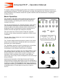
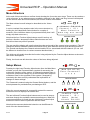
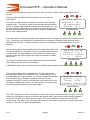
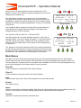
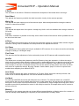
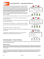
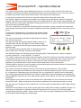
Universal RCP Operation Manual Universal RCP – Operation Manual Index General Description ......................................................................................................................................... 2 Data System Description ................................................................................................................................. 2 Basic Operation ............................................................................................................................................... 3 Menu Structure ................................................................................................................................................ 4 Setup Menus .................................................................................................................................................... 4 Main Menus ..................................................................................................................................................... 6 ENG Menus ..................................................................................................................................................... 7 Aux Menus ....................................................................................................................................................... 9 Fixed Operation ‘ Action’ Buttons .................................................................................................................. 10 3D Operation - General ................................................................................................................................. 12 Operation with the Camera Corps Multi-Camera Keypad ............................................................................ 14 Macro Group Memory Storage with Multi-Camera Keypad .......................................................................... 14 ADDENDUM .................................................................................................................................................. 16 RCP Panel - Master Set-up Menus ........................................................................................................... 17 RCP Panel - Main Menus .......................................................................................................................... 18 Typical Configuration Diagrams Connector Wiring Details ........................................................................... 19 RCP Panel - Eng Menus ........................................................................................................................... 19 RCP Panel - Aux Menus............................................................................................................................ 20 RCP - Specifications ...................................................................................................................................... 23 V3.1 Page 1 22/12/11 Universal RCP – Operation Manual General Description The Camera Corps Universal RCP provides comprehensive control of many different makes and models of video camera. Up to six cameras of different makes and models can be controlled from a single panel. The data output can be distributed on a single audio cable over long distances to the camera locations providing a very versatile system of control. The control functions are not limited by any particular camera type. The menus are automatically adjusted for different camera models, to provide virtually all of the remote control facilities provided by any given manufacturer, including on screen displays for less frequently used functions. Up to two 3D rigs (four cameras) may be controlled utilising a special mode of operation. In this mode individual cameras may be controlled normally on their channel select buttons. However, a third channel button can control both cameras together maintaining any control value offsets between the two cameras. This is possible for all available camera makes and models on the control panel. The RCP can be fully integrated into Camera Corps other remote operation equipment and is designed to work either standalone, or in conjunction with the PTZF Joystick controllers also available from Camera Corps. In fact, the RCP has the ability to adjust the pan, tilt, zoom and focus of cameras mounted on remote heads to provide preset shots without the need for a remote joystick panel. External inputs are provided to allow cue/tally information for all six channels to be input to the system. Provision is also made for remote channel selection, and remote monitor switching if required. From software version 2.0 onwards the RCP can be controlled from the Camera Corps multi-camera keypad providing control for up to 96 cameras. (Not it 3D modes though). Data System Description Unlike most serial data control systems, which use high-speed digital signals, the Camera Corps system uses modems to convert the digital data into audio style tone signals before transmission. This has many advantages, which include virtually no limit on distance, as well as easy transmission over simple RF links and telephone lines. By using balanced transformer coupling at both transmission and receiving points, earth loops and hum problems are virtually eliminated. Standard audio cables or CAT5 data cable can be used for data transmission. The data is simply ‘paralleled’ using XLR3 splitters for transmission to multiple cameras/heads. The transmission data rate can be set on all sending devices to 1200, 2400 or 4800 baud. 2400 baud is normally used, with 1200 being necessary for some RF and telephone systems, or very long cable runs. All receiving devices will auto detect the incoming baud rate after receiving a few initial bytes of data. Data from the RCP is sent to the remote head operator’s position where it is mixed with data from the Pan, Tilt, Zoom and Focus controller. From here the data is split and sent to the remote head/camera locations where it is decoded by Interface Boxes into analogue signals for the P&T head, and the correct data format required by particular camera makes/models. The interface boxes have a channel selector switch that enables them to detect and decode only the data intended for that particular channel. V3.1 Page 2 22/12/11 Universal RCP – Operation Manual To assist in testing and setting up the system it is possible to generate data test signals in the form of cue/tally light commands. The RCP will generate a cue/tally command from the ‘cue test’ action button which will light the cue indicator on both the Joystick controller and the interface box if everything is working correctly. Basic Operation The operation of the RCP is fairly intuitive but there are some basics that are described here to speed up and simplify the overall operation. The drawing here shows the layout and controls of the RCP. The top row of buttons are for ‘Channel Selection’. Each button can be allocated a particular camera make and model and whenever data is sent with a particular button selected, then an assigned ID code for that button will only be accepted by an interface box with that particular channel ID selected. The next row are the ‘Action’ buttons. Each has a specific function and are always operational regardless of which menu is selected. The two ‘Menu Select’ buttons are used to step through the various menu screens. The ‘Function Adjust’ buttons will perform actions on the items shown in the current menu. Usually this will be an increase or decrease in the value displayed. 3D Channel 1 3D Channel 2 L R L+R L R L+R 1 2 3 4 5 6 BLACK BAL CUE TEST OSD BARS UPDATE WHITE CAMERA BAL MENU SELECT Hitachi DK–H32 Channel 1 ID 1 Menu Selection Main Eng Aux Setup FUNCTION ADJUST The ‘Gain/Black’ buttons is used for changing the red and blue knobs from controlling the colour gains of a camera to controlling the colour blacks if that function is available. The smaller knob to the bottom left is the ‘Master Black’ control, and the larger knob to the right is the ‘Iris’ Control. The ‘Auto’ button just above it used to select an auto iris function. The operation of this is described more fully for each different camera type as the way it works will depend on the camera type being controlled. GAIN / BLACK AUTO Note that the illumination of the Menu Select and Function Adjust buttons will change depending on the menu displayed. If a button is lit then it will perform some function. If it is not lit then it will have no effect. The Gain/Black button always defaults to colour gain control and if selected to ‘on’ for colour black control will default back to ‘off’ after about 10 secs if no control is moved. V3.1 Page 3 22/12/11 Universal RCP – Operation Manual Menu Structure At the end of this manual there are flow charts showing the four main menu trees. These can be used as a ‘quick reference’ to see what menus are available, although for the ‘Main’ and ‘Eng’ menus it will depend on the camera make and model selected, as to which menus are available. The Menu shown here will always be described as the ‘Home Menu’. It can be reached from anywhere else in the menu structure by holding the Left Hand Menu Select button for a couple of seconds. (If the Left Menu button is just pressed briefly then it will simply step back one menu.) MENU SELECT Hitachi DK–H32 Channel 1 ID 1 Menu Selection Main Eng Aux Setup FUNCTION ADJUST Note that the four Function Adjust buttons are all lit as they all perform a function, whereas the Menu Select buttons are not lit and will not have any effect if pressed. The top row of the display will usually show the make and model of the camera being controlled. (This will change as different Channel buttons are selected if they have different camera types allocated to them.) The second row displays the Channel selected and the ID no. associated with that channel. (ID nos. can be different to channel nos. for various reasons described later.) The third row will usually describe the function being adjusted by the Function Adjust buttons as shown in later menu descriptions. Finally, the fourth row will show the values of the items being adjusted. MENU SELECT Setup Menus Pressing the right hand Function Adjust button from the Main Menu will take you into the Password Menu required for accessing the main setup functions of the system. A Password protected menu is required to access and change any of the functions which might be considered ‘fatal’ to the operation of the system if changed by somebody who does not fully understand the implications of changes to these settings! The Password is entered using the Channel Select buttons, and the actual password is provided when purchasing an RCP. When the correct password is successfully entered the camera selection screen is displayed as shown here. The two left hand Function Adjust buttons can be used to step up and down through the available camera manufacturers. When the correct manufacturer is found, the two right hand Function Adjust buttons are used to select a particular camera model. MASTER SETUP Enter Password? * * * * FUNCTION ADJUST * MENU SELECT CAMERA TYPE Channel 1 ID 1 Make Model Hitachi DK–H32 FUNCTION ADJUST Note that the camera make/model selection can be different for each of the six channel buttons. V3.1 Page 4 22/12/11 Universal RCP – Operation Manual Also note that any changes made in this menu will reset all the camera values and settings to their defaults. MENU Press the right hand Menu Select button to move on to the next Setup Menu. This menu is used to assign a particular ID number to the selected channel button. This can be useful where the cameras and interface boxes are already rigged with the interface box ID’s already set. If the operator wants to change the order in which the cameras appear on his channel buttons then this can be done by simply re-assigning the ID’s for each channel button. SELECT MASTER SETUP Channel 1 ID 1 ID Assignment Normal ID 1 FUNCTION ADJUST It is also possible using the left hand function adjust buttons to change from ‘Normal’ ID’s to Multi-Camera ‘ ID’s. This allows up to 96 different ID addresses to be used when controlling more than just the six available from this RCP. An add-on keypad unit can be connected to provide switching for up to 96 cameras. MENU SELECT The next Setup Menu allows adjustment of the Audio Data output level. The default setting of 4 provides a 1volt pk to pk signal which will work in most setups. For long distances or cases where six cameras are paralleled onto the output a higher level may be required for reliable data control. The right hand buttons set the output data baud rate. Note that both these settings are the same for all channels. MASTER SETUP Channel 1 ID 1 O/P Level TX Baud 4 2400 FUNCTION ADJUST A 9600 baud setting can be used to provide an RS422 output instead of using the Audio data output. The next Setup Menu has two adjustments. The left hand buttons select between ‘Enabled’ or ‘Disabled’ for the camera timing. This is set independently for each channel. If a camera has genlock available then this will be set to ‘Enabled’ by default. However, in some situations if two RCP’s can be controlling the same camera it may be necessary to disable the timing on one RCP prevent having to make the timing settings identical in each control panel. MENU SELECT MASTER SETUP Channel 1 ID 1 Timing PTZF Enabled Connected FUNCTION ADJUST The PTZF setting can be either ‘Connected’ or ‘Not in use’. When sending data from the RCP via a PTZF joystick (for controlling a camera on a remote pan and tilt head), gaps must be left in the data stream to allow the PTZF data to be added into the stream. This can slow down the data rate from the RCP unnecessarily if the data is going directly to the cameras. If the data is not going to a Joystick panel then set this to ‘Not in use’ to speed up data transfer. V3.1 Page 5 22/12/11 Universal RCP – Operation Manual Next is a menu to allow adjustment of the contrast of the LCD display. This can vary in different ambient temperatures and can be adjusted as necessary here. The ‘Warn Beep’ function can be turned on or off if it becomes annoying! When a button is pressed for some function which is not available for a particular camera model there will be warning screen displayed for a few seconds accompanied by a ‘beep’ if it is enabled in this menu. MENU SELECT MASTER SETUP Channel 1 ID 1 Contrast Warn Beep 8 Enabled FUNCTION ADJUST The final Setup Menu (shown by the fact that the right hand menu select button is not lit) provides the settings for 3D modes and Keypad operation of RCP operation. The choices for 3D are ‘Non 3D’, ‘1x3D’ and ‘2x3D’. Non 3D provides for six normal individual channels. 1x3D sets up channel buttons 1,2 & 3 as a single 3D system. 2 x 3D sets up all six channel buttons to provide 2 complete 3D control systems for four cameras. See the section later in the manual for a full description of 3D operation. The ‘Keypad’ on/off mode switches the RCP from being controlled by the six camera select buttons, to being controlled by a Camera Corps Keypad unit. This increases the number of channels from six to ninety six. See later in the manual for a full description of this feature. MENU SELECT MASTER SETUP Channel 1 ID 1 3D Setup Keypad Non 3D Off FUNCTION ADJUST Main Menus The Main menus are accessed by pressing the left hand function adjust button from the Home Menu. These menus provide control of all the most frequently used camera functions such as gain, shutter etc. The list shown here comprises all of the possible menus available in the RCP, but those displayed at any given time will depend on the make/model of camera selected. Filter ND Controls selection of camera ND Filter wheel positions. Filter CC Controls selection of camera colour filter wheel positions. Gain Selects master gain values. Step values depend on camera make/model. Shutter Sets shutter values. Detail Adjusts overall detail or sharpness setting. Note that other detail adjustments may be available in the Eng menus, or by using the On Screen Display system where cameras have those available. Chroma Adjusts the overall camera picture saturation level. V3.1 Page 6 22/12/11 Universal RCP – Operation Manual IR This selects an infra-red mode for a camera if available. It may also lead to an ‘auto’ mode where the threshold at which the infra-red mode switches on and off automatically can be adjusted. AWC Mode This selects the colour balancing mode of the camera. Typical settings would be ‘Manual’ for allowing use of the colour control knobs to manually set the colour. 5600k, or 3200k will set preset colour values for lighting of those colour temperatures. ATW or Auto will allow automatic colour control by the camera itself based on the average picture content. Preset will allow use of the ‘White Bal’ function button to set the camera colour temperature while looking at a white chart. See individual camera descriptions for checking the functions available. Gamma Changes the picture gamma settings. This adjusts the relative brightness of the dark areas of a picture compared to the overall picture level. Increased gamma values may show more noise in the dark areas of the picture. Knee This reduces the gain of the picture at high brightness levels. Mostly used to show more detail in very bright areas such as when shooting indoors but also showing a very bright window in the picture. There is usually an ‘Auto’ setting offered by the camera. Peak/Average This setting will usually only have an effect when in an ‘Auto’ iris mode. Here the camera will be using the image itself to adjust the exposure to give the best picture. It can either use the ‘Peak’ value of a small part of the picture to set the exposure, or the ‘Average’ value of the picture brightness, or various settings in between those extremes. Note that with most cameras the main iris knob will still have an effect on the ‘Auto’ exposure to trim the final exposure to your preference. Iris Area This setting works in a similar way to the previous Peak/Average adjustment. However, this will select a particular part of the picture to be used for setting the ‘Auto’ exposure level. Usually the ‘centre’ are is used but for particular images it be better to ignore the top of the picture if it contains a very bright sky for instance. Iris Speed Again, this is used only for ‘Auto’ modes of exposure. This controls the speed at which the iris (or auto shutter maybe) responds to changes in picture brightness. When the auto exposure is done by actually moving the physical iris on a lens, then it can be very useful in preventing ‘hunting’ of the iris at high f stops. ENG Menus The ENG (engineering) menus are accessed from the Home menu by pressing the second function button from the left. These menus are less frequently used actions which will probably only require setting once for a particular camera type. The complete list of possible menus is shown here, but again only those provided by a particular make/model of camera will be displayed in normal use. H Detail This will set the amount of horizontal detail correction applied to the picture. In conjunction with the overall detail setting in the main menus it can help to improve the apparent sharpness of the final image. V3.1 Page 7 22/12/11 Universal RCP – Operation Manual V Detail This is similar to the above H Detail but increases the sharpness of horizontal lines in an image. Detail Band This adjusts the frequency at which the detail correction circuitry in the camera operates. White Clip This adjusts the white clipping level of the camera output. Must be adjusted while viewing the camera output on a waveform monitor. Aspect This adjusts the aspect ratio of the picture. Usually only 16x9 or 4x3 are available when using a camera in SD mode. Format With some cameras it is possible to remotely set the video format of the camera. Where possible this can be done from this menu. H Phase This will adjust the horizontal timing of the camera signal with respect to a genlock video reference signal. Note that ‘Timing’ must be enabled in the Setup menu for this adjustment to work. Col Phase The adjustment of colour phase will only be available for SD cameras. It is a coarse correction and usually changes in 90deg or 180 degree steps. Fine Phase This provides the fine adjustment of colour subcarrier phase for SD cameras with composite outputs. Abs/Rel The default here is always Abs (Absolute) with Rel (Relative) being the alternative. It affects the way in which the four control knobs adjust the camera colours, master black and iris. In absolute mode the knobs send an absolute value to the camera (shown briefly on the LCD display). With relative mode selected only increase or decrease commands are sent. This can be useful in a setup where more than one RCP has control of a particular camera. By using ‘Relative’ mode sudden ‘jumps’ in colour or exposure are avoided when adjusting from different RCP’s. Auto Setup Some cameras provide the option of performing a ‘Full Auto Setup’ where the camera performs a full check on all it’s internal adjustments. This can be started from this menu. Iris Mode For cameras with ENG lenses this will always be set to ‘Normal’. For cameras which use a small DC motor to drive the iris of a lens which does not have it’s own motor drive, this can be set to provide either a direct drive for the motor from the Interface Box, or a positional DC output voltage which can drive a servo amplifier to provide full positional iris control. It will mostly be used for 3D setups which use DC motors to drive the lens iris . Masking Depending on the camera type this can choose different preset Masking (or Matrix) values for a camera. It can also usually switch Masking off completely so that the difference is easily visible. V3.1 Page 8 22/12/11 Universal RCP – Operation Manual Aux Menus The Aux menus are accessed by pressing the third function button from the left while the Home menu is displayed. These Aux menus provide access to switch functions such as Wash, Wipe etc and the Pan, Tilt, Zoom and Focus controls for adjusting a remote head if it is being used. These Menus are the same for all camera types with functions that are not available for a particular camera appearing blank The first Aux menu provides access to the PTZF (Pan, Tilt, Zoom, Focus) controls. Also, single function button presses here will operate remote Wipe, Wash and switch functions. These will only be available on certain types of remote head, usually the weatherproof housing systems. After selecting PTZF, the screen shown here is displayed saying ‘Use knobs to Adjust’. MENU SELECT Hitachi DK–H32 Channel 1 ID 1 PTZF Wipe Wash SW1 FUNCTION ADJUST The red knob will then adjust the Pan, and the Blue knob will adjust the Tilt, assuming there is a pan and tilt head connected and on the selected ID number. Pressing the Gain/Black button will change the display to show ‘Zoom and Focus’. These can now be adjusted using the same red or blue knobs. Note that when controlling the colours, the Gain/Black function will default back to Gains after a preset time, here the Zoom and Focus selection remains until either the button is pressed again to return to Pan and Tilt, or the menu is exited using the left hand Menu Select button. MENU SELECT Hitachi DK–H32 Channel 1 ID 1 Use Knobs to Adjust PAN TILT FUNCTION ADJUST During PTZF operation the Master Black and Iris controls continue to function normally. Pressing the right hand Menu Select button will move on to a new menu which will be dependent on whether Pan and Tilt or Zoom and Focus was selected. GAIN / BLACK If Pan/Tilt was selected then there are two further menus which are used to set the Pan and Tilt endstops. This can be useful if there is no operator at the Joystick position and the endstops need to be set or disabled for some reason. From the Zoom and Focus menu, there are also two further menus which can be accessed. These are for Zoom Drift adjustment and Focus Offset adjustment. Moving back to the first Aux Menu (PTZF, Wipe, Wash, etc.), pressing the right hand Menu Select button from here takes you further into the Aux Menus. SW2 is another button which can activate a remote switch function at the interface box. V3.1 Page 9 22/12/11 Universal RCP – Operation Manual The Iris button would normally be used where a lens has a small DC motor to drive the iris. This would allow ‘Normal’ or ‘Reverse’ to be selected so that when operating the main iris control knob the direction of the motor can be changed. There are many possible reasons why the iris might be rotating in the wrong direction in this situation so the selection is provided to ensure that clockwise rotation of the iris knob increase the exposure and anti-clockwise rotation reduces the exposure. The two dashed lines and the fact that the function button here is not illuminated show that this camera type does not have this function available. MENU SELECT Sony Q-Ball IR Channel 1 ID 1 Iris Foc Mono SW2 -- Man Off FUNCTION ADJUST The Focus option will set either ‘Manual’ or ‘Auto’ Focus for some types of lens. The Mono option can be used to set some camera types produce a monochrome picture. The next menu provides some more functions which may be available for certain camera types. Stab will switch lens stabilisation on or off if that function is available. Frz will freeze the camera picture if the camera has that function builtin. MENU SELECT Sony Q-Ball IR Channel 1 ID 1 Stab Frz Neg Pwr -Off Off On FUNCTION ADJUST Neg will switch the picture to a negative image. Pwr will switch the camera power On or Off when this is provided as a remote control function by the manufacturer. MENU SELECT Finally the last Aux Menu allows the picture to be ‘Flipped’ either horizontally or vertically if the function is available. Sony Q-Ball IR Channel 1 ID 1 HF l i p VF l i p Off Off FUNCTION ADJUST Fixed Operation ‘ Action’ Buttons This row of buttons perform specific functions which are frequently used and so have individual buttons available to allow quick access. Update Camera The update camera button is used to send a complete copy of all the RCP settings to the camera on any selected channel. This includes values set by the colour gains and blacks, master black, iris and auto iris values. It may also send a command required by a particular camera type to set that camera into remote control mode. For these reasons it is important to use this button at any time after a camera has been switched off and on again. If in doubt press the update button! Usually there will be no visible change in the picture when this button is pressed as you will simply be sending the same command values that the camera has already set. V3.1 Page 10 22/12/11 Universal RCP – Operation Manual It also provides a quick way to get the camera back to particular settings if it has been switched off over night. White Balance The white balance button does just what you would expect, it starts a white balance operation. With quite a few of the small minicams this is only possible when the AWC mode is set to a mode where the manual controls do not work. This is clearly a bit of a disadvantage as manual operation is nearly always required in outdoor situations. If you try to do a white balance in a mode where it is not allowed you will get a warning message on the screen and a ‘beep’ if these are enabled. Black Balance This function is available for most of the minicams but in cases where a small DC lens is used which does not have an iris controlled directly by the camera, you must manually close the lens iris before performing this function. With some camera types this operation will also hide any pixel defects in the camera. Cue Test The Cue test button generates a cue/tally light which is sent over the data system. This can be very useful when setting up multiple cameras for identifying that data is working properly and ID nos. are set correctly. Where a PTZF Joystick panel is being used to control a remote head then the cue/tally light will display on that panel to show that data is reaching that point and then be passed on to the interface box(es) to show that they are receiving data on the correct ID number. OSD OSD stands for On Screen Display. Some cameras provide this function to allow access to many less frequently used settings. These might include complex detail settings, masking values, etc. and many other features. Always check the camera handbook to see what extra features might be adjustable through the OSD menus. When the OSD button is pressed, a new LCD menu screen will appear allowing the function adjust buttons (and sometimes the right hand menu select button) to move through the camera menu screens now visible on the picture. Note that with some cameras this button has a ‘toggle’ action rather than an on/off action. In this case the button will not stay lit when the OSD is displayed on the camera picture. In these cases to turn off the OSD simply press the button again to remove the display from the picture. Then press the left hand menu select button to remove the special LCD menu and return to the normal menu screen. Bars The Bars button is used to switch the camera from picture to bars output. As with the OSD button some cameras have a ‘toggle’ action here and the button does not remain lit when bars are displayed. In the case of the Toshiba cameras both the bars and OSD buttons have the same function as in this case the camera steps through a sequence of Picture > Bars > OSD. Gain/Black The gain/black button is used to change the function of the colour control knobs from adjusting the colour gains to adjusting the colour blacks. With modern cameras colour black adjustment is rarely required (and frequently not available anyway). If the button is pressed to enable black control then after about 10 seconds of no control movement, it will switch back automatically to colour gain control. V3.1 Page 11 22/12/11 Universal RCP – Operation Manual Auto The Auto button just above the Iris control is used to set the camera to auto exposure control. Depending on the camera type this may be done using the normal lens iris to control exposure based on picture content. There is usually about ±1 stop override available on the iris control set the ‘aiming point’ of the overall exposure. With some cameras the shutter (and/or gain) is used to set the auto exposure. In this case the Shutter display may change to show ‘Auto’ or ‘ELC’ until the control is returned to normal. 3D Operation - General The 3D operation mode is a very powerful way to control two cameras which need to be adjusted together, but not necessarily with the same control values. The Camera Corps system is designed to be completely versatile in the way this is achieved, but a full understanding of how it is done is required to get the best from the system! Each of the two possible 3D channels uses three of the channel select buttons, either 1,2 &3 for a single 3D channel, or 4,5 & 6 for a second 3D channel. If only one 3D channel is required then channels 4,5 & 6 will operate as normal single camera control channels. MENU SELECT Hitachi DK–H32 Left Chan ID 1 Menu Selection Main Eng Aux Setup FUNCTION ADJUST The display will always show if you are controlling a channel which has been defined in 3D mode. As shown here the second line of the display will show LEFT, RIGHT or LEFT + RIGHT. In the last case (channel 3 or 6) both ID’s will be shown on the display. Operation When operating the left or right channel, exactly the same functions will be available as for ‘normal’ single camera control. Apart from showing Left or Right in the second line of the display, all the displays will be normal as well. When selecting the Left + Right channel (3 or 6) though, operation will be different. Here, any changes made to values using the Function buttons will send data to both cameras. For instance if you want to increase the Master Gain then doing this with channel 3 selected will send the new Master Gain value to both ID’s shown on the display. There will be a slight delay as the data to each ID is sent sequentially. Note that the same values are always sent to both channels when controlled in this way. If you actually want different Master Gain values for each camera then this will have to be done by setting each channel separately. MENU SELECT Hitachi DK–H32 Left+Right 1 2 RED GAINS BLUE 17 19 -12 -15 FUNCTION ADJUST The variable controls such as colour gains, master black and iris will also change together when the Left + Right channel is selected. However, if an individual channel has been adjusted to offset the variable settings between the two cameras, then adjustments made using channel 3 will maintain any offsets created between channels 1&2. In the case of variable controls the display will show both Left and Right channel values being sent. V3.1 Page 12 22/12/11 Universal RCP – Operation Manual Setting Up Select ‘Setup’ from the Home Menu and then choose the required camera type for the first 3D channel while the Channel 1 button is selected. If a second 3D channel is MENU required, select the required camera type for this with channel 4 SELECT selected. Note that only the Left channel camera type needs to be set manually at this stage. MASTER SETUP Now use the right hand menu select button to move through the setup menus until reaching the last one which is shown here. Use the left two function buttons to choose either ‘1 x 3D Chan’ or ‘2 x 3D Chan’ depending on the number of 3D channels required. Channel 1 ID 1 3D Setup Keypad Non 3D Off FUNCTION ADJUST Then press the left hand menu select button to exit this menu. There will be a slight delay and a message saying that the 3D modes are being configured before moving back to the previous Setup Menu. (Or moving directly to the Home Menu if the button is held for more than a couple of seconds.) At this point any other settings can be made such as ID allocation etc. The 3D setup automatically disables the PTZF function as it assumes the data will not be passing through a joystick controller. This can be enabled if required though. General Rules for 3D operation Changes made to Left channel values will also change the Left + Right values shown in the display of channels 3 and 6. Changes made to the Right channel will only be made on that channel. Changes made to the Left + Right channel (3 and 6) will affect both channels which become the same value. Also, if a change to a value is made to Left + Right, then the menu display for the Left and Right individual channels will become the same the next time either of those channels is selected. Certain functions are not available from the L+R channel. (Usually for obvious reasons). These include IR on/off, Abs/Rel, White Clip and Timing adjustments. These must all be adjusted on their individual channels. When adjusting the variable control knobs the adjustment will stop whenever either channel reaches it’s maximum or minimum value. Note that it is important to set the ‘Iris Mode’ correctly when using a small DC motor to drive the lens iris directly without positional feedback. In’ normal’ mode only the Left channel output is driven as this assumes there is some mechanical link between the two irises. In ‘Mode 1’ both of the analogue outputs are driven and maintain any offsets created by individual channel adjustments. In this case it is assumed that small servo amplifiers drive two DC iris motors with positional feedback. These output have a range of 0-5v from the Double Interface Box. To restore ‘normal’ operation after having had 3D modes in operation, simply go through the setup menus as before and restore the 3D setting to ‘Non 3D’. After doing this it is important that you restore individual channels to their default settings by de-selecting and re-selecting the required camera type in the setup menu. V3.1 Page 13 22/12/11 Universal RCP – Operation Manual Operation with the Camera Corps Multi-Camera Keypad The Multi-Camera Keypad expands the number of cameras that can be controlled from 6 to 96. A single Keypad may be connected to both a Joystick controller and an RCP at the same time, or the Joystick and RCP may have separate Keypads to control them independently. It is not possible to setup 3D camera control modes when using the Keypad mode of operation. The connection is made using an adapter cable from the ‘CCU Panel’ socket on the Keypad unit to the ‘Keypad’ connector on the RCP. This cable should be a 9way ‘D’ Male to Male with all pins wired. When the RCP is not mounted in the desktop box, then a special cable is used with a 9way ‘D’ Male at the Keypad end and a 10way IDC connector at the RCP. This cable is wired 1 to 1 with pin 10 of the IDC being unused. Never plug the interconnection cable into the RCP while it is powered as this may cause damage to the unit. With the Keypad connected to the RCP, switch on the RCP (which also powers the Keypad). Normally the RCP will automatically detect that it is connected to a Keypad and will display ‘MultiCam Keypad Connected’ for a few seconds. This can be confirmed by the fact that none of the Channel buttons will be illuminated. In the case of some RCP’s with older hardware, the detection may not be automatic and then the Keypad Operation Mode can be set using an option in the ‘Setup’ Menu. Select this Menu in the normal way and use the right hand menu button to move to the last menu available. Select Keypad to ‘ON’ and the channel buttons should all be unlit showing control is now from the Keypad. Press the channel up/down buttons a couple of times on the Keypad unit and then after initialisation the RCP ID indicator will start following the Keypad selection. Note that all control of Channel ID’s is now transferred to the Keypad and options on the RCP menus for selecting Normal / Multicam ID’s and ID nos. will be disabled. Note that if feeding the RCP data into a Joystick controller that is also being controlled from a Keypad then the baud rate must be selected to 2400 baud. If the Keypad option is selected manually from the Setup Menu then it must be set to OFF again when the RCP is next used without the Keypad control. Macro Group Memory Storage with Multi-Camera Keypad A new feature introduced in V3.0 of the RCP is the ability to store up to 6 groups of camera ID’s. Each of the 6 groups can store up to 16 ID’s. There can be two completely different setups for each camera in a group. Either of the two setups can be recalled at any time from a single button press without changing the camera selection which is currently being controlled. The channel select buttons on the RCP are used to select the individual groups. (Normal channel selection is done using the Keypad.) V3.1 Page 14 22/12/11 Universal RCP – Operation Manual The channel select buttons will be displayed as green for one set of values and red for the other set. Pressing the channel select button will change the button colour from green to red or vice versa, and at the same time send the new camera data to each of the camera ID’s in that group. If a group has no camera ID’s stored in it then that channel select button will remain unlit. The camera settings for each group are made in the normal way by selecting the camera ID using the Keypad. The colour of the channel select button (if it contains the ID of a the camera being adjusted), will show whether the values being adjusted are being stored in the ‘red’ or ‘green’ state of any cameras that may be stored in a particular group. There is no restriction on a particular ID being stored in more than 1 group. In practice this means that more than just two states may be stored for a particular camera by allocating it’s ID to more than just one group. A new menu is available when in Keypad mode which provides the facility for setting up the groups and the camera ID’s stored in them. This menu is accessed by pressing the right hand menu button from the main top menu. The top line shows the currently selected ‘Macro’ group no. A channel button will also be lit green to show which group is selected. To change the selected group simply press a different channel button. MENU SELECT MACRO GROUP 3 Keypad Mode IDM8 M5 3 Total 6 Add Step Full Clear FUNCTION ADJUST The second line shows that the RCP is in Keypad mode and which channel ID is currently selected on the keypad. The third line shows one ID already stored in this group (M5). Press the function 1 button to add the currently selected ID – in this case M8 – to Group 3. The number 3 above the word ‘Step’ shows the position of this ID in the group. Press the function 2 button to step through all the ID nos. stored in Group 3. The number to the right of the word ‘Total’ shows how many ID’s are currently stored in Group 3. In practice the order in which the ID’s are stored is not important, it just determines the order in which camera data will be sent on the data line. Function button 4 performs a ‘clear’ operation on the selected group and removes all the ID’s stored in this group allowing a new set of ID’s to be allocated. The function 3 button can change each of the ID entries in the group between ‘Full’ and ‘Part’. When the camera data is transmitted to each camera ID it can take quite a long time if there are a large no. of cameras in a particular group. By selecting ‘Part’ for a particular ID, this time can be reduced by only sending important data functions to the camera. Which data is sent will depend on the camera type being updated but in practice the ‘Part’ data would comprise, Gain, Shutter, Iris, IR mode, and Red & Blue colour data. Note that when ‘group’ data is sent on the data line this is transmitted in a more continuous form than normal RCP data – again to reduce the time it takes to update all of the selected cameras in a group. This will reduce the response of the Joystick Pan, Tilt, Zoom and Focus data while the RCP data is being transmitted. Note that it is important to set up all the camera types on the RCP before creating any Macro Groups. If a camera type is changed for a particular ID which is already stored in a group, then it will not update correctly using the group function. Simply ‘Clear’ the ID’s from any group containing this ID and then add the ID’s back in after changing the camera type. V3.1 Page 15 22/12/11 Universal RCP – Operation Manual ADDENDUM There are a number of ‘special’ features which can be accessed which have not been described above. These can be accessed by holding down the ‘Auto’ button and then pressing one of the channel buttons to perform the action. AUTO + Channel 1 button:This displays the serial no. of the RCP. AUTO + Channel 2 button:When upgrading from the standard RCP to the 3D version you will need to enter a code to activate the 3D modes. Pressing AUTO + Channel 2 button will show a screen on which to enter the activation code. Once activated the 3D modes will stay permanently available. AUTO + Channel 3 button:This action will toggle the requirement for a password when accessing the ‘Setup’ functions. Not having the password feature enables much faster setting up of multiple cameras. Once setup, the password feature should be re-enabled if the RCP is being operated by somebody who does not fully understand the system! AUTO + Channel 4 button:This feature makes it possible to disable some of the ‘Action’ buttons to prevent inadvertent operation. The action will toggle the buttons between enabled and disabled. The buttons affected are – White Bal, Black Bal, OSD and Bars. The ‘Update Camera’ and ‘Test Cue’ buttons are left unaffected as they will generally not cause a change in the picture. Resetting the RCP memory:In the unlikely event of a major software crash it is possible to do a ‘factory reset’ of the RCP internal software memories. To do this simply hold down the two ‘Menu Select’ buttons above the LCD at the same time as pressing the Reset button (on the side of the PCB), or switching on power to the unit. Release the buttons when you see a display counting up as the memories are reset. V3.1 Page 16 22/12/11 Universal RCP – Operation Manual RCP Panel - Master Set-up Menus Sony Q-Ball IR Channel 1 ID 1 Menu Selection Main Eng Aux Setup This main menu select screen can be reached at any time by repeated presses of the top left menu button. Note that if a ‘menu’ or ‘function’ button is illuminated it will perform some action. If unlit it will have no effect. MASTER SETUP Enter Password? Before proceeding with the set-up menus a password must be entered. This is because any incorrect settings here may cause complete loss of control of a particular camera. These settings should only be made by somebody who understands the system! The password is entered by pressing the channel buttons in the correct sequence. MASTER SETUP Channel 1 ID 1 O/P Level TX Baud 4 2400 This screen allows setting of the data level for the Audio Data O/P. Range 0-15. Default 4 for 1v pk to pk output for a single 600ohm load. The TX Baud rate can be set here. Note that both these settings apply to all channels, not just the selected one. 9600baud can be selected which inhibits the Audio data output and generates an RS422 style data output. Macro Group 1 Keypad Mode ID M1 M23 3 Total 8 Add Step Full Clear CAMERA TYPE Channel 1 ID 1 Make Model Sony Q-Ball IR First select the channel to be set. Now using the left hand two function buttons scroll through the list of available camera makes. Next select the required camera model. Select a different channel to set another camera type for that channel. Note that any changes made here will set the channel to it’s default values MASTER SETUP Channel 1 ID 1 Timing PTZF Enabled Connected This screen allows setting whether timing data is sent to the camera or not. It may be necessary to inhibit timing data if multiple RCP’s are being used. The PTZF setting should be set to ‘Connected’ if the RCP is working into a Joystick PTZF controller. This reduces the data rate to allow PTZF data to be added. If the RCP is feeding directly into a camera then set ‘Not in use’ to allow maximum data rate to be used. Both of these settings can be set individually for each channel. This menu is only available in ‘Multi-Camera Keypad’ mode. It is used to set the Macro Group storage ID’s. See the ‘Multicamera keypad operation’ section of the handbook MASTER SETUP Channel 1 ID 1 ID Assignment Normal ID 5 This screen allows the interface box ID to be assigned to the selected channel no. The left hand buttons select between ‘Normal’ or ‘MultiCamera’ style ID’s. ‘Normal’ ID’s can be in the range 1-8 and ‘Multi-Camera’ ID’s in the ranges 1-8, 11-18, 21-28, - up to 111-118.‘Normal’ and ‘Multi-Camera’ ID’s can be mixed for different channels if required. MASTER SETUP Channel 1 ID 1 Contrast WarnBeep 8 Disabled This screen is used to adjust the contrast of the LCD display. The ‘Warn Beep’ can be enabled or disabled here. This is an audible warning if you try to access something which is not available and the LCD display will show a message describing the reason. MASTER SETUP Channel 1 ID 1 3D Setup Keypad 1x3D Chan Off This screen is used to setup the 3D modes of operation. It is possible to select either 0, 1 or 2, 3D channels. The channels are not finally set until you exit this display using the left menu button. See the handbook for a full description of 3D operation. When using a keypad to control up to 96 cameras the 3D Setup will be disabled. In most cases the RCP will auto detect a Keypad connection but if not then it can be enabled or disabled using this menu. V3.1 Page 17 22/12/11 Universal RCP – Operation Manual RCP Panel - Main Menus Hitachi DK-H100 Channel 1 ID 1 Menu Selection Main Eng Aux Setup Hitachi DK-H100 Channel 1 ID 1 Filt ND Filt CC Clear 5600k Performs filter changes for both ND and colour filters when these are available. Hitachi DK-H100 Channel 1 ID 1 IR AWC Mode Off Manual IR sets various modes of infra red operation. Usually Off/On/Auto. AWC Modes set the operation mode of the colour balancing. Manual, Auto, Fixed etc. This main menu select screen can be reached at any time by holding down the top left menu button. Note that if a ‘menu’ or ‘function’ button is illuminated it will perform some action. If unlit it will have no effect. Note that not all menus shown here will appear for all camera models. Only those allowed by the Manufacturer will be shown. Hitachi DK-H100 Channel 1 ID 1 Gain Shutter 6db 1/250 Hitachi DK-H100 Channel 1 ID 1 Detail Chroma 3 5 Gain sets the camera master gain and Store Recall Shutter sets the shutter values. Detail sets the overall camera sharpness. Store Recall Chroma sets the camera colour saturation level. Hitachi DK-H100 Channel 1 ID 1 Gamma Knee 3 Auto Store Recall Gamma allows changes to the gamma setting of the camera. Knee can usually be set to either ‘Auto’ or other values to determine the overall Knee level. Hitachi DK-H100 Channel 1 ID 1 Pk/Av Iris Area Even Centre Pk/Av changesStore the way the autoRecall iris works, with Peak setting the operation on small highlight peaks, and Average allowing the auto iris to work on the average picture brightness level. Somewhere in between is usually best. Iris Area sets the part of the picture being assessed for Auto Iris Level. Hitachi DK-H100 Channel 1 ID 1 Iris Speed 0 Iris Speed sets the speed of the iris response when in ‘Auto Iris’ mode. This can be useful to reduce ‘hunting’ of the iris in certain lighting conditions. V3.1 Page 18 22/12/11 Universal RCP – Operation Manual RCP Panel - Eng Menus Hitachi DK-H100 Channel 1 ID 1 Menu Selection Main Eng Aux Setup Hitachi DK-H100 Channel 1 ID 1 H Detail V Detail 8 8 Sets H & V Detail values. Note that more settings for detail can usually be found in the On Screen Display Menus. Hitachi DK-H100 Channel 1 ID 1 H Phase ColPhase 127 180 H Phase sets the line timing when using Genlock. Colour Phase sets 0, 90, 180, or 270 coarse values. This main menu select screen can be reached at any time by holding down the top left menu button. Note that if a ‘menu’ or ‘function’ button is illuminated it will perform some action. If unlit it will have no effect. Note that not all menus shown here will appear for all camera models. Only those allowed by the Manufacturer will be shown. Hitachi DK-H100 Channel 1 ID 1 Det Band Wht Clip Norm 103% Detail Band sets the operating frequency Store Recall of the contour correction. White Clip will set the maximum video output level. Hitachi DK-H100 Channel 1 ID 1 Aspect Format 16x9 1080i/50 Aspect sets either 4x3 or 16x9 if Recall allowed byStore the camera model. Format will switch the camera video format where available. Hitachi DK-H100 Channel 1 ID 1 Fine Phase 106 154 Hitachi DK-H100 Channel 1 ID 1 ABS/REL Auto Setup High Res Start Store Recall Fine Phase sets the fine setting of the colour phase when using Genlock. Absolute Store or Relative setsRecall the type of control for some parameters of the camera. Absolute will send fixed values to the camera while Relative will send increasing or decreasing values. Relative can be useful when using multiple RCP’s. Hitachi DK-H100 Channel 1 ID 1 Iris Mode Masking Normal ITU-709 Iris Mode will usually be set to ‘Normal’. Other settings may be used in the future for some 3D setups. Masking selects the type of Matrix or Masking values selected in the camera. V3.1 Page 19 22/12/11 Universal RCP – Operation Manual RCP Panel - Aux Menus Sony Q-Ball IR Channel 1 ID 1 Menu Selection Main Eng Aux Setup Sony Q-Ball IR Channel 1 ID 1 PTZF Wipe Wash Sw1 This screen allows some basic switch functions to be transmitted to the Interface Box. Also, it is possible to enter the Pan, Tilt, Zoom and Focus menus from here This main menu select screen can be reached at any time by repeated presses of the top left menu button. Note that if a ‘menu’ or ‘function’ button is illuminated it will perform some action. If unlit it will have no effect. Sony Q-Ball IR Channel 1 ID 1 Iris Foc Mono Sw2 Norm Man Off Sw2 sends a switch function to the Interface Box. The Iris button is to allow changing the direction of movement when a DC Iris motor is fitted to the lens. Focus switches between Manual or Auto if the lens allows it. Mono sets the camera to a monochrome picture if the camera has that function. Sony Q-Ball IR Channel 1 ID 1 Stab Frz Neg Pwr Off Off Off On The Stab switch sets lens stabilisation on if possible. Freeze will freeze the picture if possible, and Neg will set the picture to negative if the camera has that function. Power will switch camera power on and off if that facility is available. Sony Q-Ball IR Channel 1 ID 1 Hflip Vflip Off Off H flip will reverse the picture horizontally and V flip will reverse it vertically on cameras that have this function. Sony Q-Ball IR Channel 1 ID 1 Use knobs to adjust PAN TILT This screen allows a pan and tilt head to be moved if being used. Adjustment is done by using the Colour control knobs. By pressing the button between the knobs the screen changes to allow adjustment of the lens Zoom and Focus. The next menu selected will depend on which of these two screens is being used. PAN ENDSTOPS Channel 1 ID 1 Off Enable Off Enable The Pan and Tilt endstops can only be set for certain types of head. The ‘Off’ button may either clear just the pan or tilt endstops, clear both pan and tilt endstops, or remove the endstops completely depending on the type of head. To set the endstops press ‘Enable’ and then follow the instructions setting first one endstop and then the other. ZOOM DRIFT ADJUST Channel 1 ID 1 Reset Inc Dec This screen allows zoom drift to be corrected if there is a small drift that cannot be corrected any other way. Always do a reset before adjusting. V3.1 TILT ENDSTOPS Channel 1 ID 1 Page 20 FOCUS OFFSET ADJUST Channel 1 ID 1 Reset Inc Dec This screen allows focus offset if problems are experienced reaching infinity focus. Always do a reset before adjusting. 22/12/11 Universal RCP – Operation Manual Typical Configuration Diagrams Wiring Configuration for RCP control of Q-Ball 12v PSU AC CAMERA CORPS Q Ball Camera 1 Hi t a c h i D K – H3 2 Chan nel ID 1 Me n u S e l e c t i o n ID 1 Main En g A u x S et up Joystick PTZF Controller RCP Controller Note that the data from the RCP and/or the Joystick Controller may be split to other Joysticks/Cameras. 12v PSU Interface Box Simplified 3D wiring for two Toshiba Cameras Data to other Interface Boxes 12v PSU Toshiba camera AC PTZF 2 1 Hi t a c h i D K – H3 2 Chan nel ID 1 Me n u S e l e c t i o n ID 1 Main En g A u x S et up PTZF 1 Double Interface Box Camera 1 Servo amp with positional feedback Camera 2 Toshiba camera RCP Controller Servo amp with positional feedback V3.1 Page 21 22/12/11 Universal RCP – Operation Manual Connector Wiring Details 15 way ‘D’ Male on RCP – Power and Data Connections 1 +12v 2 +12v 3 +12v 4 RS232 test output 5 No connection 6 0v (program) – Do not connect 7 Balanced audio O/P 8 Balanced audio O/P 9 0v 10 0v 11 0v 12 MCLR (program and Reset) – Do not connect 13 PGD (program) – Do not connect 14 PGC (program) – Do not connect 15 +5v (program) – Do not connect 9 way ‘D’ Male on RCP – RS422 communications 1 +5v power O/P 2 No connection 3 CMOS level RS422 I/P monitor 4 No connection 5 0v 6 RS422 +ve Input 7 RS422 –ve Input 8 RS422 +ve Output 9 RS422 –ve Output 9 way ‘D’ Female on RCP & 10way IDC on PCB – Legacy interface connector – Used for Keypad Control 1 +5v power O/P 2 CMOS level Rx 3 CMOS level data 4 +12v Power O/P 5 0v 6 CMOS level Tx 7 0v 8 CMOS level data 9 CMOS level data 16 way IDC – Cue/Tally and Remote Channel Select connections 1 Cue/Tally 1 input 2 Cue/Tally 2 input 3 Cue/Tally 3 input 4 Cue/Tally 4 input 5 Cue/Tally 5 input 6 Cue/Tally 6 input 7 0v 8 +5v 9 Channel 1 select remote in/out 10 Channel 2 select remote in/out 11 Channel 3 select remote in/out 12 Channel 4 select remote in/out 13 Channel 5 select remote in/out 14 Channel 6 select remote in/out 15 Spare 1 input 16 Spare 2 input Note the above Cue/Tally inputs require a short to 0v to generate a cue/tally in the system. The remote channel select inputs require a brief short to 0v to generate a channel change in the system. The same pins will also provide a short to 0v when a channel change is made on the RCP, so can be used directly to switch a suitable matrix. V3.1 Page 22 22/12/11 Universal RCP – Operation Manual RCP - Specifications Channels Six camera control channels may be set to control either six individual cameras, or 1 x 3D rig (two cameras) + 3 individual cameras, or 2 x 3D rigs (four cameras). In individual control mode all six cameras may be different makes/models. In 3D control mode each 3D channel may have different camera types for each rig. Standard or Multi-camera ID’s may be assigned to any channel button either in individual or 3D modes. In Multi-Camera Keypad mode up to 6 groups of 16 cameras each may be stored with two alternative setups. These setups can be toggled for a complete group of cameras using a single button press. Software controlled functions Audio Data output level LCD Contrast Data Baud Rate Camera functions including:- ND Filters, Colour Filters, Gain, Shutter, Detail, Chroma, IR, AWC Modes, Gamma, Knee, Peak/Average, Iris Area, Iris Speed, H Detail, V Detail, Det Band, White Clip, Aspect, Format, H Phase, Col Phase, Fine Phase, Absolute/Relative, Masking, Auto Setup, Manual/Auto Focus, Monochrome, Lens stabilization, Freeze, Negative, Camera Power, H flip, V flip. (Note these are dependent on particular camera availability). Pan & Tilt functions including:- Pan, Tilt, Zoom, Focus, Wipe, Wash, 2 x remote switches, Pan endstops, Tilt endstops, Zoom drift compensation, Focus offset adjustment. Setup Functions including:- Camera type selection by Manufacturer and Model, Timing functions on/off. Dimensions Desktop Case - Width 138mm, Length 325mm, Height max 78mm Rack Mount - Width 102mm, Length 294mm (354mm with extension plate), Height 49.5mm Weight 2.1kg (Mounted in Desktop Case) Power Input and Consumption Input:- 9 – 18v DC Current consumption approx:- 120ma @ 12v Power consumption approx:- V3.1 1.5 watts Page 23 22/12/11