1
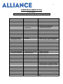
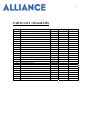
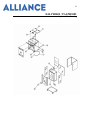
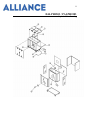
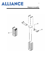
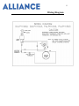
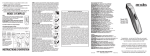
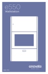
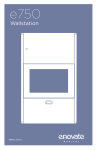
Alliance Products, LLC
Murfreesboro, TN 37129
1-800-522-3973
OPERATIONS MANUAL
DALPH1002, DALPH1503
PELLET HEATERS
PALPH1002, PALPH1503
PLATE HEATERS
Rev. 1-28
2
GENERAL INFORMATION ….………………………………… 3
RECEIVING INSPECTIONS ……………………………………. 3
INSTALLATION ………………………………………………….. 4
ELECTRICAL
…………………………………………………..
5
START-UP ……...………………………………………………….. 6
CLEANING …….………………………………………………….. 7
TROUBLESHOOTING…………………………………………… 8
PARTS LIST / DIAGRAMS …………………………………….. 9
PREVENTIVE MAINTENANCE ..……………………………… 14
WARRANTY …..…………………………………………………... 15
SERVICE AND ASSISTANCE…...……………………………….. 15
RETURN POLICY …………………………………………………. 16
3
GENERAL INFORMATION
The Alliance Pellet / Plate Heaters are available in two capacities. These units are
designed specifically for use with a wide variety of 9” plastic and stainless steel
pellets and plates.
Alliance Pellet / Plate Heaters
Unit No.
No. of Stacks
Capacity per Stack
Total Capacity
DALPH1002 DALPH1503
2
3
43 - 50
43 - 50
86 – 100
129 - 150
Overall Dimensions:
Length
Width
Height
33 3/8"
23 3/4"
42 13/16"
46 11/16"
23 3/4"
42 13/16"
Electrical Requirements
Voltage / Phase
Amperage
Cycle
NEMA Plug Configuration
208V / 1
16
60
6-20P
208V / 1
16
60
6-20P
Shipping Weight (approx.)
270 lbs.
300 lbs.
RECEIVING INSPECTIONS
NOTE: All Alliance units are factory tested for performance prior to shipment.
Upon receipt, the crate should be inspected for visual damage, any damage should be
reported immediately to the carrier.
4
Alliance Damaged Goods Policy
There are two types of damaged merchandise:
A. Visible Damage
B. Concealed Damage
A. Visible Damage – The product being received is visibly damaged.
1. The receiver should refuse the damaged merchandise.
2. The receiver should sign the packing slip “refused merchandise due to
damage” when receiving partial shipment.
3. Contact an Alliance customer service representative and alert them to the
situation.
B. Concealed Damage – When damaged merchandise can not be externally
detected.
1. Save all packing material.
2. Contact an Alliance customer service representative and alert them to the
situation.
3. The receiver must call the carrier to schedule an inspection of the
damaged merchandise.
INSTALLATION
NOTE: The installation instructions are similar for all models of pellet / plate
heaters.
A. Remove all packaging materials from the unit. Remove the protective
cardboard from the inside of the unit.
B. All models are equipped with self-leveling mechanisms that are removable
through the top of the unit so that adjustments can be made to the extension
springs. By adding or removing springs, proper dispensing can be obtained.
5
C. If a spring adjustment is required, proceed as follows. Lift elevating
mechanism assembly up and out of the stainless steel cabinet. Set it on the
floor. Disconnect but do not remove any unnecessary springs from the
elevator carrier and replace mechanism back into the heater.
D. See ELECTRICAL and START-UP sections before plugging unit into
power supply.
ELECTRICAL
Refer to the specifications data on page 3, the serial label, your local code or the
National Electrical Code to be sure the unit is connected to the proper power source.
A protected circuit of the correct voltage and amperage must be available for
connection of the line cord. Place the unit near enough to the electrical outlet so the
power cord is not stretched or strained. Once the unit is properly located, push down
on the two caster brakes to lock them into place. All dish heaters are provided with
a NEMA plug type 6-20P.
WARNING
Every heater is fitted with a grounded power cord and must be connected
to a properly grounded receptacle. Each receptacle must be wired to a
dedicated circuit breaker rated at not more than 20 amps.
WARNING
To prevent electrical shock hazard, the main power switch must be turned
to “off” position and the heater disconnected from the power source
whenever performing service or maintenance.
WARNING
Hazardous voltage inside back of cabinet. Only qualified personnel totally
familiar with electrical circuits, service manual, and service procedures
should open or work inside unit.
6
WARNING
Unit must not be run continually and must be turned off between meals.
Otherwise, unit may shut off automatically requiring service reset.
Warranty may be voided if used improperly.
START-UP
A. Overview
These units are designed to heat plastic or stainless steel pellets or plates. The fan
motor, heating element, and power indicator light will come on once the unit is
turned on. There is a power indicator light to let the operator know the power is
on.
The fan motor will begin to circulate the heated air in and around the plates in a
convection process that promotes a quick and even heat absorption by the pellets.
Once the air inside the cabinet has reached the desired and preset temperature, the
thermostat will continue to maintain this temperature by regulating the power to
the heating element. The fan motor will run as long as the unit is energized.
B. Loading
Load carrier shelf by carefully stacking the pellets / plates in each cavity. Always
keep the load leveled on the shelf or it could bind.
C. Power
Set the power switch to the “ON” position. The power switch will light up when
the unit is on.
Keep the cover closed completely to insure proper and efficient heating.
Depending on the stack size, and the pellet / plate material, the heating time will
vary. The heater should always be turned on 60 to 90 minutes before dispensing.
D. Dispensing
7
CAUTION
Operators should always wear gloves or use pellet / plate lifters when dispensing.
After the unit is turned off, the pellets / plates remaining inside the unit will remain hot
for some time.
CLEANING
CAUTION
Make sure unit is unplugged and cool before attempting to clean.
The following procedures should be followed during the regular cleaning routine
on all of the pellet heaters.
1. Turn the unit off, disconnect the plug from the outlet, and allow the cabinet to
cool. Remove plug by pulling it straight out. Never pull on cord.
2. Pull the elevator mechanisms up and out, place them on a work surface. You
can wipe down the mechanisms with a damp cloth to clean them.
3. Clean out any debris inside the cabinet and wipe the cabinet down with a
damp cloth.
4. Place the elevator mechanisms back inside the cabinet and clean the outside of
the cabinet with a mild, non-abrasive soap or detergent in a warm water
solution. A commercial stainless steel cleaner can also be used for this
procedure.
NOTE: Do not use abrasives, harsh chemicals, or chlorine products for cleaning.
WARNING
Do not steam or pressure clean or hose down the cabinet. This could
damage the equipment and possibly cause an electrical shock to the
operator.
WARNING
Repairs should be done by qualified service personnel only.
8
TROUBLESHOOTING
CAUTION
Thermostat adjustment should only be made only by qualified personnel.
Complaint
Problem
A. Unit does not heat but
fan operates.
1. Open high limit thermostat. 1A. Push reset button.
1B. Check for causes before restarting
equipment.
1C. Replace hi-limit thermostat.
2. Loose wiring.
2. Check and secure wiring.
3. Defective heating element. 3. Replace heating element.
B. Unit heats, but fan does
not blow.
1. Defective motor.
1. Replace motor.
2. Jammed or loose fan blade. 2. Replace or tighten blade.
3. Loose wiring.
3. Determine fault and correct.
C. Unit does not operate
and light does not come
on.
1. No power.
2. Bad power switch.
3. Loose wiring.
Solution
1. Make sure plug is connected and switch
is ON. Check for power to receptacle.
2. Replace power switch.
3. Check and secure wiring.
D. Pellet / plate temperature 1. Thermostat set too low.
1. Readjust thermostat.
Is too low, fan operating. 2. Jammed or loose fan blade. 2. Replace or tighten blade.
3. Cover is open.
3. Close cover.
E. Pellet / plate temperature
Is too high, fan operating.
1. Thermostat is set too high.
2. Closed thermostat.
3. Closed high limit switch.
F. Cover is loose.
1. Hinge screws are missing or 1. Replace or tighten screws.
loose.
G. Dispenser binds.
1. Improper springs.
2. Debris on guide rods.
H. Cabinet does not roll easy. 1. Debris on wheel or axle.
2. No lubrication.
1. Readjust thermostat.
2. Replace thermostat.
3. Replace high limit switch.
1. Depending on contents use correct
number of springs, Make sure identical
number and size of springs are on each
elevator.
2. Clean off debris.
1. Clean out debris.
2. Lubricate axles with load bearing grease.
Lubricate swivel bearings with 30-weight
oil.
9
PARTS LIST / DIAGRAMS
ITEM NO.
1
2
3
4
5
6
7
8
9
10
11
12
13
14
15
16
17
18
19
20
DESCRIPTION
Lid Assembly – End
Lid Assembly – Center
Hinge
Switch Guard
Lid Handle
Push / Pull Handle
Cord - 10 ft. Length
Plug - NEMA 6-20 Straight Blade
On / Off Switch
Motor - 208 / 230V, 60hz 1ph. 3200 rpm
For DALPH1002 and DALPH1503 Models:
Thermostat – Adj. - 250 deg. – 290 deg F
For PALPH1002 and PALPH1503 Models:
Thermostat – Adj. - 135 deg. – 170 deg F
Thermostat – Hi-limit
Heating Element - 208V
Fan Blade - 5/16" Bore
Caster - 5" Swivel
Caster - 5" Swivel w/ Brake
Dispenser Spring
Dispenser Bushing
Dispenser Assembly
Corner Bumpers
PART NO.
015A00101
015A00102
50681-01
50907-01
052P00108
015A00301
--017P00101
030P00109
012P00101
--032P00305
--032P00307
032P00306
015P00104
013P00103
011P00215
011P00216
063P00103
054P00502
SL50
070P00109
PALPH1002 DALPH1503
DALPH1002 DALPH1503
QTY.
QTY.
2
2
--1
4
6
1
1
2
3
1
1
1
1
1
1
1
1
1
1
----1
1
----1
1
1
1
1
1
1
1
2
2
2
2
20
30
8
12
2
3
4
4
10
DALPH1002 / PALPH1002
Exploded View Drawing
11
DALPH1503 / PALPH1503
Exploded View Drawing
12
Dispenser Assembly
Exploded View Drawing
13
Wiring Diagram
14
PREVENTIVE MAINTENANCE
Casters
1. Check casters for freedom of movement and proper brake operation.
2. Maintain casters free of debris. (mop strings, paper, plastic, hair nets, etc…)
3. Clean or replace as required.
Cord and Plug
1. Inspect plug blades for distortion and replace if any blades are missing, bent
or broken.
2. Inspect cord wiring for integrity at termination points by having qualified
service person remove the back panel from the cabinet. Make sure the cord
sheathing extends into the cabinet interior. If wires are showing on the
outside of the cabinet, remove the unit from use and have repairs made before
turning on power to the unit.
Dispensing Mechanism
1. Periodically check springs for proper dispensing by filling each cavity with
pellets / plates and checking to see that it indexes as they are removed. If
pellets / plates do not index properly, and unit is not overloaded, adjust or
replace springs.
15
WARRANTY
One year on parts – 90 days on labor.
Alliance provides to the original purchaser, only, a warranty for the DALPH1002,
DALPH1503, PALPH1002, AND PALPH1503. This warranty covers products and
parts which prove to be defective in materials or workmanship within one (1) year of
the date of shipment from the ALLIANCE factory. Repair or replacement will be at the
option of ALLIANCE and will be f.o.b. the ALLIANCE factory. Warranty includes
ninety (90) days for labor from date of shipment. Prior written authorization from the
ALLIANCE customer service department is required before any component parts or
equipment can be accepted by ALLIANCE for repair, replacement, or credit under this
warranty. This warranty shall not apply if it is determined by ALLIANCE that
equipment or parts have been used other than in accordance with the operating
instructions, subject to abuse or misuse, damage through no fault of ALLIANCE or its
employees, or altered by someone other than ALLIANCE or its authorized agents. This
warranty is exclusive and in lieu of all other warranties express or implied, or statutory,
including the implied warranties of merchantability and fitness. In no event shall
ALLIANCE be liable for any delay in the performance of this warranty due to causes
beyond its control.
SERVICE AND ASSISTANCE
In Warranty Service – Call the Alliance Customer Service Department at 1-800-5223973. Parts are stocked at the factory and will be provided to a local authorized
service agency.
Out of Warranty Service – Same as above except parts will be billed to the customer
or the service agency as dictated by the customer. Labor will be billed by the agency.
Technical Assistance – Write down the nature of the problem and any symptoms along
with any other information that might prove helpful in solving your problem. Then call
the Alliance Customer Service Department at 1-800-522-3973.
16
Return Policy
No product may be returned to Alliance without Alliance’s prior written approval.
Transportation charges are to be prepaid by the Buyer.
Returned goods are subject to Alliance’s inspection and acceptance. Alliance may, at
its discretion, replace any or all returned items within a reasonable time after Alliance
determines that the returned goods are not in accordance herewith: and in such event
Alliance shall not be liable for any damage arising from the defective delivery or delay
caused thereby. When expressly authorized by Alliance in writing, unused products
may be returned to Alliance subject to service handling, restocking and rebuilding
charges to “as new” condition.