1
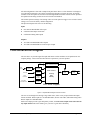
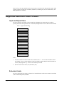
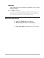
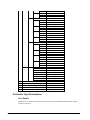
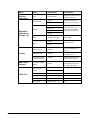
Cobalt Digital Incorporated 9321 HD/SD Audio Embedder Owner’s Manual 9321-UM Version: 0.5 9321 • HD/SD Audio Embedder User Manual • • • • • Cobalt Part Number: 9321-UM Document Version: 0.5.0 Printed in the United States. Last Author: MB Printing Date: 12/18/07 10:19 AM The information contained in this User Manual is subject to change without notice or obligation. Copyright © 2007 Cobalt Digital Incorporated. All rights reserved. Contents of this publication may not be reproduced in any form without the written permission of Cobalt Digital Incorporated. Reproduction or reverse engineering of copyrighted software is prohibited. Notice The material in this manual is furnished for informational use only. It is subject to change without notice and should not be construed as a commitment by Cobalt Digital Incorporated. Cobalt Digital Incorporated assumes no responsibility or liability for errors or inaccuracies that may appear in this manual. Trademarks Page 2 of 23 • is a registered trademark of Ross Video Limited. • • “Cobalt Digital” is a registered trademark of Cobalt Digital Incorporated All other product names and any registered and unregistered trademarks mentioned in this manual are used for identification purposes only and remain the exclusive property of their respective owners. CDI-9321 User Manual • (V 0.5) Important Regulatory and Safety Notices Before using this product and any associated equipment, refer to the “Important Safety Instructions” listed below so as to avoid personnel injury and to prevent product damage. Products may require specific equipment, and /or installation procedures be carried out to satisfy certain regulatory compliance requirements. Notices have been included in this publication to call attention to these specific requirements. Symbol Meanings This symbol on the equipment refers you to important operating and maintenance (servicing) instructions within the Product Manual Documentation. Failure to heed this information may present a major risk of damage or injury to persons or equipment. The symbol with the word “Warning” within the equipment manual indicates a potentially hazardous situation, which if not avoided, could result in death or serious injury. Warning The symbol with the word “Caution” within the equipment manual indicates a potentially hazardous situation, which if not avoided, may result in minor or moderate injury. It may also be used to alert against unsafe practices. Caution The symbol with the word “Notice” within the equipment manual indicates a situation, which if not avoided, may result in major or minor equipment damage or a situation which could place the equipment in a non-compliant operating state. Notice This symbol is used to alert the user that an electrical or electronic device or assembly is susceptible to damage from an ESD event. ESD Susceptibility Important Safety Instructions Caution This product is intended to be a component product of the openGear frame. Refer to the openGear frame User Manual for important safety instructions regarding the proper installation and safe operation of the frame as well as it’s component products. Warning Certain parts of this equipment namely the power supply area still present a safety hazard, with the power switch in the OFF position. To avoid electrical shock, disconnect all A/C power cords from the chassis' rear appliance connectors before servicing this area. Warning Service barriers within this product are intended to protect the operator and service personnel from hazardous voltages. For continued safety, replace all barriers after any servicing. This product contains safety critical parts, which if incorrectly replaced may present a risk of fire or electrical shock. Components contained within the product’s power supplies and power supply area, are not intended to be customer serviced and should be returned to the factory for repair. To reduce the risk of fire, replacement fuses must be the same type and rating. Only use attachments/accessories specified by the manufacturer. CDI-9321 User Manual • (V 0.5) Page 3 of 23 Environmental Information The equipment that you purchased required the extraction and use of natural resources for its production. It may contain hazardous substances that could impact health and the environment. To avoid the potential release of those substances into the environment and to diminish the need for the extraction of natural resources, Cobalt Digital encourages you to use the appropriate take-back systems. These systems will reuse or recycle most of the materials from your end-of-life equipment in an environmentally friendly and health conscious manner. The crossed-out wheeled bin symbol invites you to use these systems. If you need more information on the collection, reuse, and recycling systems, please contact your local or regional waste administration. You can also contact Cobalt Digital for more information on the environmental performances of our products. Page 4 of 23 CDI-9321 User Manual • (V 0.5) Contents Introduction 6 In This Chapter...........................................................................................................................6 A Word of Thanks......................................................................................................................6 Overview....................................................................................................................................6 Functional Block Diagram .........................................................................................................7 Supported Audio and Video Formats .........................................................................................8 Input and Output Video ...............................................................................................8 Embedded Audio .........................................................................................................8 Analog Audio...............................................................................................................9 Discrete AES Audio Input ...........................................................................................9 Documentation Terms ................................................................................................................9 Installation and Setup 10 In This Chapter.........................................................................................................................10 Static Discharge .......................................................................................................................10 Unpacking ................................................................................................................................10 Rear Module Installation (Optional) ........................................................................................11 Board Installation .....................................................................................................................12 Cable Connections....................................................................................................................12 Card Control and Status ...........................................................................................................13 Card Status.................................................................................................................13 Menu Navigation .......................................................................................................13 Menu Structure...........................................................................................................13 Parameter Type Descriptions .....................................................................................14 Factory Default Settings.............................................................................................16 Remote Control 17 In This Chapter.........................................................................................................................17 DashBoard Control System Software.......................................................................................17 Service Information 19 In This Chapter.........................................................................................................................19 Troubleshooting Checklist .......................................................................................................19 Warranty and Repair Policy .....................................................................................................19 Ordering Information 21 9321 and Related Products.......................................................................................................21 CDI-9321 User Manual • (V 0.5) Page 5 of 23 Introduction In This Chapter This chapter includes the following sections: • A Word of Thanks • Overview • Functional Block Diagram • Features • Documentation Terms A Word of Thanks Congratulations on choosing the openGear 9321 HD/SD Audio Embedder. The 9321 is part of a full line of modular conversion gear for broadcast TV environments. The Cobalt Digital openGear line includes video decoders and encoders, audio embeders and de-embeders, distribution amplifiers, format converters, and much more. Cobalt openGear modular conversion gear will meet your signal conversion needs now and well into the future. Should you have questions pertaining to the installation or operation of your 9321, please contact us at the numbers listed on the back cover of this manual. We are happy to help with any questions regarding this or any other openGear card. Overview The 9321 is a high quality audio embedder capable of embedding audio signals into HD or SD SDI signals. It also gives as outputs, two re-clocked copies of the input. The 9321 can best be thought of as having an audio router on the card. On the input side of the router are the up to 16 channels of embedded AES in the input video, the up to 16 channels (8 pairs) of discrete AES input, up to 8 channels of differential analog audio input. On the output side are the up to 16 channels of embedded AES audio. The router acts as a full audio cross point: each of the 16 output embedded channels can receive signal from any one of the 40 (16 embedded AES, 16 discrete AES, 8 Analog) input channels. Each output also allows gain adjustment and optional polarity inversion. Audio rates are always 48kHz nominally but discrete AES inputs pass through sample rate converters to align them with the output timing. Analog audio is differential input and sampled at 48 kHz with 0 dbFS digital equivalent to +24 dBu analog. The product also provides full color processing control of the output video, with separate controls for Gain, Lift, Saturation and Color Phase. Page 6 of 23 CDI-9321 User Manual • (V 0.5) All card configuration is done with a simple front panel menu. There is a four character text display to view and control parameters, and a toggle switch and two buttons to navigate the menu. All settings available on the front panel can also be accessed through Dashboard remote control software provided the openGear frame being used has an 8310-N network card installed. The card has persistent storage of all settings. There is a menu option to trigger a save or load of stored settings, or to restore the factory default configuration. The input and outputs of the 9321 are the following: Input: One dual-rate HD/SD-SDI video input 8 dedicated AES input connections 8 differential analog audio inputs Outputs: Two dual-rate HD/SD-SDI video outputs Two dual-rate HD/SD-SDI re-clocked copies of input Functional Block Diagram The 9321 has a very flexible signal flow path and feature set that combines several products into one compact package. This section describes the basic operation of your 9321 product. Video HD/SD SDI Input EQ and Deserialize Video Proc: Gain, Lift, Saturation, Phase Audio De-embed Audio Control: 8 channels Video Diff. Analog Audio A/D 8 pairs 16 channels AES Decode and SRC From AES or Embedded Audio Dolby E Decode and SRC Audio Embed Routing Gain Polarity Serializer and Cable Driver 9321 Block Diagram Figure 1. Simplified Block Diagram of 9321 Functions The 9321 is best thought of as having a large audio router, with a variety of input format and output formats available. Router inputs are de-embedded audio, discrete AES audio, differential analog audio. Router outputs are embedded audio. Each router output provides a gain and polarity control, and each router output can be sourced from any input channel. This router feature gives your 9321 a great deal of flexibility. CDI-9321 User Manual • (V 0.5) Page 7 of 23 There is also a video proc module to allow any necessary corrections to the inbound video signal. It has separate controls for Luma gain (Y channel), Saturation (C channel gain), Lift (Y channel offset), and Phase adjustment (C channel). Supported Audio and Video Formats Input and Output Video The 9321 supports a wide range of video formats for embedding. The output video rate is always precisely the same as the input video rate. Video delay through the device is less than one microsecond. Table 1. Supported Embedding Video standard 1080 sF 23.98 1080 p 23.98 1080 sF 24 1080 p 24 1080 i 25 1080 p 25 1080 i 29.97 1080 p 29.97 1080 i 30 1080 p 30 720 p23.98 720 p24 720 p 25 720 p 29.97 720 p 30 720 p 50 720 p 59.94 720 p 60 486 i 29.97 575 i 25 Notes: 1. All rates translated to effective frame rates, interlaced rates “ i ” are two times the number shown. For example, i 29.97 is 59.94 fields per second (two fields per frame thus the interlaced frame rate is 29.97); but progressive “ p ” 29.97 is 29.97 frames per second. 2. SD active line rates are PAL (575) and NTSC (486). Embedded Audio The 9321 supports all four groups (16 channels) of embedded audio at full 24 bit resolution in both SD (with extended data packets) and HD. Page 8 of 23 CDI-9321 User Manual • (V 0.5) Analog Audio The 9321 supports 8 channels differential analog audio. The analog audio is encoded in such a way as to make +24 dBu (analog) equivalent to 0 dBFS (digital). Analog audio conversion can be disabled to reduce power consumption. Discrete AES Audio Input The 9321 can accept 16 channels (8 pairs) of discrete AES audio on 75 ohm BNC connections. The AES must have a nominal rate of approximately 48 kHz. Sample rate conversion is employed to account for minor clock rate differences in the AES stream and the input video stream. However, the card does not support AES input at 32 kHz, 44.1 kHz, 96 kHz or 192 kHz rates. Documentation Terms The following terms are used throughout this guide: • “Frame” refers to the 8310 frame that houses the 9321 card. • “Operator” and “User” both refer to the person who uses the 9321. • “Board” and “Card” all refer to the 9321 card itself, including all components and switches. • “System” and “Video system” refers to the mix of interconnected production and terminal equipment in which the 9321 operates. CDI-9321 User Manual • (V 0.5) Page 9 of 23 Installation and Setup In This Chapter This chapter includes the following sections: • Static Discharge • Unpacking • Rear Module Installation (Optional) • Board Installation • BNC Connections • Menu Structure • Factory Defaults Static Discharge Whenever handling the card and other related equipment, please observe all static discharge precautions as described in the following note: Static discharge can cause serious damage to sensitive semiconductor devices. Avoid handling circuit boards in high static environments such as carpeted areas, and when wearing synthetic fiber clothing. Always exercise proper grounding precautions when working on circuit boards and related equipment. ESD Susceptibility Unpacking Unpack each card you received from the shipping container, and check the contents against the packing list to ensure that all items are included. If any items are missing or damaged, contact your sales representative or Cobalt Digital directly. Page 10 of 23 CDI-9321 User Manual • (V 0.5) Rear Module Installation (Optional) If you are installing the card in a 8310-C-BNC or 8310-BNC frame (one with a 100 BNC rear module installed across the entire back plane), skip this section. If you are installing the card into a slot with no rear module, you should have ordered and received a 8310-RM-10 Rear Module with your card. You will need to install it in your 8310 frame before you can connect cables. Use the following steps to install the 8310-RM-10 in an 8310 openGear frame: 1. Refer to the openGear 8310 frame User Manual, to ensure that the frame is properly installed according to instructions. 2. On the rear of the 8310, locate the card frame slot. 3. As shown in Figure 2, seat the bottom of the 8310-RM-10 in the seating slot at the base of the frame’s back plane. Figure 2. Rear Module Installation 4. Align the top hole of the 8310-RM-10 with the screw hole on the top edge of the 8310 back plane. 5. Using a Phillips driver and the supplied screw, fasten the 8310-RM-10 panel to the 8310 back plane. Do not over tighten. This completes the procedure for installing the 8310-RM-10 in an 8310 openGear frame. CDI-9321 User Manual • (V 0.5) Page 11 of 23 Board Installation Use the following steps to install the card in the openGear 8310 frame: 1. Warning Refer to the User Manual of the openGear 8310 frame to ensure that the frame is properly installed according to instructions. Heat and power distribution requirements within a frame may dictate specific slot placement of cards. Cards with many heat-producing components should be arranged to avoid areas of excess heat build-up, particularly in frames using convection cooling. 2. After selecting the desired frame installation slot, hold the card by the edges and carefully align the card edges with the slots in the frame. Then, fully insert the card into the frame until the rear connection plugs are properly seated on the midplane and rear modules. This completes the procedure for installing the card in the openGear 8310 frame. Cable Connections This section provides instructions for connecting cables to the installed BNC rear modules on the 8310 series frame backplane. Connect the input and output cables according to the following diagram. The input is internally terminated with 75 Ohms. It is not necessary to terminate unused outputs. HD/SD-SDI Input 1 2 Not Connected Re-clocked Output 1 3 4 Re-clocked Output 2 AES IN 1 5 6 AES IN 2 AES IN 3 7 8 AES IN 4 HD/SD SDI Output 1 9 10 HD/SD SDI Output 2 Figure 3. BNC Designations for the Card Rear Module 8310-RM-10 or 8310-RM-100 In the near future Cobalt Digital Inc will release a series of rear modules that allow access to the full IO capabilities of the card. Page 12 of 23 CDI-9321 User Manual • (V 0.5) Card Control and Status Card Status The card indicates the status of the input signal with the four blue LEDs labled with the different supported formats (1080, 720, 625, 525). When the card has locked to a particular input format, that LED will be illuminated. When the card has not locked to a particular video format, the card will search all possible formats, and the lights will cycle rapidly. Menu Navigation The card can be configured from a menu system built in to the front card edge. This provides an intuitive and easy to use method for exploring and using the features of the card. The menu is navigated by using the toggle switch and the two push buttons. The lower button is the “Enter” button to enter a submenu, and the upper button is the “Exit” button to exit a submenu. Moving the toggle switch up or down moves up or down in menu choices, and pressing the buttons moves in or out of sub menus. The menu LEDs will illuminate from top to bottom to indicate increasing depth in the menu. Menu Structure The entire 9321 menu looks like this: MENU STRUCTURE Proc Enbl Gain Lift Sat Phas Aud Embd Grp1 Enbl Ch01 Src Gain Pol Ch02 Src Gain Pol Ch03 Src Gain Pol Src Ch04 Gain Pol Grp2 Enbl Ch05 Src Gain Pol Ch06 Src Gain Pol Ch07 Src Gain CDI-9321 User Manual • (V 0.5) Parameter Type Proc Enable Proc Gain Proc Lift Proc Sat Proc Phase Embedded Group Enable Output Source Output Gain Output Polarity Output Source Output Gain Output Polarity Output Source Output Gain Output Polarity Output Source Output Gain Output Polarity Embedded Group Enable Output Source Output Gain Output Polarity Output Source Output Gain Output Polarity Output Source Output Gain Page 13 of 23 Ch08 Grp3 Enbl Ch09 Ch10 Ch11 Ch12 Grp4 Enbl Ch13 Ch14 Ch15 Ch16 AES Disp Prst SBYP Pol Src Gain Pol Src Gain Pol Src Gain Pol Src Gain Pol Src Gain Pol Src Gain Pol Src Gain Pol Src Gain Pol Src Gain Pol AES1 AES2 AES3 AES4 AES5 AES6 AES7 AES8 H/V BRGT Save Load Fact Output Polarity Output Source Output Gain Output Polarity Embedded Group Enable Output Source Output Gain Output Polarity Output Source Output Gain Output Polarity Output Source Output Gain Output Polarity Output Source Output Gain Output Polarity Embedded Group Enable Output Source Output Gain Output Polarity Output Source Output Gain Output Polarity Output Source Output Gain Output Polarity Output Source Output Gain Output Polarity AES SRC Bypass AES SRC Bypass AES SRC Bypass AES SRC Bypass AES SRC Bypass AES SRC Bypass AES SRC Bypass AES SRC Bypass Display Orientation Display Brightness Save Settings Load Settings Restore Factory Settings Parameter Type Descriptions Proc Enable Enables the Proc module. You can keep all the proc settings, and enable/disable the module without having to reset the set Page 14 of 23 CDI-9321 User Manual • (V 0.5) Proc Gain This is Luma (Y channel) gain, expressed as a percentage. It ranges from 0.0% to 200.0% in 0.1% steps. Proc Lift This is Luma (Y channel) offset, expressed as an actual video value ranging from -1024 to 1024. If set to 0 no change is made. If set to 1024 absolute black (value 004) becomes absolute white (value 3FB). If set to –1024, absolute white becomes absolute black. Proc Saturation This is Chroma (C channel) gain, expressed as a percentage. It ranges from 0.0% to 200.0% in 0.1% steps. Proc Phase This is Chroma (C channel) phase adjustment, expressed in degrees, ranging from –360 to +360 in steps of one degree. Embedded Group Enable Enables or disables the embedding of a particular embedded audio group. Disabling a group preserves the settings of the channels belonging to that group. Output Source Because the cards audio system functions like a router, each output can be sourced from any input channel. This parameter let’s you choose from the many different sources. Here is an explanation of the different source names: Source Name Description EmXX Input embedded audio channel XX (1 through 16) AnX Analog Audio channel X (1 through 8) AeXX Discrete AES channel XX (1 through 16) Output Gain The gain of each output is adjustable from +30 dB to –100 dB in 0.1 dB steps. After –100 dB gain is set to –Inf, which means that output is present, but muted. Output Polarity If set to “Norm” output polarity is the same as input polarity, if set to “Inv” the output polarity is inverted. This can be used to correct polarity errors in the input signals fed to the card. AES SRC Bypass Turn on to Bypass Sample Rate Conversion for AES audio inputs. Each input can be bypassed individually from the other AES inputs. Display Orientation This parameter lets you change the orientation of the display. “Vert” makes the characters look correct when the cards are mounted in a 2 RU frame like the 8310. “Horz” makes the characters look right in a horizontal frame. CDI-9321 User Manual • (V 0.5) Page 15 of 23 Display Brightness This parameter allows you to set the standard output brightness of the menu display. It is a percentage of maximum brightness. Save Settings In this parameter, move the toggle switch up to save the settings to the card persistent storage. Load Settings In this parameter, move the toggle switch up to load the saved settings and make them active. Restore Factory Settings In this parameter, move the toggle switch up to make the factory default settings active, and make the stored settings equal to the factory settings. Factory Default Settings The factory default settings are as follows 1) The proc module is enabled, but all parameters are set to not change the video 2) Discrete AES inputs 1-16 are mapped to embedded audio outputs 1-16. 3) Audio gain is set to 0dB and polarity is set to normal on all channels. Page 16 of 23 CDI-9321 User Manual • (V 0.5) Remote Control In This Chapter This section provides a detailed explanation on using remote control functions with your card. DashBoard Control System Software The DashBoard Control System enables you to monitor and control openGearTM frames and controller cards from a computer. The DashBoard software and manual can be downloaded from the Cobalt Digital Inc. website. Using the Menus You must first install the DashBoard Control System software on your computer. Refer to the DashBoard User Manual for software installation procedures and for using the DashBoard interface. The Menu System The following table and sections describe the menus, items, and parameters available from the DashBoard Control System software for the card. Table 3. DashBoard Menus Menu Item Parameters Product CDI-9061 Manufacturer Cobalt Digital Inc. Software Release Number # Description Software Build Date Card Info (Read-only) CDI-9321 User Manual • (V 0.5) Software Build Time +12 V Power Rail #.## W Positive Supply Voltage -7.5 Power Rail #.## W Negative Supply Voltage Video Input Standard Detected Video Standard on SDI Input Reference Standard Detected Standard of Ref. Page 17 of 23 Menu Card Info (Read-only) Item Parameters SSN ############ Group Enable Enable Disable Embedded 1-16 Source Embedded Audio Group (Groups 1-4) AES 1-16 Analog 1-8 Description Displays the Silicon Serial Number of the card. Enables or disables the entire group of 4 channels. Chooses the source for the embedded audio. The source for each channel can be chosen separately. Silence Gain Range (-400) - 400 Gain applied to embedded audio output. Normal Inverts the phase of the embedded audio. Phase Invert Presets Audio Input Controls Video Proc Page 18 of 23 Parameter Save Confirm Saves the parameters as preset. Parameter Load Confirm Loads paramaters previously saved. Restart Parameters to Factory Default Confirm Will load factory presets and overwrite the save. AES Pair 1-8 SRC Bypass Off/On Turn on to Bypass Sample Rate Conversion for AES audio inputs. Proc Controls Enable On Enables/Disables Proc Video Gain Range 0-2000 Contrast Video Lift Range (-999) – 999 Brightness Color Gain Range 0-2000 Saturation Color Phase Range (–360) - 360 Tint Off CDI-9321 User Manual • (V 0.5) Service Information In This Chapter This chapter includes the following sections: • Troubleshooting Checklist • Warranty and Repair Policy Troubleshooting Checklist Routine maintenance to this openGear product is not required. In the event of problems with your card, the following basic troubleshooting checklist may help identify the source of the problem. If the module still does not appear to be working properly after checking all possible causes, please contact your openGear products distributor, or the Technical Support department at the numbers listed under the “Contact Us” section at the end of this manual. 1. Visual Review Performing a quick visual check may reveal many problems, such as connectors not properly seated or loose cables. Check the module, the frame, and any associated peripheral equipment for signs of trouble. 2. Power Check Check the power indicator LED on the distribution frame front panel for the presence of power. If the power LED is not illuminated, verify that the power cable is connected to a power source and that power is available at the power main. Confirm that the power supplies are fully seated in their slots. If the power LED is still not illuminated, replace the power supply with one that is verified to work. 3. Reseat the Card in the Frame Eject the card and reinsert it in the frame. 4. Check Control Settings Refer to the Installation and Operation sections of the manual and verify all user-adjustable component settings. 5. Input Signal Status Verify that source equipment is operating correctly and that a valid signal is being supplied. 6. Output Signal Path Verify that destination equipment is operating correctly and receiving a valid signal. 7. Module Exchange Exchanging a suspect module with a module that is known to be working correctly is an efficient method for localizing problems to individual modules. Warranty and Repair Policy The openGear card is warranted to be free of any defect with respect to performance, quality, reliability, and workmanship for a period of FIVE (5) years from the date of shipment from our factory. CDI-9321 User Manual • (V 0.5) Page 19 of 23 In the event that your Cobalt Digital Incorporated card proves to be defective in any way during this warranty period, Cobalt Digital Incorporated reserves the right to repair or replace this piece of equipment with a unit of equal or superior performance characteristics. Should you find that this openGear card has failed after your warranty period has expired, we will repair your defective product should suitable replacement components be available. You, the owner, will bear any labor and/or part costs incurred in the repair or refurbishment of said equipment beyond the FIVE (5) year warranty period. In no event shall Cobalt Digital Incorporated be liable for direct, indirect, special, incidental, or consequential damages (including loss of profits) incurred by the use of this product. Implied warranties are expressly limited to the duration of this warranty. This openGear card User Manual provides all pertinent information for the safe installation and operation of your Cobalt Digital Incorporated Product. Cobalt Digital Incorporated policy dictates that all repairs to the openGear card are to be conducted only by an authorized Cobalt Digital Incorporated factory representative. Therefore, any unauthorized attempt to repair this product, by anyone other than an authorized Cobalt Digital Incorporated factory representative, will automatically void the warranty. Please contact Cobalt Digital Incorporated Technical Support for more information. In Case of Problems Should any problem arise with your openGear card, please contact the Cobalt Digital Incorporated Technical Support Department. (Contact information is supplied at the end of this publication.) A Return Material Authorization number (RMA) will be issued to you, as well as specific shipping instructions, should you wish our factory to repair your openGear card. If required, a temporary replacement module will be made available at a nominal charge. Any shipping costs incurred will be the responsibility of you, the customer. All products shipped to you from Cobalt Digital Incorporated will be shipped collect. The Cobalt Digital Incorporated Technical Support Department will continue to provide advice on any product manufactured by Cobalt Digital Incorporated, beyond the warranty period without charge, for the life of the equipment. Page 20 of 23 CDI-9321 User Manual • (V 0.5) Ordering Information 9321 and Related Products Your 9321 HD/SD Audio Embedder is a part of the openGear family of products. Cobalt Digital offers a full line of openGear terminal equipment including distribution, conversion, monitoring, synchronizers, encoders, decoders, embedders, and de-embedders, as well as analog audio and video products. Standard Equipment • 9321 HD/SD Audio Embedder • 9321-UM HD/SD Audio Embedder Optional Equipment • 9321-UM HD/SD Audio Embedder (additional User Manual) • 8310-RM-10 openGear Rear Module compatible with 9321 (10 BNC connector) • 8310-C Digital Products Frame and Power Supply with Cooling Fans (2RU, holds 10 cards) • 8310-C-BNC Digital Products Frame and Power Supply with fixed 100-BNC Rear Module and Cooling Fans. (2RU, holds 10 cards) • MFC-8310-N Network Controller Card (Additional) CDI-9321 User Manual • (V 0.5) Page 21 of 23 Notes: Page 22 of 23 CDI-9321 User Manual • (V 0.5) Contact Us Contact our friendly and professional support representatives for the following: • Name and address of your local dealer • Product information and pricing • Technical support • Upcoming trade show information PHONE E-MAIL POSTAL SERVICE General Business Office and Technical Support 217 • 344 • 1243 Fax General Information Technical Support 217 • 344 • 1245 Cobalt Digital Incorporated 2406 East University Avenue Urbana, IL 61802 USA [email protected] [email protected] Visit Us Please visit us at our website for: • Company information • Related products and full product lines • On-line catalog • Trade show information • News • Testimonials http://www.cobaltdigital.com/ CDI-9321 User Manual • (V 0.5) Page 23 of 23