1
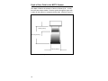
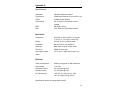
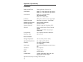
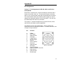
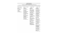
METROLOGIC® INSTRUMENTS, INC. TECH 7® Laser Bar Code Projection Scanner Installation and User’s Guide Copyright © 2006 by Metrologic Instruments, Inc. All rights reserved. No part of this work may be reproduced, transmitted, or stored in any form or by any means without prior written consent, except by reviewer, who may quote brief pas sages in a review, or provided for in the Copyright Act of 1976. Products and brand names mentioned in this document are trademarks of their respective companies. Table of Contents Introduction . . . . . . . . . . . . . . . . . . . . . . . . . . . . . . . . . . . . . . . . . . 1 Unpacking List . . . . . . . . . . . . . . . . . . . . . . . . . . . . . . . . . . . . . . . 1 Scanner Installation . . . . . . . . . . . . . . . . . . . . . . . . . . . . . . . . . . . 2 Configuration to the Host System . . . . . . . . . . . . . . . . . . . . . . . . . 3 Stand Installation . . . . . . . . . . . . . . . . . . . . . . . . . . . . . . . . . . . . . 4 Back Plate Installation . . . . . . . . . . . . . . . . . . . . . . . . . . . . . . . . . . 5 Parts of Scanner . . . . . . . . . . . . . . . . . . . . . . . . . . . . . . . . . . . . . . 6 Visual Indicators . . . . . . . . . . . . . . . . . . . . . . . . . . . . . . . . . . . . . . 7 Labels . . . . . . . . . . . . . . . . . . . . . . . . . . . . . . . . . . . . . . . . . . . . . 11 Depth of Scan Field for the MS770 Scanner . . . . . . . . . . . . . . . . 12 Depth of Field for the MS775 Scanner . . . . . . . . . . . . . . . . . . . . 13 Maintenance . . . . . . . . . . . . . . . . . . . . . . . . . . . . . . . . . . . . . . . . 14 Applications and Protocols . . . . . . . . . . . . . . . . . . . . . . . . . . . . . 14 Appendix A Specifications Mechanical . . . . . . . . . . . . . . . . . . . . . . . . . . . . . . . . . . . . . . 15 Electrical . . . . . . . . . . . . . . . . . . . . . . . . . . . . . . . . . . . . . . . 15 Operational . . . . . . . . . . . . . . . . . . . . . . . . . . . . . . . . . . . . . . 16 Environmental . . . . . . . . . . . . . . . . . . . . . . . . . . . . . . . . . . . 16 Appendix B Pin Assignments . . . . . . . . . . . . . . . . . . . . . . . . . . . . . . . . . . 17 Appendix C Warranty and Disclaimer . . . . . . . . . . . . . . . . . . . . . . . . . . . . 19 Appendix D Notices . . . . . . . . . . . . . . . . . . . . . . . . . . . . . . . . . . . . . . . . . 20 Appendix E Patents . . . . . . . . . . . . . . . . . . . . . . . . . . . . . . . . . . . . . . . . . 22 Index . . . . . . . . . . . . . . . . . . . . . . . . . . . . . . . . . . . . . . . . . . . . . 23 ii Introduction Metrologic's TECH 7® laser bar code projection scanner is encased in an NEMA-12 steel case. The case construction enables the scanner to operate in harsh surroundings, especially industrial environments. Water-resistant, shock-resistant, and rugged, the TECH 7 is also fast, aggressive and reliable. It can register bar codes at a range of 76mm - 254mm (3" - 10") and can autodiscriminate among all common codes. To suit particular applications, two different scan patterns are available: an omnidirectional pattern of 20 interlocking lines (Model MS770); or a 12-line raster pattern (Model MS775). The scanner has a VLD design, a scan speed of up to 2000 lines per second, and uses less than 8 watts of power. Other features include an Application Specific Integrated Circuit (ASIC) and MECCA© (Metrologic Enhanced Code Correcting Algorithm). An Application Specific Integrated Circuit (ASIC) is in the decoding system and virtually eliminates misreads. MECCA© (Metrologic Enhanced Code Correcting Algorithm) enables the TECH 7 scanner to read poorly printed, wrinkled or even torn bar codes on the first pass. Unpacking List The shipping carton, should contain the following: z Installation and User's Guide (MLPN: 2159) z ScanSelect™ Scanner Programming Guide (MLPN: 2186) z TECH 7 Model MS770 with omnidirectional scan pattern or TECH 7 Model MS775 with raster scan pattern z Communication Cable with Power Supply (optional) or Communication Cable (optional) z Back Plate (optional) or Stand (optional) If any item is missing or to order additional items, contact the dealer, distributor or call Metrologic's Customer Service Department at 1-800-ID-METRO or 1-800-436-3876. 1 Scanner Installation To maintain compliance with applicable standards, all circuits con nected to the scanner must meet the requirements for SELV (Safety Extra Low Voltage) according to EN 60950. To avoid potential prob lems, do not power up the scanner until the communication cable is secured to the host. 1. "Power off" the host system. 2. Locate the 19-pin female end of the scanner link cable and find the widest key located above pins L and A. Align this key with the corresponding key on the scanner box's Mil spec connector. While pushing in on the connector, rotate the ring clockwise until it locks into place with a click. 3. Connect the other end of the communication cable to the host device. Note: The following statement is applicable if the optional power adapter available through Metrologic does not power the bar code scanner and the scanner receives power from a host device such as a computer system. Caution: To maintain compliance with standards CSA C22.2 No. 950/UL 1950 and norm EN 60950, the power source must meet applicable performance requirements for a limited power source. If the scanner is powered by the host, skip to Step 5. 4. Check the AC input requirements of the transformer/power supply to make sure the voltage matches an available AC outlet. A socket-outlet must be installed near the equipment and be easily accessible. Plug the transformer into the AC outlet to supply power to the scanner. 5. "Power up" the host system. Note: When the scanner first receives power, the LEDs will flash and then the scanner will beep once. After the scanner performs this startup sequence, the green LED will remain on for a specified time indicating that the laser is on. 2 Configuration to the Host System The scanner is shipped from the factory programmed to a set of default conditions noted in the ScanSelect™ Scanner Programming Guide by an asterisk that appears before the brief definition located next to the bar code. In order for the scanner to communicate with a host system properly, it may need to be programmed. Since each host system is unique, con figure the scanner to match the host system requirements. Configure the scanner by entering the program mode and scanning the appro priate bar codes that appear in the ScanSelect Scanner Programming Guide. (To use ScanSet®, refer to the ScanSet documentation for information on how to configure a scanner.) 1. Connect the scanner to the host system (Refer to the Scanner Connections to the Host section in this guide). 2. Enter program mode by scanning the ENTER/EXIT program mode bar code. The unit will beep three times 3. Scan the appropriate bar code(s) that appear in the ScanSelect Scanner Programming Guide. Reveal only one bar code to the scanner each time. With your hand, cover the bar code not to be scanned. 4. Exit program mode by scanning the ENTER/EXIT program mode bar code again. The new options will be saved and the scanner is ready for normal operation. 3 Stand Installation With the Metrologic stand (Part #45475), the scanner can be posi tioned in one of two directions. The two orientation choices are vertical or horizontal. (Refer to Figure 1) Horizontal Mount Vertical Mount Figure 1: Stand Orientation To install this stand, use the four 6-32 x ½ inch machine screws and two #10 pan head wood screws. 1. Drill two holes into the work surface that are the same size and distance as the holes on the stand base. (Refer to Figure 2) 1.00 in 3.00 in 2. Use the two #10 pan head wood screws to attach the stand to the work surface. 1.50 in Figure 2: Base of Stand 3. To fasten the scanner: z z For a horizontal mount, align the four holes on the back of the scanner with the four clearance holes located on the stand marked with an X in Figure 3. For a vertical mount, align the four holes on the back of the scanner with the four clearance holes located on the stand marked with a Y in Figure 3. X X Y X Y X Y Y X = Holes for Horizontal Mount Y = Holes for Vertical Mount Figure 3: Back View of Stand 4. Fasten the scanner to the stand by inserting the four 6-32 x ½ inch screws into the four holes in the scanner's case. 4 Back Plate Installation With the Metrologic back plate (Part #45473), position the scanner in one of two directions. The two orientation choices are vertical or horizontal. (Refer to Figure 4). To use this stand, use the four 6-32 x ½ inch machine screws and four wood screws to attach the unit to the back plate and work surface. The maximum distance the screws should go into the scanner is a ½ inch. Vertical Mount Horizontal Mount Figure 4: Back Plate Orientation 1. Drill four holes into the work surface that correspond with the holes indicated by an XY in Figure 5. 2. To fasten the scanner to the back plate: z For a horizontal mount, align the four holes on the back of the scanner with the four clearance holes located on the back plate marked with an X in Figure 5. z For a vertical mount, align the four holes on the back of the scanner with the four clearance holes located on the back plate marked with a Y in Figure 5. 3. Fasten the scanner to the back plate by inserting the four 6-32 x ½ inch screws into the four holes in the scanner's case. Fasten the scanner and back plate to the work surface. XY XY Y X Y Y X XY Y X XY X X = Scanner Horizontal Mount Y = Scanner Vertical Mount XY = Back Plate Mounting Figure 5: Back Plate Hole Pattern 5 Parts of Scanner 1 2 3 4 Figure 6: Scanner Parts 1 reen and Red LEDs G When the green LED is on, this indicates that the unit is receiving power and the laser is on. When the red LED flashes on, the scanner has read a bar code successfully. When the red light turns off, communication to the host is complete. 2 peaker S The speaker emits a beep when a bar code has been decoded. 3 Laser Output Window This aperture emits the laser light. 4 6 il spec Connector M The 19-pin male Mil spec connector was designed to connect a communication cable from the scanner to a host device. The communication cable may include a power supply or it may be designed to draw power directly from the host device. The standard TECH 7 has one connector. (When the atrium option is installed, a second connector is installed on the unit to connect the MX001 Industrial Control Interface box.) Visual Indicators There is a red and green LED at the top of the scanner. When the scanner is on, the flashing or stationary activity of the LEDs indicates the status of the scan and scanner. Steady Green When the laser is on, the green LED is also on. This occurs when an object is in the scan field. Steady Green; Red Flash When the scanner successfully reads a bar code, the red LED will flash then beep once. If the red LED does not flash or the scanner does not beep once, then the bar code has not been successfully read. Steady Red and Green After a successful scan, the scanner transmits the data to the host device. When the host is not ready to accept the information, the scanner's red LED will remain on until the data can be transmitted. Alternating Red and Green This indicates the scanner is in program mode. Steady Red This indicates the scanner is in ScanSet mode. No Red or Green LED There are two reasons why the LEDs will not be illumi nated. First, if the scanner is receiving power and the LEDs are not on, then the scanner has remained dormant for a specified time and the laser has turned off. To reacti vate the unit, touch the touch plate. Secondly, if the scanner is not receiving power from the host or trans former, then the LEDs will not turn on. Flashing Red This indicates the scanner has experienced a laser sub system failure. Return the unit for repair at an authorized service center. 7 Signaux Optiques Sur la partie supérieure du scanner se trouvent une diode LED rouge et une diode LED verte. Quand le scanner est sous tension, les diodes rouge et verte clignotantes ou allumées vous informent sur l'état du scanner. Ni la diode rouge, ni la diode verte n'est allumée Il existe deux raisons possibles pour que les diodes ne s'allument pas. Premièrement: si le scanner reçoit de l'énergie sans que les diodes ne s'allument, le scanner est resté sans servir pendant une certaine période et le laser est désactivé. Pour le réactiver, passer un objet devant le palpeur infrarouge. Deuxièmement: quand le scanner ne reçoit de l'énergie ni de l'ordinateur central, ni du transformateur, les diodes restent éteintes. La diode verte reste allumée Quand le laser est en service, la diode verte s'allume également. C'est le cas quand un objet se trouve devant le palpeur. La diode verte reste allumée tant que la temporisation de l'infrarouge dure ou jusqu'à ce que le scanner soit désactivé. La diode verte reste allumée; la diode rouge clignote Après lecture avec succès d'un code à barres par le scanner, la diode rouge se met à clignoter, suivie d'un bip sonore unique. Si la diode rouge ne clignote pas ou quand aucun bip sonore n'est émis, cela sig nifie que le code à barres n'a pas pu être lu avec succès. Les diodes rouges et vertes restent allumées Une fois la lecture effectuée avec succès, le scanner transmet les données à l'ordinateur central. Si ce dernier n'est pas prêt à recevoir les données, la diode rouge du scanner reste allumée jusqu'à ce que les données puissent être transmises. Les diodes rouges et vertes clignotent en alternance Indique que le scanner se trouve en mode de programmation. La diode rouge reste allumée Indique que le scanner se trouve en mode ScanSet. Diode rouge clignotante Indique une panne de laser pendant la lecture. Veuillez envoyer votre appareil chez unconcessionnaire pour réparation. 8 Optische Anzeigen Auf dem Scanner befinden sich eine rote und eine grüne Leuchtdiode. Bei eingeschaltetem Scanner geben Ihnen die blinkenden bzw. feststehenden Leuchtdiodenanzeigen Aufschluß über den Abtast-und Scannerstatus. Weder rote noch grüne Leuchtdiodenanzeige Es gibt zwei mögliche Gründe, weshalb die Leuchtdiodenanzeigen nicht aufleuchten. Erstens: Wenn der Scanner mit Energie versorgt wird und die Leuchtdiodenanzeigen nicht aufleuchten, so ist der Scanner für einen bes timmten Zeitraum untätig geblieben, und der Laser ist abgeschaltet. Zur Reaktivierung der Einheit sollten Sie ein Objekt vor dem Infrarot-Sensor hin- und herbewegen. Zweitens: Wenn der Scanner weder vom Hostrechner noch vom Transformator Energie erhält, so leuchten die Leuchtdiodenanzeigen nicht auf. Feststehende grüne Anzeige Wenn der Laser in Betrieb ist, leuchtet die grüne Leuchtdiodenanzeige ebenfalls auf. Dies ist dann der Fall, wenn sich ein Objekt im Abtastfeld befindet. Die grüne Leuchtdiodenanzeige leuchtet solange auf, bis das Infrarot-Timeout abgelaufen ist, oder bis der Scanner abgeschaltet wird. Feststehende grüne Leuchtanzeige; rote Blinkanzeige Nach erfolgreichem Lesen eines Barcodes durch den Scanner blinkt die rote Leuchtdiodenanzeige auf, gefolgt von einem einmaligen PiepSignal. Blinkt die rote Leuchtdiodenanzeige nicht auf oder sendet der Scanner kein Piep-Signal aus, so konnte der Barcode nicht erfolgreich gelesen werden. Feststehende rote und grüne Leuchtanzeige Nach erfolgreichem Abtasten überträgt der Scanner die Daten an das Hostgerät. Falls das Hostgerät zur Datenannahme nicht bereit ist, leuchtet die rote Leuchtdiodenanzeige des Scanners solange auf, bis die Daten übertragen werden können. Alternierende rote und grüne Leuchtanzeige Zeigt an, daß sich der Scanner im Programmiermodus befindet. Feststehende rote Leuchtanzeige Zeigt an, daß sich der Scanner im ScanSet-Modus befindet. Aufblinkende rote Leuchtanzeige Zeigt an, daß beim Scanner ein Laserausfall vorliegt. Bringen Sie das Gerät zur Reparatur in ein Vertragsservicecenter. 9 Segnali Ottici Sullo scanner si trovano due diodi luminosi: uno rosso e uno verde. Quando lo scanner è inserito, i diodi luminosi, che possono o essere accesi in continuazione o lampeggiare, Vi informano sullo stato della scansione e dell'apparecchio. Né il diodo luminoso rosso né quello verde sono accesi Vi sono due possibili cause se i diodi luminosi non sono accesi. Prima causa: se lo scanner viene alimentato e i diodi luminosi non sono accesi, lo scanner è rimasto disattivato per un determinato periodo e il laser è spento. Per riattivare l'unità dovreste muovere un oggetto davanti al sensore a infrarossi. Seconda causa: se lo scanner non viene alimentato né dal calcolatore host né dal trasformatore, i due diodi luminosi non sono accesi. Il diodo luminoso verde è acceso Quando il laser è inserito, è acceso anche il diodo luminoso verde. Questo si ha quando un oggetto si trova nella zona di scansione. Il diodo luminoso verde è acceso fino al raggiungimento del timeout infrarossi oppure fino allo spegnimento dello scanner. Il diodo luminoso verde è acceso; quello rosso lampeggia Dopo la lettura riuscita di un codice a barre da parte dello scanner il diodo luminoso rosso lampeggia e quindi viene emesso un unico seg nale beep. Se il diodo luminoso rosso non lampeggia oppure lo scanner non emette un segnale beep, ciò significa che la lettura del codice a barre non è riuscita. Sono accesi sia il diodo luminoso rosso che quello verde Dopo la scansione riuscita lo scanner trasmette i dati all'host. Se l'host non è pronto per accettare i dati, il diodo luminoso rosso dello scanner è acceso fino a che i dati possono essere trasmessi. Il diodo luminoso rosso e quello verde sono accesi in alternanza Ciò indica che lo scanner si trova nella modalità di programmazione. Il diodo luminoso rosso è acceso Ciò indica che lo scanner si trova nella modalità ScanSet. Il diodo luminoso rosso lampeggia Ciò indica che lo scanner ha un guasto a livello del laser. Fate riparare l'apparecchio da un centro di assistenza autorizzato. 10 Labels There is one label located inside the window of the scanner noting that this device is a CDRH Class IIa laser product and IEC 825 LASERKLASSE 1. Also, on the scanner is a label located on the back of the unit. This label contains information such as the model number, date of manufacture, serial number, and approvals. The following are samples of the labels located on the unit. Metrologic ® Metrologic Instruments, Inc. Blackwood, New Jersey, USA Contains no user serviceable components. Warranty void if case is opened. Complies with FCC Class A. See manual. This product complies with US DHHS Standard 21 CFR Chapter 1 Subchapter J. Class IIa Laser Product. Avoid long-term viewing of direct laser light. Eviter toute exposition prolongee de la vue au rayonnement laser direct. Appareil laser Classe IIa Manufactured Blackwood, NJ. 11-30V August 1999 Model: IS770-F1 TECH 7™ Barcode Scanner Serial # : XXXXXXXXXX CAUTION: Laser Light when opened. DO NOT STARE INTO BEAM 11 Depth of Scan Field for the MS770 Scanner The depth of field for the scanner is 76mm to 254mm (3.00” - 10.00”) from the laser output window. Pass the symbol through the scan area in order for the scanner to recognize the bar code. (Refer to Figure 7) 76 mm [3.00 in] 254 mm [10.00 in] 152 mm [6.00 in] Figure 7: MS770 Scanner, Front View 12 Depth of Scan Field for the MS775 Scanner The depth of field for the scanner is 76mm to 254mm (3.00” - 10.00”) from the laser output window. Pass the symbol through the scan area in order for the scanner to recognize the bar code. (Refer to Figure 8) 76 mm [3.00 in] 254 mm [10.00 in] 229 mm [9.00 in] Figure 8: MS775 Scanner, Front View 13 Maintenance Smudges and dirt can interfere with the proper scanning of a bar code. Therefore, the output window will need occasional cleaning. 1. Spray glass cleaner onto lint free, nonabrasive cleaning cloth. 2. Gently wipe the output window. Applications and Protocols The model number on each scanner includes the scanner number and communications protocol. Version Identifier 1 15 14 Communication Protocol(s) RS-232, OCIA, Bidirectional RS-232 Light Pen Emulation Appendix A Specifications Application: Industrial Projection Scanner Light Source: Visible Laser Diode 650 ± 5 nm or 670 ± 5 nm CDRH: CLASS IIa laser product Certifications: CE, UL listed for the US and CUL for Canada EMC: EN 60825: Class 1 EMI: FCC, ICES-003 & EN 55022 Class A Mechanical Dimensions: 184 mm(L) x 186 mm (W) x 78 mm (D) [7.25 in (L) x 7.3 in (W) x 3.06 in (D)] Weight: 2.35 kg. (5.19 lbs.) without cable Orientation: May be used in any orientation Mounting: Back plate mount or Vertical stand Top Cover: NEMA-12 steel case Host Cable Length: 1.83 m (6 Ft.) cable with mil spec con nector Electrical Power Consumption: 8 watts, host system or wall transformer Input Voltage: 11-30 VDC Operating Current: 420 mA typical @ 20V Standby Current: 210 mA typical @ 20V DC Transformers: 120V (AC in), 230V (AC in), 240V ( AC in); output 20V @ 750 mA Specifications subject to change without notice 15 Appendix A (Continued) Operational Depth of Scan Field: 76mm to 254 mm (3 in to 10 in) Scan Speed: Model 770: 2000 scan lines per second Model 775: 1200 scan lines per second Scan Pattern: Model 770: Omnidirectional (20 interlocking lines) Model 775: 12-line raster Indicators: LED: green = laser on; red = good read Beeper Operation: Selection of 3 tones for "Good Read" Maintenance Required: Clean window periodically Decode Capability: Autodiscriminates System Interfaces: RS232C; Light Pen Emulation; OCIA Optional: Opto coupled 6 amps US and Canada, 5 amps EEA countries TRIAC output; object sensor input Print Contrast: 35% minimum reflectance difference Roll, Pitch, Yaw: 360°, 60°, 60° Environmental Storage Temperature: -40°C to 60°C (-40°F to 140°F) Operating Temperature: 0°C to 35°C (32°F to 95°F) Humidity: 5% to 95% relative humidity, non-condensing Light Levels: Up to 3200 foot candles - works in direct sun Ventilation: None required Shock: 100g for 1ms ESD: 8 kV IEC 801-2 Contaminants: Protects against dust, falling dirt, and dripping non-corrosive liquid Specifications subject to change without notice. 16 Appendix B Pin Assignments Version "1" Pin Assignments for RS-232, OCIA, and Bi-direc tional RS-232 Each TECH 7 scanner has a 19-pin male Mil spec connector that is located on the side of the unit. To connect the scanner to the host device, use a communication cable with a female Mil spec connector. The communication cable may include a power supply or it may be designed to draw power directly from the host device. This item can be ordered when the scanner is purchased. The Version "1" scanner is designed to be used for RS-232, OCIA, and RS-232 with limited receiving capabilities. The following is a list of pin assignments. The pin numbers are impressed on the male Mil spec connector. For easier reference, refer to Figure 9 for pin locations. Pin Function A B C D E F G H J K L M N P R S R Data RTS Output Signal Ground CTS Input R Data Return RS-232 Output Clock in Clock in Return Clock Out Shield Ground DTR Input Clock Out Return Power to Scanner & 24 VDC Earth Ground Power Ground RS-232 Input A L N M K J H R S G B P U T F C D E Figure 9: Pin Locations 17 Appendix B (Continued) Version "15" Pin Assignments for Light Pen Emulation Each TECH 7 scanner has a 19-pin male Mil spec connector that is located on the side of the unit. To connect the scanner to the host device, use a communication cable with a female Mil spec connector. The communication cable may include a power supply or it may be designed to draw power directly from the host device. This item can be ordered when the scanner is purchased. The Version "15" scanner is designed to be used for Light Pen Emulation communication. The following is a list of pin assignments. The pin numbers are impressed on the male Mil spec connector. For easier reference, refer to Figure 10 for pin locations. Pin A B C D E F G H J K L M N P R S 18 Function R Data Light Pen Data Output Signal Ground Light Pen Source & 5 VDC R Data Return RS-232 Output Clock in Clock in Return Clock Out Shield Ground DTR Input Clock Out Return Power to Scanner & 24 VDC Earth Ground Power Ground RS-232 Input K J L A M N H R S G B P U T F C D E Figure 10: Pin Locations Appendix C Warranty and Disclaimer Limited Warranty The Tech 7 scanners are manufactured by Metrologic at its Blackwood, New Jersey, U.S.A. facility. The Tech 7 scanners have a two (2) year limited warranty from the date of manufacture. Metrologic warrants and represents that all Tech 7 scanners are free of all defects in material, workmanship and design, and have been produced and labeled in compliance with all applicable U.S. Federal, state and local laws, regulations and ordinances pertaining to their production and labeling. This warranty is limited to repair, replacement of Product or refund of Product price at the sole discretion of Metrologic. Faulty equipment must be returned to the Metrologic facility in Blackwood, New Jersey, U.S.A. or Puchheim, Germany. To do this, contact Metrologic's Customer Service/Repair Department to obtain a Returned Material Authorization (RMA) number. In the event that it is determined the equipment failure is covered under this warranty, Metrologic shall, at its sole option, repair the Product or replace the Product with a functionally equivalent unit and return such repaired or replaced Product without charge for service or return freight, whether distributor, dealer/reseller, or retail con sumer, or refund an amount equal to the original purchase price. This limited warranty does not extend to any Product which, in the sole judgement of Metrologic, has been subjected to abuse, misuse, neglect, improper installation, or accident, nor any damage due to use or misuse produced from integration of the Product into any mechanical, electrical or computer system. The warranty is void if the case of Product is opened by anyone other than Metrologic's repair department or authorized repair centers. THIS LIMITED WARRANTY, EXCEPT AS TO TITLE, IS IN LIEU OF ALL OTHER WARRANTIES OR GUARANTEES, EITHER EXPRESS OR IMPLIED, AND SPECIFICALLY EXCLUDES, WITHOUT LIMITATION, WARRANTIES OF MERCHANTABILITY AND FITNESS FOR A PARTIC ULAR PURPOSE UNDER THE UNIFORM COMMERCIAL CODE, OR ARISING OUT OF CUSTOM OR CONDUCT. THE RIGHTS AND REMEDIES PROVIDED HEREIN ARE EXCLUSIVE AND IN LIEU OF ANY OTHER RIGHTS OR REMEDIES. IN NO EVENT SHALL METROLOGIC BE LIABLE FOR ANY INDIRECT OR CONSEQUENTIAL DAMAGES, INCIDENTAL DAMAGES, DAM AGES TO PERSON OR PROPERTY, OR EFFECT ON BUSINESS OR PROPERTY, OR OTHER DAMAGES OR EXPENSES DUE DIRECTLY OR INDIRECTLY TO THE PRODUCT, EXCEPT AS STATED IN THIS WARRANTY. IN NO EVENT SHALL ANY LIABILITY OF METROLOGIC EXCEED THE ACTUAL AMOUNT PAID TO METROLOGIC FOR THE PRODUCT. METROLOGIC RESERVES THE RIGHT TO MAKE ANY CHANGES TO THE PRODUCT DESCRIBED HEREIN. USA Corporate Headquarters 90 Coles Road Blackwood, NJ 08012-4683 Customer Service: 1-800-ID-METRO Tel: 856-228-8100 Fax: 856-228-6673 Europe Metrologic Instruments GmbH Dornierstrasse 2 82178 Puchheim b. Munich, Germany Tel: 49-89-89019-0 Fax: 49-89-89019-200 South America Rua Flórida 1.821, 5° Andar-Brooklin CEP 04571-090, São Paulo-SP, Brasil Outside Brazil: Metrologic South America Tel: 55-11-5505-6568 Fax: 55-11-5505-1681 Inside Brazil: Metrologic do Brasil Ltda Tel: 55-11-5505-2396 Fax: 55-11-5507-2301 Asia Metrologic Asia (PTE) Ltd. 31, Kaki Bukit Road 3 #05-08 Techlink Singapore 417818 Tel:65-842-7155 Fax: 65-842-7166 19 Appendix D Notices This equipment has been tested and found to comply with limits for a Class A digital device, pursuant to Part 15 of the FCC Rules. These limits are designed to provide reasonable protection against harmful interference when the equipment is operated in a commercial environment. This equipment generates, uses and can radiate radio frequency energy and, if not installed and used in accordance with the instruction manual, may cause harmful interference to radio communications. Operation of this equipment in a residential area is likely to cause harmful interference, in which case the user will be required to correct the interference at his own expense. Any unauthorized changes or modifica tions to this equipment could void the users authority to operate this device. Notice This Class A digital apparatus complies with Canadian ICES-003. Caution Use of controls or adjustments or performance of procedures other than those specified herein may result in hazardous laser light. Under no circumstances should the customer attempt to service the laser scanner. Never attempt to look at the laser beam, even if the scanner appears to be nonfunc tional. Never open the scanner in an attempt to look into the device. Doing so could result in haz ardous laser light exposure. The use of optical instruments with the laser equipment will increase eye hazard. Remarque Cet appareil numérique de la classe A est conformé a la norme NMB-003 du Canada. Attention L'emploi de commandes, réglages ou procédés autres que ceux décrits ici peut entraîner de graves irradiations. Le client ne doit en aucun cas essayer d'entretenir lui-même le scanner ou le laser. Ne regardez jamais directement le rayon laser, même si vous croyez que le scanner est inactif. N'ouvrez jamais le scanner pour regarder dans l'appareil. Ce faisant, vous vous exposez à une ray onnement laser mortel. L'emploi d'appareils optiques avec cet équipement laser a-ugmente le risque d'endommagement de la vision. Achtung Die Verwendung anderer als der hierin beschriebenen Steuerungen, Einstellungen oder Verfahren kann eine lebensgefährliche Laserstrahlung hervorrufen. Der Kunde sollte unter keinen Umständen versuchen, den Laser-Scanner selbst zu warten. Sehen Sie niemals in den Laserstrahl, selbst wenn Sie glauben, daß der Scanner nicht aktiv ist. Öffnen Sie niemals den Scanner, um in das Gerät hineinzusehen. Wenn Sie dies tun, können Sie sich einer lebensgefährlichen Laserstrahlung aus setzen. Der Einsatz optischer Geräte mit dieser Laserausrüstung erhöht das Risiko einer Sehschädigung. Attenzione L’utilizzo di sistemi di controllo, di regolazioni o di procedimenti diversi da quelli decritti nel presente Manuale può provocare dei raggi laser pericolosi per la vita. Il cliente non deve assolutamente tentare di riparare egli stesso lo scanner laser. Non guardate mai nel raggio laser, anche se credete che lo scanner non sia attivo. Non aprite mai lo scanner per guardare d-entro l’apparecchio. Se tut tavia lo fate, potete esporVi a dei raggi laser pericolosi per la vita. L’uso di apparecchi ottici con questo equipaggiamento laser aumenta il rischio di danni alla vista 20 Appendix D (Continued) European Standard Warning This is a class A product. In a domestic environment this product may cause radio interference in which case the user may be required to take adequate measures. Funkstöreigenschaften nach EN 55022:1998 Warnung! Dies ist eine Einrichtung der Klasse A. Diese Einrichtung kann im Wohnbereich Funkstörungen verursachen; in diesem fall kann vom Betrieber verlangt werden, angemessene Maßnahmen durchführen. Standard Europeo Attention Ce produit est de classe "A". Dans un environnement domestique, ce produit peut être la cause d'interférences radio. Dans ce cas l'u tiliseteur peut être amené à predre les mesures adéquates. Attenzione Questo e' un prodotto di classe A. Se usato in vicinanza di residenze private potrebbe causare interferenze radio che potrebbero richiedere all'utilizzatore opportune misure. 21 Appendix E Patents For patent information, please refer to www.honeywellaidc.com/patents. 22 Index A L AC 2 Applications 1, 14, 15 ASIC 1 Atrium option 6 Autodiscriminate 1, 16 Labels 11 LED green 2, 6, 7, 8, 9, 10 red 2, 6, 7, 8, 9, 10 Light Pen Emulation 14, 16, 18 B M Back Plate 1, 5, 15 Bidirectional RS-232 14, 17 Maintenance 14, 16 MECCA 1 Mounting 4, 5 MS770 1, 12, 16 MS775 1, 13, 16 MX001 6 C Cable 2, 6, 17, 18 communication 1, 6 scanner link 2 Caution 2, 21 Compliance 2, 11, 15 Configure 3 Connector 2, 6 mil spec 2, 6, 17, 18 Current 15 Customer Service iii, 1, 19 D DC 15 Depth of Scan Field 12, 13 Dimensions 15 Disclaimer 19 N NEMA-12 1, 15 Notices 20 O OCIA 14, 16, 17 Orientation 4, 5, 15 P Host Device 2, 3, 6, 15 Patents 22 Pin Assignments 17, 18 Pins 2 Power 1, 2, 7, 15 Power adapter 2 Program 3, 7 Protocols 14 I R Install 2, 4, 5 back plate 5 scanner 2 stand 4 Interfaces 16 Repair 7, 19 Requirements 2, 3 RMA 19 RS-232 14, 16, 17 H 23 Index S Scan pattern 1, 16 Scan Speed 16 ScanSelect 3 ScanSet® 3 Service Center 7 Specifications 15 Stand 1, 4, 15 V Visual Indicators 7, 8, 9, 16 Voltage 15 W Warning 21 Warranty 19 Window 6, 11, 14 24 March 2006 Printed in the USA