1
Digi Connect Family™
User’s Guide
90000565_E
Digi International Inc. 2005. All Rights Reserved.
The Digi Connect logo, the NetSilicon logo, and the Making Device Networking Easy logo
are registered trademarks of Digi International, Inc.
Connectware Manager, Digi Connect, Digi Connect EM, Digi Connect ME, Digi Connect SP,
Digi Connect Wi-SP, Digi Connect Wi-EM, Digi Connect Wi-ME, Digi Connect ES,
Digi Connect WAN, and Digi Connect RG are trademarks of Digi International, Inc.
NetSilicon, NET+Works, NET+OS, and NET+ are trademarks of NetSilicon, Inc.
All other trademarks mentioned in this document are the property of their respective owners.
Information in this document is subject to change without notice and does not represent a
commitment on the part of Digi International.
Digi provides this document “as is,” without warranty of any kind, either expressed or implied,
including, but not limited to, the implied warranties of fitness or merchantability for a
particular purpose. Digi may make improvements and/or changes in this manual or in the
product(s) and/or the program(s) described in this manual at any time.
This product could include technical inaccuracies or typographical errors. Changes are
periodically made to the information herein; these changes may be incorporated in new
editions of the publication.
Contents
Contents
••••••••••••••••••••••••••••••••••••••••••••••••••••••••
Contents..................................................................................................................................... 5
About this Guide..................................................................................................................... 11
Purpose ........................................................................................................................... 11
Audience......................................................................................................................... 11
Scope .............................................................................................................................. 11
Where to Find More Information ................................................................................... 11
General Release Documentation .......................................................................... 11
Integration Documentation................................................................................... 12
Additional Product Information on www.digi.com ............................................. 12
Digi Contact Information ............................................................................................... 12
Chapter 1: Introduction....................................................................................................... 15
The Digi Connect Family ............................................................................................... 15
Digi Connect SP™ ............................................................................................... 15
Digi Connect Wi-SP™ ......................................................................................... 16
Digi Connect ME™.............................................................................................. 16
Digi Connect Wi-ME™ ....................................................................................... 16
Digi Connect EM™.............................................................................................. 17
Digi Connect Wi-EM™ ....................................................................................... 17
Digi Connect™ WAN .......................................................................................... 18
Digi Connect™ RG .............................................................................................. 18
Digi Connect™ ES............................................................................................... 19
Features .......................................................................................................................... 19
Hardware Features................................................................................................ 19
Network Interface Features .................................................................................. 28
User Interfaces...................................................................................................... 31
Protocol Support................................................................................................... 32
IP Address Assignment ........................................................................................ 37
5
Contents
RealPort Software ................................................................................................ 38
Alarms.................................................................................................................. 39
Modem Emulation ............................................................................................... 39
Security Features.................................................................................................. 40
Configuration Management ................................................................................. 41
Customizing Features........................................................................................... 41
Supported Connections and Data Paths ......................................................................... 42
Configuring Devices: Overview .................................................................................... 45
Configuration Capabilities ................................................................................... 45
Configuration Interfaces ...................................................................................... 45
Monitoring Devices: Overview...................................................................................... 57
Monitoring Capabilities ....................................................................................... 57
Monitoring Interfaces........................................................................................... 57
Administering Devices: Overview................................................................................. 58
RF Exposure Statement.................................................................................................. 59
FCC Certifications for Digi Connect ES and Digi Connect RG.................................... 59
FCC Part 15 Class A ............................................................................................ 59
Radio Frequency Interference (RFI) (FCC 15.105)............................................. 60
Labeling Requirements (FCC 15.19) ................................................................... 60
Modifications (FCC 15.21) .................................................................................. 60
Cables (FCC 15.27) ............................................................................................. 60
Industry Canada ................................................................................................... 61
International EMC Standards............................................................................... 61
Safety Standards................................................................................................... 61
Important Safety Information......................................................................................... 62
Digi Connect ES Specifications..................................................................................... 63
Chapter 2: Configuring the Digi Connect Devices............................................................ 65
Assign an IP Address to the Device............................................................................... 69
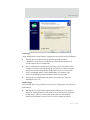
Configuring the IP Address Using the Digi Device Setup Wizard...................... 69
Configuring the IP Address Using DHCP ........................................................... 70
Configuring the IP Address using Auto-IP .......................................................... 70
Configuring the IP Address from the Command-Line Interface ......................... 71
6
Contents
Connectware Manager.......................................................................................... 71
Testing the IP Address Configuration .................................................................. 71
Configuration through the Digi Device Setup Wizard ................................................... 72
Using Port Profiles to Configure Devices ............................................................ 72
RealPort Profile .................................................................................................... 73
Console Management Profile ............................................................................... 73
TCP Sockets Profile ............................................................................................. 74
UDP Sockets Profile............................................................................................. 74
Serial Bridge Profile............................................................................................. 75
Modem Emulation Profile .................................................................................... 76
Custom Profile...................................................................................................... 76
To Further Configure the Digi Connect Device................................................... 77
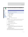
Configuration through the Default Web Interface ......................................................... 77
Open the Web Interface........................................................................................ 78
Organization of the Web Interface ....................................................................... 80
Change the IP Address, As Needed ..................................................................... 82
Configure Network Communications .................................................................. 83
Configure Mobile Settings ................................................................................... 85
Configure Serial Ports .......................................................................................... 85
Configure GPIO Pins ........................................................................................... 90
Configure Alarms ................................................................................................. 93
Configure Security Features................................................................................. 96
Configure Remote Management .......................................................................... 96
Configure System Settings ................................................................................... 97
Configuration through the Java Applet Interface ........................................................... 98
System Requirements for Using the Java Applet Interface.................................. 99
Accessing the Java Applet Interface .................................................................... 99
Organization of the Java Applet Interface.......................................................... 100
Configure Network Settings............................................................................... 102
Configure Serial Ports ........................................................................................ 103
Configure GPIO Pins ......................................................................................... 103
Configure Alarms ............................................................................................... 103
Configure Security Features............................................................................... 104
7
Contents
Configuration Through the Command Line................................................................. 104
What’s Next?................................................................................................................ 106
Chapter 3: Monitoring Digi Connect Devices ................................................................. 107
About Monitoring ........................................................................................................ 107
Monitoring Capabilities from Web-Based and Java Applet Interfaces ....................... 107
View System Information .................................................................................. 108
General System Information .............................................................................. 108
GPIO Information .............................................................................................. 109
Serial Port Information ...................................................................................... 109
Network Statistics .............................................................................................. 110
Monitoring Capabilities from Connectware Manager ................................................. 115
Monitoring Capabilities from SNMP........................................................................... 115
Monitoring Devices from the Command Line............................................................. 116
Chapter 4: Administering Digi Connect Devices ............................................................ 119
Administration from the Default Web Interface .......................................................... 119
File Management ............................................................................................... 120
Backup/Restore Device Configurations............................................................. 121
Update Firmware and Boot/POST Code............................................................ 121
Restore Device Configuration to Factory Defaults............................................ 122
Display System Information .............................................................................. 125
Reboot the Device.............................................................................................. 126
Enable/Disable Access to Services .................................................................... 126
Administration from the Java Applet Interface............................................................ 126
Backup/Restore Device Configurations............................................................. 127
Restore Device Configuration to Factory Defaults............................................ 127
Display System Information .............................................................................. 128
Reboot the Device.............................................................................................. 128
Enable/Disable Access to Services .................................................................... 128
Administration from the Command-Line Interface ..................................................... 129
Customizing the User Interface.................................................................................... 130
8
Contents
Administration from the Connectware Manager.......................................................... 130
Glossary ................................................................................................................................. 133
Index ...................................................................................................................................... 145
9
Contents
10
About this Guide
About this Guide
••••••••••••••••••••••••••••••••••••••••••••••••••••••••
Purpose
This guide introduces the features of Digi Connect™ devices, and shows you how to
configure, monitor, and administer Connect devices.
Audience
This guide is intended for those responsible for setting up a Digi Connect device. It
assumes that you are somewhat familiar with networking. A glossary is provided with
definitions for networking terms and features discussed in the content.
Scope
This guide focuses on configuration, monitoring, and administration of Digi Connect
devices. It does not cover hardware details beyond a certain level, application
development, or customization of Connect devices and interfaces to them.
Where to Find More Information
In addition to this guide, the following documents are part of the Digi Connect library.
General Release Documentation
These documents are of interest to end users of Digi Connect devices:
Digi Connect User’s Guide (this guide)
11
About this Guide
Online help and tutorials
Context-sensitive assistance available in the Web-based interface to Connect
devices.
Digi Connect Hardware Reference Guides
Quick Start Guides
RealPort® Installation Guide
Release Notes
Cabling Guides
Integration Documentation
These documents are of interest to customers who purchase the Digi Connect Integration
Kit for product customization. The Digi Connect Integration Kit includes such resources
as development board schematics for module products, firmware release notes, hardware
reference manuals, specifications, and documentation for the sample applications. For
more information, see the document Getting Started with Digi Connect included with the
Integration Kit and accessed from the Start menu (Start > Digi Connect > Getting
Started with Digi Connect).
Additional Product Information on www.digi.com
In addition to the previous documents, product information is available on the digi.com
web site, including:
Support Forums
Knowledge Base
Data sheets/product briefs
Application/solution guides
Digi Contact Information
To contact Digi International for more information about your Digi products, or for
customer service and technical support, use the following contact information:
12
Digi Connect Family User’s Guide
About this Guide
To Contact Digi International by:
Use:
Mail
Digi International
11001 Bren Road East
Minnetonka, MN 55343
U.S.A.
World Wide Web:
http://www.digi.com/support/
email
http://www.digi.com/support/
Telephone (U.S.)
(952) 912-3200
Telephone (other locations)
+1 (952) 912-3444
13
About this Guide
14
Digi Connect Family User’s Guide
Introduction
Introduction
C
H
A
P
T
E
R
1
This chapter introduces:
The devices in the Digi Connect Family
The features available in Digi Connect devices
The types of connections and data paths in which Digi Connect devices can be
used
The processes and interface options available for configuring, monitoring, and
administering Digi Connect devices
Basic safety considerations for using Digi Connect devices
The Digi Connect Family
Following is an overview of the devices in the Digi Connect Family.
Digi Connect SP™
The Digi Connect SP (Single Port) device server is the ideal platform for your custom
web- and network-enabled embedded applications. Combining Digi and NetSilicon
technology, it eliminates the hardware design effort and delivers a true device networking
solution that is powerful enough to meet your future performance requirements.
Built on leading NetSilicon 32-bit NET+ARM technology, the Digi Connect SP device
server provides a powerful off-the-shelf hardware platform for embedded web- and
network applications with a seamless migration path to embedded modules and a fully
15
The Digi Connect Family
integrated NetSilicon system-on-chip solution using the award-winning family of
Ethernet-enabled NET+ARM microprocessors.
Digi Connect Wi-SP™
The Digi Connect Wi-SP (Wireless Single Port) device server is a secure 802.11b wireless
network solution. Combining Digi and NetSilicon technology, configuration is simple
without complex integration tools. The compact hardware design delivers a powerful
networking solution to meet your performance requirements.
Built on leading NetSilicon 32-bit NET+ARM technology, the Digi Connect Wi-SP
device server provides a powerful off-the-shelf hardware platform for embedded web- and
network applications with a seamless migration path to embedded modules and a fully
integrated NetSilicon system-on-chip solution using the award-winning family of
Ethernet-enabled NET+ARM microprocessors.
Digi Connect ME™
The Digi Connect ME (Micro Embedded) device server enables manufacturers to keep
pace with ever-evolving networking technology by easily adding web-enabled network
connectivity to existing products. This network connectivity is provided without the added
complexities of extensive hardware and software integration, and at a fraction of the time
and cost that would be required to develop a custom solution.
Built on leading 32-bit ARM technology using the network-attached NetSilicon NS7520
microprocessor, the Digi Connect ME combines true plug-and-play functionality with the
freedom and flexibility of complete product customization options. These options are
based on the NetSilicon NET+Works development platform. This platform offers a
seamless migration path to a fully integrated NetSilicon system-on-chip solution.
The Digi Connect ME Integration Kit is available to help you customize the look-and-feel
of the device interface.
Digi Connect Wi-ME™
The Digi Connect Wi-ME (Wireless Micro Embedded) is a fully customizable and secure
802.11b wireless device server. It is based on the common platform design approach of the
Digi Connect family of embedded products, which minimizes design risk and reduces
16
Digi Connect Family User’s Guide
Introduction
time to market by allowing customers to easily accommodate both wired and wireless
network functionality in a single future-proof product design.
The Digi Connect Wi-ME device server is pin-compatible with the Digi Connect ME, and
makes fully transparent 802.11b integration possible without the traditional complexities
of hardware and software integration work.
Built on leading NetSilicon 32-bit NET+ARM technology, the Digi Connect Wi-ME
embedded module offers a seamless migration path to a fully integrated NetSilicon
system-on-chip solution. It combines true plug-and-play functionality with the freedom
and flexibility of complete software customization using the proven NetSilicon
NET+Works development platform.
The Digi Connect Wi-ME Integration Kit is available to help you customize the look-andfeel of the device interface.
Digi Connect EM™
The Digi Connect EM (Embedded Module) device server delivers true Web-enabled
device networking that is easy and cost-effective to implement, while being powerful
enough to meet future performance needs.
Built on leading 32-bit ARM technology using the network-attached NetSilicon NS7520
microprocessor and featuring a wide variety of connectivity options, the Digi Connect EM
provides the freedom and flexibility of complete custom product development.
The Digi Connect EM Integration Kit is available to help you customize the look-and-feel
of the device interface.
Digi Connect Wi-EM™
The Digi Connect Wi-EM (Wireless Embedded Module) device server is a fully
customizable and secure 802.11b wireless embedded module that provides integration
flexibility in a variety of connection options. Based on the common platform design
approach of the Digi Connect family of embedded products, the Digi Connect Wi-EM
minimizes design risk and reduces time to market by allowing customers to easily
accommodate both wired and wireless network functionality in a single future-proof
product design.
17
The Digi Connect Family
The Digi Connect Wi-EM wireless embedded module is pin-compatible with the Digi
Connect EM, and makes fully transparent 802.11b integration possible without the
traditional complexities of hardware and software integration work.
Built on leading NetSilicon 32-bit NET+ARM technology, the Digi Connect Wi-EM
combines true plug-and-play functionality with the freedom and flexibility of complete
software customization using the proven NetSilicon NET+Works development platform,
and offers a seamless migration path to a fully integrated NetSilicon system-on-chip
solution.
The Digi Connect Wi-EM Integration Kit is available to help you customize the look-andfeel of the device interface.
Digi Connect™ WAN
The Digi Connect WAN (Wide Area Network) wireless device server is an alternative to
traditional wired TCP/IP WANs. The Digi Connect WAN uses GSM (Global System for
Mobile communication) to connect virtually any EIA-232 serial device to your network.
Wireless cellular connectivity can be used to create primary and backup network access
for uninterrupted communication.
The Digi Connect WAN device server uses auto-connect features to maintain connection
without any airtime or usage charges until the connection is actually used. Remote access
is easy, cost-effective, and continuous through standard TCP/IP protocols.
The Digi Connect WAN device server allows remote devices to easily and cost effectively
communicate back to a central office through standard TCP/IP communications.
Digi Connect™ RG
The Digi Connect RG (Remote Gateway) wireless cellular device provides high-speed
serial-to-serial conectivity to remote devices via wireless cellular networks. The Digi
Connect RG device employs wireless cellular networks to connect virtually any EIA-232/
422/485 serial device to TCP/IP networks. It allows remote devices to communicate easily
and cost-effectively to a central office through standard TCP/UDP communications. In
addition, Digi patented RealPort® COM port redirection software supports remote
connections to serial devices as if they were actually connected to local COM ports.
Wireless communications via Digi Connect RG device servers include instant
deployment, elimination of wiring costs and problems due to wire breaks, and the ability
18
Digi Connect Family User’s Guide
Introduction
to move the connection virtually anywhere. Typical applications include utilities,
industrial automation, financial, retail/POS or any industry where remote or portable IP
connections are required.
Digi Connect™ ES
The Digi Connect ES (Extended Safety) provides sensitive serial over Ethernet
connectivity for applications. It is the first IEC 60601/EN60601 compliant device of its
kind and consists of four, eight, or 16 galvanically isolated RS-232 serial ports, with a 10/
100 Mbps network interface and Ethernet switch (eight- 16-port models). Common
applications include providing Ethernet connections from serial devices such as
ventilators, EKGs, patient monitoring systems, infusion pumps and glucose meters to the
central data management system.
Galvanical isolation provides extended electrical safety. There is no electrical path for
current to earth ground, ensuring no electrical shock when making physical contact with
the Digi Connect ES. There is no electrical path from port to port, ensuring a ground fault
will not affect the operation of the Digi Connect ES for the operation of any device
connected to it.
Features
Following is a discussion of key features in Digi Connect devices.
Hardware Features
Following are summaries of the hardware features for Digi Connect devices. For detailed
hardware specifications, see the Hardware Reference for your Digi Connect device.
Digi Connect SP
Memory: 4 MB Flash; 16 MB RAM
Serial Interface:
–
Switch-selectable EIA-232/422/485 interface (DB-9M).
–
Throughput up to 230,400 bps.
19
Features
–
5, 6, 7, 8 data bits.
–
1, 1.5, 2 stop bits.
–
Mark/space/even/odd parity.
–
Full signal support for TXD, RXD, RTS, CTS, DTR, DSR, and DCD.
–
Hardware and software flow control.
–
RTS Toggle
Power requirements: See "Power Requirements Digi Connect SP Digi Connect
Wi-SP, Digi Connect WAN, and Digi Connect RG" on page 26.
Digi Connect Wi-SP
Memory: 4 MB Flash; 16 MB RAM
Serial Interface:
–
Switch-selectable EIA-232/422/485 interface (DB-9M).
–
Throughput up to 230,400 bps.
–
5, 6, 7, 8 data bits.
–
1, 1.5, 2 stop bits.
–
Mark/space/even/odd parity.
–
Full signal support for TXD, RXD, RTS, CTS, DTR, DSR, and DCD.
–
Hardware and software flow control.
–
RTS Toggle
Power requirements: See "Power Requirements Digi Connect SP Digi Connect Wi-SP,
Digi Connect WAN, and Digi Connect RG" on page 26
Digi Connect ME
Memory: 2 MB Flash; 8 MB RAM
Serial interface:
20
–
High-speed TTL serial interface.
–
Throughput up to 230,400 bps.
–
5, 6, 7, 8 data bits.
–
1, 1.5, 2 stop bits.
–
Mark/space/even/odd parity.
Digi Connect Family User’s Guide
Introduction
–
Full signal support for TXD, RXD, RTS, CTS, DTR, DSR, and DCD.
–
Hardware and software flow control.
–
RTS Toggle
Five configurable GPIO pins
Power requirements: See "DC Characteristics for Embedded Devices Digi
Connect ME, Digi Connect Wi-ME, Digi Connect EM, and Digi Connect WiEM" on page 26.
Digi Connect Wi-ME
Memory: 4 MB Flash; 8 MB RAM
Serial interface:
–
High-speed TTL serial interface.
–
Throughput up to 230,400 bps.
–
5, 6, 7, 8 data bits.
–
1, 1.5, 2 stop bits.
–
Mark/space/even/odd parity.
–
Full signal support for TXD, RXD, RTS, CTS, DTR, DSR and DCD.
–
Hardware and software flow control.
–
RTS Toggle
Five configurable GPIO pins
Power requirements: See "DC Characteristics for Embedded Devices Digi
Connect ME, Digi Connect Wi-ME, Digi Connect EM, and Digi Connect WiEM" on page 26.
Digi Connect EM
Memory: 4 MB Flash; 8 MB RAM
Serial interface:
–
Two high-speed TTL serial interfaces.
–
Throughput up to 230,400 bps.
–
5, 6, 7, 8 data bits.
–
1, 1.5, 2 stop bits.
21
Features
–
Mark/space/even/odd parity.
–
Full signal support for TXD, RXD, RTS, CTS, DTR, DSR and DCD on port 1
–
TXD / RXD signals support on port 2.
–
Hardware and software flow control on port 1.
–
RTS Toggle
Nine configurable GPIO pins
Power requirements: See "DC Characteristics for Embedded Devices Digi
Connect ME, Digi Connect Wi-ME, Digi Connect EM, and Digi Connect WiEM" on page 26.
Digi Connect Wi-EM
Memory: 4 MB Flash; 8 MB RAM
Serial interface:
–
Two high-speed TTL serial interfaces.
–
Throughput up to 230,400 bps.
–
5, 6, 7, 8 data bits.
–
1, 1.5, 2 stop bits.
–
Mark/space/even/odd parity.
–
Full signal support for TXD, RXD, RTS, CTS, DTR, DSR and DCD on port 1.
–
TXD / RXD signals support on port 2.
–
Hardware and software flow control on port 1.
–
RTS Toggle
Nine configurable GPIO pins
Power requirements: See "DC Characteristics for Embedded Devices Digi
Connect ME, Digi Connect Wi-ME, Digi Connect EM, and Digi Connect WiEM" on page 26.
Digi Connect ES
RS-232 Serial Ports (2.5 kV)
Connect to 10/100 Mbps Ethernet LAN
Surge protection on all ports
22
Digi Connect Family User’s Guide
Introduction
Serial Interface
–
Intergrated 2-port Ethernet switch on 8 and 16-port models
–
HTTP for easy browser configuration
–
Up to 9 Telnet or Rlogin sessions per port
–
Password access
–
Firmware upgrades via TFTP
–
Save/Restore configuration to host
–
230 Kbps throughput on all ports
–
Full modem and hardware flow control
LEDs for serial Ethernet activity
Digi Connect WAN
Memory: 4MB Flash; 8 MB RAM
Serial interface:
–
Switch-selectable EIA-232 (DB-9M)
–
Throughput up to 230,400 bps
–
5, 6, 7, 8 data bits.
–
1, 1.5, 2 stop bits.
–
Mark/space/even/odd parity.
–
Full signal support for TXD, RXD, RTS, CTS, DTR, DSR, and DCD.
–
Hardware and software flow control.
DHCP Server (enabled by default)
Power requirements: See "Power Requirements Digi Connect SP Digi Connect
Wi-SP, Digi Connect WAN, and Digi Connect RG" on page 26.
Digi Connect RG
One EIA-232/422/485 serial port
10/100 Base-T Ethernet
GPRS with EDGE network for high speed wireless network connectivity
1900/850 MHz EDGE/GPRS modem for use in U.S. and other markets
23
Features
TCP/UDP socket service
Patented Digi RealPort® COM port redirector
Web and central console configuration
Supports static/dynamic and public/private IP addresses
Integrates with Digi Connectware™ Manager for easy device connectivity and
management
256-bit AES security provides encryption and authentication for data
communications
The following is a discussion of some of these key configurable hardware features.
Serial Interface Features and Options
The serial interface for Digi Connect devices includes the following features (except
where noted) and configurable options:
Full signal support for TXD, RXD, RTS, CTS, DTR, DSR, and DCD.
RTS Toggle: The RTS signal can be enabled or disabled on a given serial port.
This toggling of RTS can be used to raise RTS when sending data (not
supported in Digi Connect WAN).
Data bits 5 through 8 are supported.
Stop bits 1, 1.5, and 2 are supported.
RCI over Serial (DSR) can be enabled or disabled.
Hardware and software flow control.
Serial data over User Datagram Protocol (UDP) also known as udpserial (not
supported in Digi Connect WAN). Supported udpserial inlcudes the following
functionality:
–
controlling forwarding characteristics based on size, time, and patterns.
–
incoming datagrams from multiple destinations.
–
outgoing datagrams sent to multiple destinations.
Serial data over Transmission Control Protocol (TCP), also known as
autoconnect and tcpserial. Supported tcpserial includes the following
functionality:
–
24
controlling forwarding characteristics based on size, time, and pattern.
Digi Connect Family User’s Guide
Introduction
–
creating an autoconnection from serial port to remote network destination
based on data and/or serial hardware signals.
–
allowing incoming raw, Telnet, and SSL (secure socket) connections
–
controlling serial port via Telnet also known as RFC 2217 (not supported in
Digi Connect WAN).
Alarms: Issuing of email triggers or SNMP traps based on patterns found in
serial data (alarms feature), also emails based on General Purpose Input/Output
(GPIO) signals. See "Alarms" on page 39 for more details.
Port buffering: Allows you to monitor incoming ASCII serial data in log form.
Session management (not supported in Digi Connect WAN):
–
You can connect to a device through Telnet or Rlogin.
–
You can make connections to serial ports and switch between them using
escape key sequences.
Modem emulation over Ethernet (see also "Modem Emulation" on page 39, not
supported in Digi Connect WAN):
–
Dial into serial port from network
–
Dial out of serial port to network
–
Dial-in modem pool
Line Printer Daemon (LPD): Allows network printing over a serial port (not
supported in Digi Connect WAN).
RealPort software (see also "RealPort Software" on page 38, not supported in
Digi Connect WAN):
–
Support network serial port on many popular operating systems.
–
Support encrypted RealPort over SSL on selected operating systems.
Configurable GPIO Pins
All devices in the Digi Connect Family except the Digi Connect SP, Digi Connect ES,
Digi Connect Wi-SP and the Digi Connect WAN have a set of General Purpose I/O
(GPIO) pins. In normal operation, the GPIO pins are used for the serial CTS, DCD, DSR,
DTR, and RTS signals. On Digi Connect EM and Wi-EM devices, both sets of RXD/TXD
signals are also configured. These GPIO pins can be configured for one of three modes:
serial, input, and output.
25
Features
Serial mode allows normal serial operation.
Input mode allows input of GPIO signals. Alarms can be issued when GPIO
pins change state. Input mode is used in conjunction with alarms to trigger
emails or SNMP traps when a particular signal change is detected (see
"Alarms" on page 39).
Output mode allows output of GPIO signals. This mode can be used to toggle
the output of GPIO signals between high and low.
The configuration and current state of GPIO pins can be easily viewed, through the Web
user interface or by issuing commands from the command line.
DHCP Server
The Digi Connect WAN device is running a DHCP server. The DHCP server is enabled by
default but can be disabled in the setup wizard. Configure the setup device to obtain IP
adresses automatically. This eliminates subnet errors.
Power Requirements
The power requirements for Digi Connect devices are as follows. See also the Hardware
Reference for your Digi Connect device for additional information.
Power Requirements Digi Connect SP Digi Connect Wi-SP, Digi Connect WAN, and
Digi Connect RG
The Digi Connect SP, Digi Connect Wi-SP, Digi Connect WAN, and Digi Connect RG
must be powered by a Listed LPS or Class II power supply rated 9-30 VDC, 0.37 A
minimum. The power supply shipped with the Digi Connect WAN provides surge
protection covering 4Kv burst (EFT) per -4-4 and 2Kv surge per EN61000-4-5 (noncondensing). See the Hardware Reference or the Quick Start guide for your Digi Connect
device for additional information.
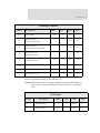
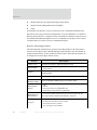
DC Characteristics for Embedded Devices
Digi Connect ME, Digi Connect Wi-ME, Digi Connect EM, and Digi Connect Wi-EM
The following tables list DC characteristics for operating conditions, inputs, and outputs
for Digi Connect ME, Digi Connect Wi-ME, Dig Connect EM, and Digi Connect Wi-EM
devices.
26
Digi Connect Family User’s Guide
Introduction
Operating Conditions
Symbol
Description
VCC
Supply Voltage
ICC
Min
Typ
Max
Unit
3.14
3.3
3.45
V
Supply Current for
Digi Connect ME & EM
—
—
270
mA
ICC
Supply Current for
Digi Connect Wi-ME & Wi-EM
—
—
400
mA
IIL
Input Current as “0”
(57K pull-up resistor)
—
—
IIH
Input Current “1”
(57K pull-up resistor)
-10
—
10
µA
IOZ
HighZ Leakage Current
-10
—
10
µA
IOD
Output Drive Strength
—
—
2
mA
CIO
Pin Capacitance (VO=0)
—
—
4
pF
µA
57
Note VCC absolute max rating is -.03V and max 3.9V
Warning The assertion of the 3.3V supply voltage must be stable within 140 ms. If
the rise time is greater than specified, it could lead to the 3-1-3 diagnostic
error.
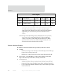
GPIO Inputs
Symbol
Description
Min
Typ
Max
Unit
VIH
Input High Voltage
2
—
VCC+0.3
V
VIL
Input Low Voltage
VSS-0.3
—
0.2*VCC
V
27
Features
GPIO Outputs
Symbol
Description
Min
Typ
Max
Unit
VOH
Output High Voltage
2.4
—
3.45
V
VOL
Output Low Voltage
0
—
0.4
V
Note The Digi Connect ME and Digi Connect Wi-ME modules use a supervisor
circuit with a 2.88 reset threshold and an internal 5k pull-up resistor. When
VCC falls to the threshold voltage, a reset pulse is issued, holding the
output in active state. When power rises above 2.88V, the reset remains for
approximately 250 ms to allow the system clock and other circuits to
stabilize.
Note The Digi Connect EM and Digi Connect Wi-EM modules use a supervisory
circuit with a 2.93V reset threshold. When VCC falls to the threshold
voltage, a reset pulse is issued, holding the output in active state. When
power rises above 2.93V, the reset remains for approximately 200 ms to
allow the system clock and other circuits to stabilize.
Network Interface Features
Key features of the network interface for Digi Connect products are as follows:
Standard:
–
IEEE 802.3 for Digi Connect SP, Digi Connect ME, Digi Connect EM, Digi
Connect WAN, and Digi Connect RG.
–
IEEE 802.11b for Digi Connect Wi-SP, Digi Connect Wi-ME and Wi-EM.
Physical layer: 10/100 Mbit Base-T for Digi Connect SP, Digi Connect ME,
Digi Connect EM, Digi Connect WAN, and Digi Connect RG.
Network data rate:
28
–
10 Mbps/100 Mbps, with auto-sensing of speed for Digi Connect SP, Digi
Connect ME, Digi Connect EM, Digi Connect WAN, and Digi Connect RG.
–
Up to 11 Mbps with automatic fallback for Digi Connect Wi-SP Digi Connect
Wi-ME and Wi-EM.
Digi Connect Family User’s Guide
Introduction
Ethernet duplex mode: full-duplex, half-duplex, with auto-sensing of duplex
mode for Digi Connect SP, Digi Connect ME, Digi Connect EM, Digi Connect
WAN, and Digi Connect RG.
Ethernet connector: RJ-45 for Digi Connect SP, Digi Connect ME, Digi
Connect WAN, and Digi Connect RG.
RJ-45 or pin header for Digi Connect EM.
Serial connector: DB-9M for Digi Connect SP, Digi Connect Wi-SP,Digi
Connect WAN, and Digi Connect RG. TTL-level pins for Digi Connect ME,
Wi-ME, Digi Connect EM, and Wi-EM.
Wireless Devices Digi Connect Wi-ME, Wi-EM, Wi-SP, and Digi Connect WAN (see
also "Wireless Networking Features" on page 30):
–
Wireless Modulation: CCK (11/5 Mbps), DQPSK (2 Mbps), DBPSK (1 Mbps)
–
Wireless Transmit Power: 16 dBm
–
Wireless Receive Sensitivity: -82 dBm at 11 Mbps
–
Wireless Antenna Connector: 1 x RP-SMA for Digi Connect Wi-ME, Wi-SP,
and Digi Connect WAN; 2 x RP-SMA for Digi Connect Wi-EM
–
Wireless Security: Wi-Fi Protected Access (WPA/WPA2/802.11i), Wired
Equivalent Privacy (WEP)
Full-duplex
Half-duplex
Auto-sensing of duplex mode
Configurable Network Services
Access to network services can be enabled and disabled. This means that you can restrict a
device’s use of services to only those strictly needed by the device. To improve device
security, you can also turn off any non-secure services, such as Telnet. Network services
that can be enabled or disabled include:
Advanced Digi Discovery Protocol (ADDP)
RealPort (not supported in Digi Connect WAN)
Encrypted RealPort (not supported in Digi Connect WAN)
HTTP/HTTPS
Line Printer Daemon (LPD) (not supported in Digi Connect WAN)
Remote Login (rlogin) (not supported in Digi Connect WAN)
29
Features
Remote Shell (rsh) (not supported in Digi Connect WAN)
Simple Network Management Protocol (SNMP)
Telnet
In the default web interface, access to network services is enabled and disabled on the
Network Services page of Network Configuration. For more information, see "Enable or
Disable Network Services" on page 84. In the Command-Line Interface, network services
are enabled and disabled through the set service command. See the Digi Connect Family
Command Reference for the set service command description.
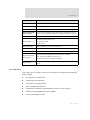
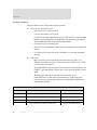
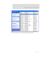
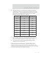
Wireless Networking Features
The following table summarizes key wireless-networking features in the Digi Connect
wireless devices (Digi Connect Wi-ME and Digi Connect Wi-EM). For more details on
support of these features, see the readme file for this release. The following features can
be configured in wireless Digi Connect devices.
Feature
Country Code
Specifies the country in which the product is used.
Network Mode
-- Infrastructure Mode
-- Ad-Hoc Mode
Channel
Can use automatic channel search-and-select or a user-configurable
channel number.
Data Rate
Auto, 1Mbps, 2Mbps, 5.5Mbps, 11Mbps
Service Set
Identifier (SSID)
A user-configurable SSID string or auto-connect option.
Authentication
Options
-- Open
-- Shared
-- Wi-Fi Protected Access (WPA2/802.11i)
-- WPA/WPA2 with pre-shared key (WPA-PSK)
802.1x
(WPA2/802.11i)
Authentication
Encryption
30
Description
-- Protected Extensible Authentication Protocol (PEAP) with EAP- MS
See "Supported WPA Authentication Methods" on page 40
-- Temporal Key Integrity Protocol (TKIP)
--Counter mode CBC MAC Protocol (CCMP)
-- Wired Equivalent Privacy (WEP)
-- Use of encryption can be disabled.
Digi Connect Family User’s Guide
Introduction
Feature
Description
Network Key
A shared key (ASCII or Hexadecimal) to be used for WEP or WPA-PSK.
Username
A username to be specified when 802.1x -based authentication (WPA) is used.
Password
A password to be specified when 802.1x based authentication (WPA) is used.
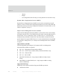
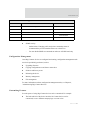
Wireless Networking
Status Features:
You can display the following status information for Wireless Digi Connect
devices. For more detailed descriptions, see "Wireless Statistics" on page 113.
Connection Status
The status of the wireless network connection.
Network Mode
The network mode currently in use:
-- Infrastructure Mode
--Ad-Hoc Mode
Data Transfer Rate
The data transfer rate of the current connection.
Channel
The wireless network channel currently in use.
SSID
The selected SSID of the wireless network.
The status of the WEP/WPA/WPA2 security features, including:
WEP / WPA security
and encryption
-- The Authentication Method currently in use
-- Whether authentication is enabled or disabled
Signal Strength
A statistic that indicates the strength of the radio signal between 0 and 100
percent.
User Interfaces
Digi Connect devices support a variety of user interfaces for configuring and monitoring
tasks, including:
The Digi Device Setup Wizard
A default web-based interface
An optional Java-applet interface
Telnet Command-Line Interface
Configuration via Remote Command Interface (RCI) over the serial port
Simple Network Management Protocol (SNMP)
Connectware Manager Console
31
Features
Some of these user interfaces may be customized. For additional details on these user
interfaces, see "Configuration Interfaces" on page 45 and "Monitoring Interfaces" on page
57.
Protocol Support
All the devices in the Digi Connect Family include a Robust on-board TCP/IP stack with a
built-in web server. The protocols supported in each Digi Connect device (unless noted
otherwise) include:
Transmission Control Protocol (TCP)
User Datagram Protocol (UDP) (not supported in Digi Connect WAN)
Dynamic Host Configuration Protocol (DHCP)
Simple Network Management Protocol (SNMP)
Secure Sockets Layer (SSL)/Transport Layer Security (TLS)
Telnet Com Port Control Option (Telnet) including support of RFC 2217
(ability to control serial port via Telnet -however, Digi Connect WAN does not
support the additional extension of RFC 2217. See "Serial Data
Communication over TCP and UDP" on page 33 for additional information
Remote Login (rlogin) (not supported in Digi Connect WAN)
Line Printer Daemon (LPD) (not supported in Digi Connect WAN)
HyperText Transfer Protocol (HTTP)/HyperText Transfer Protocol over Secure
Socket Layer (HTTPS)
Simple Mail Transfer Protocol (SMTP)
Internet Control Message Protocol (ICMP)
Internet Group Management Protocol (IGMP)
Address Resolution Protocol (ARP)
Advanced Digi Discovery Protocol (ADDP)
Point to Point Protocol (PPP) with Network Address Technology (NAT) (Only
supported in Digi Connect WAN and Digi Connect RG)
Secure Shell (SSHv2) (Only supported in Digi Connect WAN and Digi
Connect RG)
32
Digi Connect Family User’s Guide
Introduction
Global System for Mobile communication (GSM) (Only supported in Digi
Connect WAN and Digi Connect RG)
General Packet Radio Service (GPRS) (Only supported in Digi Connect WAN
and Digi Connect RG)
Enhanced Data Rates for Global Evolution (EDGE) (Only supported in Digi
Connect WAN and Digi Connect RG)
Following is an overview of some of the services provided by these protocols.
Serial Data Communication over TCP and UDP
The Digi Connect family supports serial data communication over TCP and UDP. The
only exception is the Digi Connect WAN which does not support UDP. Key features
include:
Serial data communication over TCP, also known as autoconnect and tcpserial
can automatically perform the following functions:
–
Establish bidirectional TCP connections, known as autoconnections, between
the serial device and a server or other network device. Autoconnections can be
made based on data and or serial hardware signals.
–
Control forwarding characteristics based on size, time, and pattern
–
Allow incoming raw, Telnet, and SSL/TLS (secure-socket) connections
–
Support RFC 2217 (an extension of the Telnet protocol not supported in Digi
Connect WAN)
Serial data communication over UDP, also known as udpserial (not supported
in Digi Connect WAN) can automatically perform the following functions:
–
Digi Connect devices can automatically send serial data to one or more devices
or systems on the network using UDP sockets. Options for sending data include
whether specific data is on the serial line, a specific time period has elapsed, or
after the specified number of bytes has been received on the serial port.
–
Control forwarding characteristics based on size, time, and patterns.
–
Support incoming datagrams from multiple destinations.
–
Support outgoing datagrams sent to multiple destinations.
TCP/UDP forwarding characteristics.
Extended communication control on TCP/UDP data paths.
33
Features
–
Timeout
–
Hangup
–
User-configurable Socket ID string (text string identifier on autoconnect only)
Dynamic Host Configuration Protocol (DHCP)
Dynamic Host Configuration Protocol (DHCP) can be used to automatically assign IP
addresses, to deliver TCP/IP stack configuration parameters such as the subnet mask and
default router, and to provide other configuration information. For further details, see "IP
Address Assignment" on page 37.
Simple Network Management Protocol (SNMP)
Simple Network Management Protocol (SNMP) is a protocol that can be used to manage
and monitor network devices. The SNMP architecture enables a network administrator to
manage nodes--servers, workstations, routers, switches, hubs, etc.--on an IP network;
manage network performance, find and solve network problems, and plan for network
growth. Digi devices support SNMP Version 1. For more information about using SNMP
as an interface to manage devices, see "Simple Network Management Protocol (SNMP)"
on page 55.
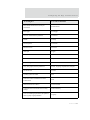
Supported RFCs and MIBs
The following SNMP-related Request for Comments (RFCs) and Management
Information Bases (MIBs) are supported:
RFC 1213 - Management Information Base (MIB) II
RFC 1215 - Generic Traps (coldStart, linkUp, authenticationFailure only)
RFC 1316 - Character MIB
RFC 1317 - RS-232 MIB
DIGI-DEVICE-INFO.mib - A Digi enterprise MIB for the Digi Connect
Family
DIGI-SERIAL-ALARM-TRAPS.mib - A Digi enterprise MIB for sending
alarms as SNMP traps
Supported SNMP Traps
SNMP traps can be enabled or disabled. Supported SNMP traps include:
Authentication failure
34
Digi Connect Family User’s Guide
Introduction
Login
Cold start
Link up
Alarms can be issued in the form of SNMP traps
Secure Sockets Layer (SSL)/Transport Layer Security (TLS)
Secure Sockets Layer (SSL)/Transport Layer Security (TLS) are used to provide
authentication and encryption for Digi Connect devices. For more information, see
"Security Features" on page 40.
Telnet
Digi Connect devices support the following types of Telnet connections:
Telnet Client
Telnet Server
Reverse Telnet, often used for console management or device management
Telnet Autoconnect
RFC 2217 (Telnet Com Port Control Option and extension of the Telnet
protocol is not supported in Digi Connect WAN)
For more information on these connections, see "Supported Connections and Data Paths"
on page 42. Access to Telnet network services can be enabled or disabled.
Remote Login (rlogin)
Users can perform logins to remote systems (rlogin). Remote Login is not supported in
Dig Connect WAN. Access to rlogin service can be enabled or disabled.
Line Printer Daemon (LPD)
The Line Printer Daemon (LPD) allows network printing over a serial port. The Line
Printer Daemon is not supported in the Digi Connect WAN. Each serial port has a
dedicated LPD server that is independently configurable. Access to LPD service can be
enabled or disabled.
35
Features
HyperText Transfer Protocol (HTTP)/Hypertext Transfer Protocol over
Secure Socket Layer (HTTPS)
Digi Connect devices provide web pages for configuration that can be secured by
requiring a user login.
Internet Control Message Protocol (ICMP)
ICMP statistics can be displayed, including the number of messages received, bad
messages received, and destination unreachable messages received.
Point-to-Point Protocol (PPP)
The Point-to-Point Protocol (PPP) transports multi-protocol packets over point-to-point
links. PPP encapsulates the data packet, allows the server to inform the dial-up client of its
IP address (or client to request the IP address), authenticates the exchange, negotiates
multiple protocols, and reassembles the data packet for network communication. Digi
Connect WAN supports PPP with NAT (Network Address Technology). NAT reduces the
need for a large amount of publicly known IP addresses by creating a separation between
publicly known and privately known IP addresses.
Advanced Digi Discovery Protocol (ADDP)
The Advanced Digi Discovery Protocol (ADDP) runs on any operating system capable of
sending multicast IP packets on a network. ADDP allows the system to identify all
ADDP-enabled Digi devices attached to a network by sending out a multicast packet. The
Digi devices respond to the multicast packet and identify themselves to the client sending
the multicast.
ADDP needs to communicate with the TCP/IP stack using UDP. The TCP/IP stack should
be able to receive multicast packets and transmit datagrams on a network.
Not all Digi devices support ADDP.
Access to ADDP service can be enabled or disabled.
36
Digi Connect Family User’s Guide
Introduction
Global System for Mobile communication (GSM) (Only supported in Digi
Connect WAN and Digi Connect RG)
The GSM protocol is a digital mobile telephone system used in Europe and other parts of
the world. There are three major types of digital mobile systems and GSM is the most
widely used. GSM compresses and digitizes data and sends it down a channel along with
two other streams of user data - each in its own time slot.
General Packet Radio Service (GPRS) (Only supported in Digi Connect WAN
and Digi Connect RG)
GPRS is based on Global System for Mobile (GSM) communication. GPRS is a packetbased wireless communication service that transports data rates from 56 up to 114 Kbps
and continuous connection to the Internet for mobile phone and computer users. Higher
data rates allow users more flexibility in the media they transmit. In theory, GPRS packetbased service costs users less than circuit-switched services since communication
channels are being used on a shared-use, as-packets-are-needed basis rather than
dedicated only to one user at a time. It should also be easier to make applications available
to mobile users because the faster data rate means that middleware currently needed to
adapt applications to the slower speed of wireless systems will no longer be needed.
Enhanced Data Rates for Global Evolution (EDGE) (Only supported in Digi
Connect WAN and Digi Connect RG)
EDGE is a faster version of the GSM wireless service and designed to deliver data at rates
up to 384 Kbps and enable the delivery of multimedia and other broadband applications to
mobile phone and computer users. The EDGE standard is built on the existing GSM
standard, using the same time-division multiple access frame structure and existing cell
arrangements.
IP Address Assignment
There are several ways to assign an IP address to a Digi Connect device:
Static IP: Assign a specific IP address to a device, through the Digi Device
Setup Wizard, the default web interface, or the Command-Line Interface.
Using Dynamic Host Configuration Protocol (DHCP). The device server’s
default configuration is as a DHCP client. Dynamic Host Configuration
37
Features
Protocol (DHCP) is an Internet protocol for automating the configuration of
computers that use TCP/IP. DHCP can be used to automatically assign IP
addresses, to deliver TCP/IP stack configuration parameters such as the subnet
mask and default router, and to provide other configuration information.
Auto Private IP Addressing (APIPA), also known as Auto-IP: A standard
protocol that will automatically assign an IP address from a reserved pool of
standard Auto-IP addresses to the computer on which it is installed. The device
is set to obtain its IP address automatically from a DHCP server. But if the
DHCP server is unavailable or nonexistent, Auto-IP will assign the device an
IP. If DHCP is enabled or responds later or you use ADDP, both will override
the Auto-IP address previously assigned.
For more details, see "Assign an IP Address to the Device" on page 69.
RealPort Software
Digi Connect devices use the patented RealPort COM/TTY port redirection for Microsoft
Windows, UNIX, and Linux environments (not supported in Digi Connect WAN).
RealPort software provides a virtual connection to serial devices, no matter where they
reside on the network. The software is installed directly on the host and allows
applications to talk to devices across a network as though the devices were directly
attached to the host. Actually, the devices are connected to a Digi device server or terminal
server somewhere on the network.
RealPort is unique among COM port re-directors because it is the only implementation
that allows multiple connections to multiple ports over a single TCP/IP connection. Other
implementations require a separate TCP/IP connection for each serial port. Unique
features also include full hardware and software flow control, as well as tunable latency
and throughput.
Access to RealPort services can be enabled or disabled.
Encrypted RealPort
Digi Connect devices support the patent-pending RealPort software with encryption. The
Digi Connect WAN does not support Encrypted RealPort. Encrypted RealPort offers a
secure Ethernet connection between the COM or TTY port and a device server or terminal
server. Encryption prevents internal and external snooping of data across the network by
encapsulating the TCP/IP packets in a Secure Sockets Layer (SSL) connection and
38
Digi Connect Family User’s Guide
Introduction
encrypting the data using Advanced Encryption Standard (AES), one of the latest, most
efficient security algorithms.
Digi’s RealPort with encryption driver has earned Microsoft’s Windows Hardware
Quality Lab (WHQL) certification.
Drivers are available for a wide range of operating systems, including Microsoft Windows
Server 2003, Windows XP, Windows 2000, Windows NT, Windows 98, Windows ME;
SCO Open Server; Linux; AIX; Sun Solaris SPARC; Intel; and HP-UX. It is ideal for
financial, retail/point-of-sale, government or any application requiring enhanced security
to protect sensitive information.
Access to Encrypted RealPort services can be enabled or disabled.
Alarms
Digi Connect devices can be configured to issue alarms, in the form of email message or
SNMP traps, when certain device events occur. These events include changes in GPIO pin
status, and data patterns in the serial stream. Receiving alarms about these conditions
provides you with the advantage of being notified when events occur, rather than having
to monitor the device on an ongoing basis to determine whether these events have
occurred.
For more information on configuring alarms, see "Configure Alarms" on page 93.
Modem Emulation
Digi Connect devices include a configuration profile that allows the device to emulate a
modem (not supported in Digi Connect WAN). Modem emulation sends and receives
modem responses to the serial device over the Ethernet instead of Public Switched
Telephone Network (PSTN). The modem emulation profile allows you maintain your
current software application but use it over the less expensive Ethernet network. In
addition, Telnet processing can be enabled or disabled on the incoming and outgoing
modem-emulation connections.
The modem-emulation commands supported in Digi Connect devices are documented in
the Digi Connect Family Command Reference.
39
Features
Security Features
Security-related features in Digi Connect devices include:
Secure access and authentication:
–
One password, one permission level.
–
Can issue passwords to device users.
–
Can selectively enable and disable IP services: network services such as ADDP,
RealPort, Encrypted RealPort, HTTP/HTTPS, LPD, Remote Login, Remote
Shell, SNMP, and Telnet, can be enabled and disabled.
–
Can control access to inbound ports.
–
Secure sites for configuration: HTML pages for configuration have appropriate
security.
–
Can control access to specific devices, IP addresses, or networds through IP
filtering.
Encryption:
–
Digi Connect devices include strong Secure Sockets Layer (SSL) V3.0/
Transport Layer Security (TLS) V1.0-based encryption: DES (56-bit), 3DES
(168-bit), AES (128-/156-bit).
–
Encrypted RealPort offers encryption for the Ethernet connection between the
COM/TTY port and the Digi Connect device. (Not supported in Digi Connect
WAN)
–
Wireless Digi Connect devices provide Wi-Fi Protected Access
(WPA/WPA2/802.11i) and Wired Equivalent Privacy (WEP) encryption
(64-/128-bit). The following table shows the supported WPA/WPA2/802.11i
authentication methods.
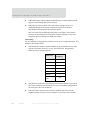
Supported WPA Authentication Methods
EAP-TLS
PEAP
EAP/TTLS
LEAP (WEP only)
EAP-PEAP/MSCHAPv2 (both PEAPv0 and PEAPv1)
EAP-TTLS/EAP-MD5-Challenge
EAP-PEAP/TLS (both PEAPv0 and PEAPv1)
EAP-TTLS/EAP-GTC
EAP-PEAP/GTC (both PEAPv0 and PEAPv1)
EAP-TTLS/EAP-OTP
EAP-PEAP/OTP (both PEAPv0 and PEAPv1)
EAP-TTLS/EAP-MSCHAPv2
40
Digi Connect Family User’s Guide
Introduction
Supported WPA Authentication Methods
EAP-TLS
PEAP
EAP/TTLS
EAP-PEAP/MD5-Challenge (both PEAPv0 and PEAPv1)
EAP-TTLS/EAP-TLS
EAP-TTLS/MSCHAPv2
EAP-TTLS/MSCHAP
EAP-TTLS/PAP
EAP-TTLS/CHAP
SNMP security:
–
Authorization: Changing public and private community names is
recommended to prevent unauthorized access to the device.
–
You can disable SNMP set commands to make use of SNMP read-only.
Configuration Management
Once Digi Connect devices are configured and running, configuration-management tasks
need to be periodically performed, such as:
Upgrading firmware
Copying configurations to and from a remote host
Software and factory resets
Rebooting the device
Memory management
File management
For more information on these configuration-management tasks, see Chapter 4,
"Administering Digi Connect Devices".
Customizing Features
Several aspects of using Digi Connect devices can be customized. For example:
The look-and-feel of the device interface for Connect devices can be
customized, to use a different company logo or screen colors.
41
Supported Connections and Data Paths
Custom Java applets can be created, using the Java configuration applet as a
sample for further development.
Redefined Custom Factory Defaults -allows you to define a new set of factory
defaults so when you revert back to factory default it will be your settings and
not the Digi default settings.
The Digi Connect Integration Kit provides a platform for evaluation, rapid prototyping,
and integration of Digi Connect embedded modules with plug-and-play firmware. It
includes tools, sample code, and documentation to help with your product integration and
web-based customization efforts. Contact Digi International for more information on the
Integration Kit and for assistance with your customization efforts.
Supported Connections and Data Paths
Digi Connect devices allow for several kinds of connections and paths for data flow
between the device and other entities. These connections can be grouped into two main
categories:
Network services, in which a remote entity initiates a connection to a Digi
Connect device.
Network/serial clients, in which a Digi Connect device initiates a network
connection or opens a serial port for communication.
Following is a discussion of these connections. The intent of this information is to
illustrate how the connections are made and data is passed. This in turn may help you
better understand the effects of enabling certain features and choosing certain settings
when configuring Digi Connect devices.
Network Services
A network service connection is one in which a remote entity initiates a connection to a
Digi Connect device. There are several categories of network services:
Network services associated with specific serial ports
Network services associated with serial ports in general
Network services associated with the Command-Line Interface (CLI)
42
Digi Connect Family User’s Guide
Introduction
Network Services Associated with Specific Serial Ports
Network service connections associated with specific serial ports include:
Reverse Telnet: A telnet connection is made to a Digi Connect device, in which
data is passed transparently between the telnet connection and a named serial
port.
Reverse raw socket: A raw TCP socket connection is made to a Digi Connect
device, in which data is passed transparently between the socket and a named
serial port.
Reverse TLS socket: An encrypted raw TCP socket is made to a Digi Connect
device, in which data is passed transparently to and from a named serial port.
LPD: A TCP connection is made to a named serial port, in which the Digi
Connect device interprets the LPD protocol and sends a print job out of the
serial port. (Not supported in Digi Connect WAN.)
Modem emulation, also known as Pseudo-modem (pmodem) (not supported in
Digi Connect WAN): A TCP connection is made to a named serial port, and the
connection will be “interpreted” as an incoming call to the pseudo-modem.
Network Services Associated with Serial Ports in General
The Digi Connect WAN does not support the following features: RealPort, Modem
emulation, and rsh. Network service connections associated with serial ports in general
include:
RealPort: A single TCP connection manages (potentially) multiple serial ports.
Modem emulation, also known as pseudo-modem (pool): A TCP connection to
the "pool" port is interpreted as an incoming call to an available pseudo-modem
in the "pool" of available port numbers.
rsh: Digi Connect devices support a limited implementation of the Remote
Shell (rsh) protocol, in that a single service listens to connections and allows a
command to be executed. Only one class of commands is allowed: a single
integer that specifies which serial port to connect to. Otherwise, the resulting
connection is somewhat similar to a reverse telnet or reverse socket connection.
Network Services Associated with the Command-Line Interface (CLI)
Network service connections associated with the Command-Line Interface (CLI) include:
Telnet: A user can Telnet directly to a Digi Connect device’s CLI.
43
Supported Connections and Data Paths
rlogin: A user can perform a remote login (rlogin) to a Digi Connect device’s
CLI. The Digi Connect WAN does not support rlogin.
Network/Serial Clients
A network/serial client connection is one in which a Digi Connect device initiates a
network connection or opens a serial port for communication. There are several categories
of network/serial client connections:
Autoconnect behavior client connections
Command-Line Interface (CLI)-based clients
Modem emulation (pseudo-modem) client connections (not supported in Digi
Connect WAN.)
Autoconnect Behavior Client Connections
In client connections that involve autoconnect behaviors, a Digi Connect device initiates a
network connection based on timing, serial activity, or serial modem signals.
Autoconnect-related client connections include:
Raw TCP connection: The Dig Connect device initiates a raw TCP socket
connection to a remote entity.
Telnet connection: The Dig Connect device initiates a TCP connection using
the Telnet protocol to a remote entity.
Raw TLS encrypted connection: The Dig Connect device initiates an encrypted
raw TCP socket connection to a remote entity.
Rlogin connection: The Dig Connect device initiates a TCP connection using
the rlogin protocol to a remote entity. (Not supported in Digi Connect WAN.)
Command-Line Interface (CLI)-based Client Connections
CLI-based client connections are available for use once a user has established a session
with the Digi Connect device’s Command-Line Interface. CLI-based client connections
include:
telnet: A connection is made to a remote entity using the Telnet protocol.
rlogin: A connection is made to a remote entity using the Rlogin protocol. (Not
supported in Digi Connect WAN.)
connect: Begin communicating with a local serial port.
44
Digi Connect Family User’s Guide
Introduction
Modem Emulation (Pseudo-Modem) Client Connections
When a port is in the modem-emulation or pseudo-modem mode, it can initiate network
connections based on AT command strings received on the serial port. (Not supported in
Digi Connect WAN.) The AT commands for modem emulation are documented in the
Digi Connect Family Command Reference.
Configuring Devices: Overview
Following is an overview of the configuration capabilities and interfaces for Digi Connect
devices. Chapter 2, "Configuring the Digi Connect Devices" covers these capabilities and
interfaces in more detail.
Configuration Capabilities
Device configuration involves setting values and enabling features for such areas as:
Network configuration: Specifying the device’s IP address and IP settings,
network-service settings, and advanced network settings.
Serial port configuration: Specifying the serial port characteristics for the
device.
GPIO pin configuration (for all devices except Digi Connect SP, Digi Connect
Wi-SP, and Digi Connect WAN): Specifying how the various GPIO pins for the
device will be used.
Alarms: Defining whether alarms should be issued, the conditions that trigger
alarms, and how the alarms should be delivered.
Security configuration: Configuring security features, such as whether
password authentication is required for device users.
System configuration: Specifying system-identifying information, such as a
device description, contact person, and physical location.
Configuration Interfaces
There are several interfaces available for configuring devices, including:
45
Configuring Devices: Overview
The Digi Device Setup Wizard, which helps you set up an IP address for the
device and quickly configure features.
A default web-based interface embedded with the product. This interface also
provides device configuration profiles.
An optional Java applet that can be used for web-based device configuration,
and as a sample application for customization and further application
development.
A Command-Line Interface (CLI).
Connectware Manager, a configuration interface to fine tune or monitor the
Connectware devices. Connectware Manager cannot assign an IP address but it
can change one.
Remote Command-line Interface (RCI) protocol.
Simple Network Management Protocol (SNMP).
Following is more information about each type of interface, the advantages of each
interface, how to access the interface, and where to find more information.
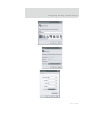
The Digi Device Setup Wizard
A wizard for configuring Connect devices, called the Digi Device Setup Wizard, is
provided on the CD shipped with each device. The Digi Device Setup Wizard is available
in Microsoft Windows or UNIX platforms. Using the Digi Device Setup Wizard is the
recommended and preferred method for configuration. It assigns an IP address for the
device, configures the device based on your description of the device environment, and
determines whether you need to install RealPort.
46
Digi Connect Family User’s Guide
Introduction
Advantages
Using the Digi Device Setup Wizard to configure devices provides several advantages:
The Digi Device Setup Wizard is the preferred approach for initial
configuration. For most users, the Digi Device Setup Wizard interface will
provide adequate device configuration.
Device configuration is made easier by providing a set of port profiles which
configure a serial port based on the way the port will be used. Each port profile
displays the relevant settings for the configuration. There are several profile
choices, including RealPort, Console Management, TCP Sockets, UDP
Sockets, Serial Bridging, Modem Emulation, and a Custom profile.
The Digi Device Setup Wizard is intended to be run only once, and is not
installed on a user’s PC.
Disadvantages
While the Digi Device Setup Wizard provides for easy configuration, it presents some
disadvantages:
The Digi Device Setup Wizard requires Microsoft Windows for full support,
and the PC running Windows usually needs to be on same network segment as
the Digi device. The Unix version of the Wizard does not include all the
features of the Windows version. The Unix version is limited to network
47
Configuring Devices: Overview
configuration settings, and does not allow you to configure or choose a scenario
through port profiles.
Some sites disallow users from running wizards, which would prevent users at
such sites from using this interface.
While the configuration capabilities of the Digi Device Setup Wizard are
acceptable for most Connect device users, it only provides for the most
common configuration scenarios, and is not as flexible as configuring through
the default web interface Interface or the command line.
How to access the Digi Device Setup Wizard
To access the Digi Device Setup Wizard, insert the Software and Documentation CD that
accompanies your Digi Connect device in a PC’s CD drive. The Digi Device Setup
Wizard will automatically start.
Where to find more information
See "Configuration through the Digi Device Setup Wizard" on page 72 for details on
running the wizard. The Digi Device Setup Wizard also has online help, accessed from the
Help button on wizard screens. In addition, the Getting Started Guide for the Digi Connect
Family Integration Kit provides discussions of the various communications models from
which you can choose.
The Default Web Interface
A default web interface is provided as an easy way to configure and monitor Digi Connect
devices. Configurable features are grouped into several categories: Network, Serial Port,
GPIO (for all devices except Digi Connect SP, Digi Connect Wi-SP, and Digi Connect
WAN), Alarms, Security, and System. Most of the configurable features are arranged by
most basic settings on a page, with associated and advanced settings accessible from that
page. As in the Digi Device Setup Wizard, serial-port configurations are classified into port
profiles, or configuration scenarios that allow you to select the scenario that best represents
the environment and set up the appropriate parameters that are needed.
When configuring some features, you may want to establish a basic configuration using
the Digi Device Setup Wizard, and then fine-tune the configuration using the default web
interface.
48
Digi Connect Family User’s Guide
Introduction
Digi Connect WAN Configuration and Management
WAN
192.168.2.1
Advantages
Using the default web interface to configure devices provides the following advantages:
Ease of use, including point-and-click functionality and wizards that make
configuration quick and complete.
Secure access to devices.
No need for programming experience.
Port profiles simplify the configuration process.
Disadvantages
You must have Internet access.
This method requires that you configure the IP address before you can access
the configuration from the web interface, however, some features cannot be
configured this way.
Accessing the Default Web Interface
To access the default web interface, enter the Digi Connect device’s IP address or host
name in a browser’s URL window. The main menu of the web interface is displayed.
49
Configuring Devices: Overview
Where to find more information
For more information, see "Configuration through the Default Web Interface" on page 77.
The default web interface has a tutorial, accessed from the Home page, and online help,
accessed from the Help link on each page. In addition, the Getting Started Guide for the
Digi Connect Family Integration Kit provides discussions of the various communications
models from which you can choose.
Java Applet Interface
An alternative configuration interface is provided with Digi Connect devices, in the form
of a Java applet. This interface provides many, but not all, of the configuration choices
available through the default web interface.
The Java applet is primarily intended as a sample alternative interface for embedded
products. Embedded product manufacturers can use the applet as a base for their custom
user interface. Because the interface is customizable, embedded product manufacturers
can use it to provide a totally unique user interface that represents the kind of device the
Digi Connect device is being embedded into. For example, the configuration interface for
a printer would look nothing like the default web interface. Today, the only way to create a
totally custom interface to the device is through an applet or other Remote Command
Interface (RCI) application. The applet can be slightly modified using a configuration file,
or it can be changed extensively. In addition, it can be used as a sample by those
customers who choose to writer their custom configuration user interface from scratch.
50
Digi Connect Family User’s Guide
Introduction
Advantages
Using the Java applet interface to configure devices provides the following advantages:
A completely customizable interface. For example, you can change the look of
the web interface by adding your company logo or changing the colors used in
the interface workspace.
The Java applet can also be used as a basis for further interface development.
That is, if the Java applet is adequate for most of your configuration needs, but
needs some modifications, then you can customize the applet’s operation. If
you want a totally unique user interface, you can use the Java applet as a
sample program that illustrates how this can be done. The applet can be used as
a starting point from which to build new interfaces. It illustrates such concepts
as configuring various aspects of the device using the RCI, applet packaging,
and Swing user interface. You can write custom management applications in
other languages that run on a separate system in the network and talk to the
device using RCI. For example, a printer manufacturer might have a
51
Configuring Devices: Overview
configuration utility written in C++ that is installed on the PC along with the
print driver.
Disadvantages
The Java applet requires that the Sun Java Runtime environment be loaded.
The Java applet does not allow for configuration of as many features as the
default web interface.
The Java applet interface is essentially frozen, and will not be updated with
additional configurable features or values in future releases.
There is limited online help for the Java applet configuration screens. If you
need more information on configurable areas, fields, and selectable values, it is
recommended that you familiarize yourself with these areas by reviewing the
online help for the default web interface.
Accessing the Java applet configuration interface
You can access the Java applet interface from the User Interface section of the Home page
of the default web interface. You can either click the Launch button next to the Custom
Interface option to launch the Java applet, or click the Set as Default to set the Java applet
as the default device interface. In some cases, your device’s default device interface may
have already been preset to the Java applet by a system administrator.
Where to find more information
See Chapter 2 for more information on using the Java applet to configure devices. While
that chapter primarily focuses on configuring Connect devices from the default web
interface, it also covers configuration from the Java applet, primarily the differences from
the default Web interface. In addition, the Getting Started Guide for the Digi Connect
Family Integration Kit provides discussions of the various communications models from
which you can choose.
For details on customizing the applet, See the Getting Started Guide for the Digi Connect
Family Integration Kit.
The Command-Line Interface
Connect devices can be configured by issuing commands from the command line. The
Command-Line Interface allows communication directly without a graphical interface. For
example, the following is a command issued from the command line to set general serial
configuration options:
52
Digi Connect Family User’s Guide
Introduction
set serial baudrate=9600 flowcontrol=hardware
Advantages
Using the command-line interface to configure devices provides the following
advantages:
Flexibility. Although the Command-Line Interface is for experienced users and
considered complex, it allows flexibility for precise configuration alterations.
Direct communication to device or system.
Can be used in UNIX or Linux environments.
Disadvantages
Users must have experience issuing commands.
This interface is not intended for Windows environments.
Command documentation is required.
The command line allows you the greatest flexibility to configure your device,
but is also considered complex.
Accessing the command line
Users access the command line via a Telnet connection or through Hyperterm to set up the
configuration. To access the device, specify the device IP address as the IP address of the
Telnet server. Depending on the serial port profile used for a Digi Connect device, you can
Telnet directly to the device using the telnet command, or perform a remote login using the
rlogin command.
Where to find more information
See the Digi Connect Family Command Reference for command descriptions and
examples of entering configuration commands from the command-line interface. In
addition, online help is available for the commands, through the help and ‘?’ commands.
The Connectware Manager Interface
In the Connectware Manager interface, devices can be managed from the Devices menu.
Tasks such as configuring, rebooting, disconnecting, and redirecting devices are available.
You can also backup/restore device configuration properties, and import or export the
device configuration properties.
The server itself can also be managed from the Server menu of the
Connectware Manager Console. From this menu, you can shut down the
53
Configuring Devices: Overview
server, stop and restart it, and reconfigure the server as needed. You can also
display reports and logs on server activity.
Advantages
Allows multiple devices to be managed (configured and monitored) from one
source.
Server can also be managed from same location.
Logs and reports can be generated and reviewed. Summaries or totals can be
linked back to the original devices for more thorough investigations.
Disadvantages
Devices must be provisioned (assigned an IP address) before they can be
accessed on Connectware Manager (use the Digi Connect Wizard to provision
devices.)
Must have Internet access.
The Remote Command Interface (RCI)
Remote Command Interface (RCI) is a programmatic interface for configuring and
controlling Connect family devices. RCI is an XML-based request/response protocol that
allows a caller to query and modify device configurations, access statistics, reboot the
device, and reset the device to factory defaults.
Unlike other configuration interfaces that are designed for a user, such as the commandline or browser interfaces, RCI is designed to be used by a program. A typical use of RCI
is in a Java applet that can be stored on the Connect device to replace the default web
interface with a custom browser interface. Another example is a custom application
running on a PC that monitors and controls an installation of many Connect devices.
Advantages
As RCI is designed to be used by a program, it is useful when creating a custom
configuration user interface, or if you want to create utilities to configure or
initialize devices through external programs or scripts.
Disadvantages
Using RCI as a device configuration interface presents these disadvantages:
54
Digi Connect Family User’s Guide
Introduction
RCI uses HTTP as the underlying transport protocol. Depending on the
network configuration, use of HTTP as a transport protocol could be blocked
by some firewalls.
RCI is quite complex to use, requiring users to phrase configuration requests in
Extensible Markup Language (XML) format. It is a "power-user” option,
intended more for users developing their own user interfaces, or for users
implementing embedded control (and thus potentially using RCI over serial)
than for end-users with limited knowledge of device programming.
Not all actions taken through the default web interface have direct equivalents
in RCI. Therefore, it may not be easy for some end-users to determine what
needs to be sent via XML for a particular style of request.
Accessing the Remote Command Interface
RCI access consists of program calls.
Where to find more information
See the Digi Connect Integration Kit for more details on RCI.
Simple Network Management Protocol (SNMP)
Simple Network Management Protocol (SNMP) is a protocol for managing and
monitoring network devices. The SNMP architecture enables a network administrator to
manage nodes--servers, workstations, routers, switches, hubs, etc.--on an IP network;
manage network performance, find and solve network problems, and plan for network
growth. Digi devices support SNMP Version 1.
Advantages
SNMP is easy to implement in extensive networks.
Programming new variables is easy.
SNMP is widely used. SNMP is a standard interface that integrates well with
network management stations in an enterprise environment. While its
capabilities are limited to device monitoring and display of statistics in Connect
devices, read/write capabilities are expected to be added to Connect devices in
future releases.
It is easy to ‘drop in’ new devices.
55
Configuring Devices: Overview
Disadvantages
As device communication is UDP-based, the communication is not secure. If
you require more secure communications with a device, you will need to use an
alternate interface.
Using SNMP, you cannot do as many tasks as you can from the default web
interface, such as file management, uploading firmware, or backing up/
restoring configurations.
Compared to the default web interface or the command-line interface, SNMP is
limited in its ability to set specific parameters, such as set port profile, is not
possible.
Accessing the SNMP Interface
Accessing the SNMP interface requires a tool, such as a network management station. The
management station relies on an agent at a device to retrieve or update the information at
the device, including Device configuration, status, and statistical information. This
information is viewed as a logical database, called a Management Information Base
(MIB). MIB modules describe MIB variables for a variety of device types and computer
hardware and software components.
The MIB for managing a TCP/IP network, called MIB-II, is an update on the original
MIB, now called MIB-I. MIB-II contains variable definitions that describe the most basic
information needed to manage a TCP/IP network. These variable definitions are organized
into several groups, such as groups for managing the system, network interfaces, address
translation, transmission media, and various protocols, including IP, ICMP, TCP, UDP,
EGP, and SNMP.
In addition to the standard MIBs, Digi Connect devices use several Digi enterprise MIBs,
including MIB DIGI-DEVICE-INFO.mib for handling device information, and
DIGI-SERIAL-ALARM-TRAPS.mib for handling alarms sent as SNMP traps.
Where to find more information
A variety of resources about SNMP are available, including reference books, and
overviews and other files on the Internet. For an overview of the SNMP interface and the
components of MIB-II, point your Internet browser to the address www.rfceditor.org, and
enter “MIB-II.” From the results, you can display a text file describing the SNMP
interface, titled “Management Information Base for Network Management of TCP/IPbased internets: MIB-II.” You can also view the text of the Digi enterprise MIBs.
56
Digi Connect Family User’s Guide
Introduction
For additional discussion of using SNMP as a device monitoring interface, see
"Monitoring Capabilities from SNMP" on page 115.
Monitoring Devices: Overview
Following is an overview of the capabilities and interfaces for monitoring Digi Connect
devices. Chapter 3, "Monitoring Digi Connect Devices" covers these capabilities and
interfaces in more detail.
Monitoring Capabilities
Monitoring Digi Connect devices includes such tasks as checking device status, viewing
information on a device’s GPIO pins, checking runtime state, viewing serial port
operations, and reviewing network statistics.
Monitoring Interfaces
As with device configuration, there are several interfaces available for configuring
devices, including:
The default web interface embedded with the product
The optional Java applet
SNMP
The Command-Line Interface
Connectware Manager
Following is more information about each type of interface, the advantages of each
interface, how to access the interfaces, and where to find more information.
Default Web and Java Applet Interfaces
The default web interface provides several screens for monitoring devices, including:
Serial Port Management: for each port, the port’s description, current profile,
and current serial configuration.
Connections Management: A display of all active system connections.
57
Administering Devices: Overview
System Information:
–
General device information
–
Current GPIO pin states
–
Serial port information: for each port, the port’s description, current profile, and
current serial configuration. This is the same information displayed by
choosing Serial Port Management.
–
Network statistics: statistics for IP, TCP, UDP, and ICMP
SNMP
The monitoring capabilities of SNMP include managing network performance, gathering
device statistics, and finding and solving network problems. For more information on
using SNMP for device-monitoring purposes, see "Monitoring Capabilities from SNMP"
on page 115.
Command-Line Interface
Several commands that can be issued from the command line to monitor devices. For a
review of these commands and what they can provide from a device-monitoring
perspective, see "Monitoring Devices from the Command Line" on page 116.
Connectware Manager
The monitoring capabilities can be sorted by the server and the devices managed by the
server. The information is available in logs and can be generated into reports. When
available, the reports post linked totals that can be drilled back to the original devices that
make up the activity of the report.
Administering Devices: Overview
Periodically, you will need to perform administrative tasks on Digi Connect devices, such
as:
Uploading and managing files
Changing the password for logging onto the device
Backing up and restoring the configuration
58
Digi Connect Family User’s Guide
Introduction
Updating firmware
Restoring the configuration to factory defaults
Rebooting the module
Chapter 4, "Administering Digi Connect Devices" covers device administration in more
detail.
RF Exposure Statement
Digi Connect Wi-SP, Digi Connect Wi-EM, and Digi Connect Wi-ME
The Digi Connect Wi-EM and Wi-ME embedded modules comply with the RF exposure
limits for humans as called out in RSS-102.
These devices are exempt from RF evaluation based on its operating frequency of 2400
MHz, and effective radiated power of 100 milliwatts. This would be less than the 3 watt
requirement for a mobile device (>20 cm separation) operating at 2400 MHz.
Digi Connect WAN and Digi Connect RG
In order to comply with RF exposure limits established in the ANSI C95.1 standards, the
distance between the antenna(s) and the user should not be less than 20 cm.
FCC Certifications for Digi Connect ES and Digi Connect RG
For FCC certification for other Digi Connect devices, see the Hardware Reference.
FCC Part 15 Class A
These devices comply with part 15 of the FCC rules. Operation is subject to the following
two conditions: (1) These devices may not cause harmful interference, and (2) These
devices must accept any interference received, including interference that may cause
harmful operation.
59
FCC Certifications for Digi Connect ES and Digi Connect RG
Radio Frequency Interference (RFI) (FCC 15.105)
This equipment has been tested and found to comply with the limits for Class A digital
devices pursuant to Part 15 of the FCC Rules. These limits are designed to provide
reasonable protection against harmful interference in a residential environment. This
equipment generates, uses, and can radiate radio frequency energy, and if not installed and
used in accordance with the instruction manual, may cause harmful interference to radio
communications. However, there is no guarantee that interference will not occur in a
particular installation. If this equipment does cause harmful interference to radio or
television reception, which can be determined by turning the equipment off and on, the user
is encouraged to try and correct the interference by one or more of the following measures:
Reorient or relocate the receiving antenna.
Increase the separation between the equipment and the receiver.
Connect the equipment into an outlet on a circuit different from that to which
the receiver is connected.
Consult the dealer or an experienced radio/TV technician for help.
Labeling Requirements (FCC 15.19)
This device complies with Part 15 of FCC rules. Operation is subject to the following two
conditions: (1) this device may not cause harmful interference, and (2) this device must
accept any interference received, including interference that may cause undesired
operation.
Modifications (FCC 15.21)
Changes or modifications to this equipment not expressly approved by Digi may void the
user's authority to operate this equipment.
Cables (FCC 15.27)
Shielded cables must be used to remain within the Class A limitations.
60
Digi Connect Family User’s Guide
Introduction
Industry Canada
This digital apparatus does not exceed the Class B limits for radio noise emissions from
digital apparatus set out in the Radio Interference Regulations of the Canadian Department
of Communications.
Le present appareil numerique n'emet pas de bruits radioelectriques depassant les limites
applicables aux appareils numeriques de la class B prescrites dans le Reglement sur le
brouillage radioelectrique edicte par le ministere des Communications du Canada.
International EMC Standards
:
Electromagnetic Emissions Standards
Digi Connect RG
Digi Connect ES
EN55022
EN55022
EN55024
EN55024
VCCI
EN60601-1-2
IEC/UL/EN 60601-1
EN55011
AS 3548
AS/NZS 3548
AS/NZS CISPR -22
CAN/CSA 22.2 60950-1-3
ICES-003
IEC/UL/EN 60950-1
Safety Standards
There are no user serviceable parts inside the Digi Connect ES. Contact your Digi
representative through "Digi Contact Information" on page 12 for repair information.
61
Important Safety Information
Safety Standards
Digi Connect RG
Digi Connect ES
UL 60950
UL 60950-1
CSA 22.2 No. 60950
CSA 22.2 No. 60950
EN60950
EN60950
IEC/EN 60601-1
UL/CUL 60601-1
Important Safety Information
To avoid contact with electrical current:
Never install electrical wiring during an electrical storm.
Never install an Ethernet connection in wet locations unless that connector is
specifically designed for wet locations.
Use caution when installing or modifying Ethernet lines.
Use a screwdriver and other tools with insulated handles.
You and those around you should wear safety glasses or goggles.
Do not place Ethernet wiring or connections in any conduit, outlet or junction
box containing electrical wiring.
Installation of inside wire may bring you close to electrical wire, conduit,
terminals and other electrical facilities. Extreme caution must be used to avoid
electrical shock from such facilities. You must avoid contact with all such
facilities.
Ethernet wiring must be at least 6 feet from bare power wiring or lightning rods
and associated wires, and at least 6 inches from other wire (antenna wires,
doorbell wires, wires from transformers to neon signs), steam or hot water
pipes, and heating ducts.
62
Digi Connect Family User’s Guide
Introduction
Do not place an Ethernet connection where it would allow a person to use an
Ethernet device while in a bathtub, shower, swimming pool, or similar
hazardous location.
Protectors and grounding wire placed by the service provider must not be
connected to, removed, or modified by the customer.
Do not touch uninsulated Ethernet wiring if lightning is likely!
External Wiring: Any external communications wiring you may install needs to
be constructed to all relevant electrical codes. In the United States this is the
National Electrical Code Article 800. Contact a licensed electrician for details.
Do not touch or move the antenna(s) while the unit is transmitting or receiving.
Do not hold any component containing a radio such that the antenna is very
close to or touching any exposed parts of the body, especially the face or eyes,
while transmitting.
Do not operate a portable transmitter near unshielded blasting caps or in an
explosive environment unless it is a type especially qualified for such use.
Antenna use:
–
Warning for laptop users: In order to comply with the FCC RF exposure limits,
it is recommended when using a laptop with a PC client adapter, that the
adapter's integrated antenna should not be positioned closer than 2 inches (5
cm) from your body or nearby persons for extended periods of time while it is
transmitting (or operating). If the antenna is positioned less than 2 inches (5
cm) from the user, it is recommended that the user limit exposure time.
Digi Connect ES Specifications
Environmental
Ambient Temperature - 0o - 55oC (32o to 130o F)
Relative Humidty - 5 to 95% (non-condensing)
Storage and Transport Temperature - 30o to 85o C (-122o to 185o F)
Altitude - 3657.6 meters (12000 feet)
Serial Port Protection (ESD): +15 kV human body model
63
Digi Connect ES Specifications
Power Requirements
Internal 100-240V
Input frequency 50-60 Hz
Input current protection - 2.0 A / 250 V(Time Lag) rated fuse
UL certified
Surge protection
4 kV burst (EFT) per EN61000-4-4
4 kV isolation input to output
2 kV surge per EN61000-4-5
Mechanical
Length - 23.5 cm (9.3 in)
Width - 26.9 cm (10.6 in)
Depth - 4.2 cm (2.1 in)
64
Digi Connect Family User’s Guide
Configuring the Digi
Connect Devices
C
H
A
P
T
E
R
2
This chapter describes how to configure Digi Connect devices. It covers the following
topics:
Alternative configuration options for the Digi Connect Wi-SP
Assign an IP address to the device, using one of the several alternative methods
–
Configuration through the Digi Device Setup Wizard
–
Configuration through the default web interface
–
Configuration through the Java applet
–
Configuration through the Command-Line Interface
–
Customization through the Connectware Manager interface
The primary focus of this chapter is on configuring devices through the default web
interface. Configuration through the Java applet interface is mentioned, but not at the
same level as the default web interface. Connectware Manager interface cannot set the IP.
To use Connectware Manager you must set up the Digi device with the Digi Device Setup
Wizard and then install Connectware Manager. For more information, see the
Connectware Manager User’s Guide.
Alternative Configuration Options for Digi Connect Wi-SP
If you prefer to configure the Digi Connect Wi-SP with a serial connection, you have
several alternative options.
65
Configure with an Access Point - Infrastructure Mode
1
Configure your network using an access point with the SSID - Connect and all
encryption disabled (such as WEP & WPA).
2
Power up the device.
3
Launch the Discovery program and proceed with the configuration.
Configure without an Access Point - Laptop with a Wireless Card Ad-Hoc Mode
1
Configure the wireless card to operate in Ad-Hoc mode with the SSID - Connect.
2
Power up the device.
3
Launch the Discovery application on the laptop and proceed with the configuration.
Command Line Access
1
Connect the Digi Connect Wi-SP to a PC with a serial cable.
2
Set the Digi Connect Wi-SP DIP switches in the On or up position.
ON
1 2 3 4
DIP Switch settings for Command Line access
for both the Digi Connect Wi-SP and the Digi Connect SP.
3
Access a terminal emulation program such as HyperTerm
Start > Accessories > Communication > Hyperterm and enter a name for
the connection.
4
Select COM1 and click OK
5
Set the port settings to 9600, 8, None, 1, None (default settings) click Apply then
OK.
6
Enter the login username - root
and the default password -dbps
7
66
Go to the Digi Connect Family Command Reference on the enclosed CD for the
command descriptions. See the set wlan command for all parameters.
Digi Connect Family User’s Guide
Configuring the Digi Connect Devices
67
login: root
password: dbps
#>
8
After you have configured the Digi Connect Wi-SP parameters to function within
your network, disconnect the power supply and the serial cable from your Digi
Connect Wi-SP
9
Reset your DIP switch settings according to your serial device requirements (EIA232/422/485).
EIA-232
Switch
Settings
EIA-485
EIA-422/485
Full-Duplex Half-Duplex
Up/On
*
Down/Off
DB-9
Pinouts
1
2
3
4
5
6
7
8
9
Shell
DCD
RxD
TxD
DTR
GND
DSR
RTS
CTS
RI
GND
CTSRxD+
TxD+
RTSGND
RxDRTS+
CTS+
TxD-
**
Not Used
RxD+
TxD+
Not Used
GND
RxDNot Used
Not Used
TxD-
*If switch 4 is up, termination resistor connected
If down, termination resistor not connected.
10
Connect the antenna and the power supply to the Digi Connect Wi-SP.
11
Insert the Software & Documentation CD and follow the wizard to discover and the
configure your Digi Connect Wi-SP for your network.
Note You may also use the Digi support site http://www.digi.com/support/ for
additional command resources.
68
Digi Connect Family User’s Guide
Configuring the Digi Connect Devices
Assign an IP Address to the Device
There are several ways to assign an IP address to a device:
Using the Digi Device Setup Wizard.
Using Dynamic Host Configuration Protocol (DHCP) from the default web
interface (only for changing the IP address once it has been assigned).
Using the Command-Line Interface.
Using Automatic Private IP Addressing (APIPA), also known as Auto-IP.
Configuring the IP Address Using the Digi Device Setup Wizard
Using the Digi Device Setup Wizard is the preferred method of assigning an IP address
and initially configuring your Digi Connect device. The Digi Device Setup Wizard is
supplied on the CD that accompanies your Digi Connect device.
The Digi Device Setup Wizard “discovers” the device, and then provides a method for
assigning an IP address as well as configuring your device for your needs. It can be used
in conjunction with the web interface to ‘tweak’ the specific environment. Setup is
specially designed for the Windows environments, and is quick, automated, and complete.
Prerequisites
This procedure assumes the following:
The device server is connected to the network and powered up.
The CD will be used on a system running Microsoft Windows operating system
or a Unix operating system.
That you have located the device server’s MAC address, located on the label on
the bottom of the product, and recorded it for later use in assigning an IP
address.
Procedure
1
Insert the Digi CD in the CD drive.
2
If the CD does not start automatically, double-click My Computer > CD ROM
Drive > setup.exe
69
Assign an IP Address to the Device
3
The Digi Device Setup Wizard will automatically pop up. Select your platform and
click Next.
The Digi application finds and lists all of the Digi devices on your network.
4
Locate your device server by its MAC address.
5
Select the device server and then click Next.
Follow the instructions in the wizard to configure your Digi Connect device. Use the
online help supplied with the wizard if you need more information about values the
wizard prompts you to supply and select.
Configuring the IP Address Using DHCP
Using DHCP from the default web interface to configure an IP address works only for
changing the IP address of a device server that has already been assigned an IP address.
However, once an IP address is assigned, any configuration changes can be made from the
Web interface.
Prerequisite
This procedure assumes the following:
That the device server is configured as a DHCP client. Since this is the default
configuration, this will be the case unless the configuration has been changed.
That the device server is not powered on
Procedure
1
Set up a permanent entry for the device server on a DHCP server.
2
Connect the device server to the network and power it on. The IP address
configured in step 1 is assigned automatically.
Configuring the IP Address using Auto-IP
The standard protocol Automatic Private IP Addressing (APIPA or Auto-IP) assigns the
IP address from the reserved IP addresses in Auto-IP. Use ADDP or DHCP to find the
device and assign it a new IP address that is compatible with your network. Once the unit
is plugged in, Auto-IP automatically assigns the IP address.
70
Digi Connect Family User’s Guide
Configuring the Digi Connect Devices
Configuring the IP Address from the Command-Line Interface
The set network command is used to configure an IP address from the command line. To
configure the Digi Connect SP through the command line, the DIP switches must be
changed. See "Command Line Access" on page 66 for an illustration of the DIP switch
settings. On the set network command, include the following parameters:
ip=device ip: The IP address for the device.
gateway=gateway: The network gateway IP address.
submask=device submask: The device submask.
dhcp=off: Turns off use of the Dynamic Host Configuration Protocol (DHCP),
so that the IP address assigned is permanent.
static=on: Specifies that the IP address is static, and will remain as the specified
IP address, gateway, and submask.
For example:
set network ip=10.0.0.1 gateway=255.255.255.0
submask=255.255.255.0 dhcp=off static=on
Connectware Manager
The IP address cannot be set in Connectware Manager but it can be changed.
Open the browser based on the IP address the device has and go to Configuration >
Network > IP Settings and enter the new IP address, subnet mask, and gateway.
Testing the IP Address Configuration
Once the IP address is assigned, you should test the IP address configuration to be sure it
works as configured.
Prerequisite
This procedure assumes that you have configured the device server with an IP address.
Procedure
1
Access the command line of a PC or other networked device.
2
Issue the following command:
71
Configuration through the Digi Device Setup Wizard
ping ip-address
where ip-address is the address you assigned to the device server.
Example
ping 192.168.2.2
A reply should be returned.
Configuration through the Digi Device Setup Wizard
The Digi Device Setup Wizard helps you configure the device according to one of several
port profiles, or configuration scenarios that characterize the manner in which the device
will be used.
Using Port Profiles to Configure Devices
The Digi Device Setup Wizard allows you to configure a serial port based on the way the
port will be used. Each port profile displays the relevant settings for the configuration.
There are several port profile choices for the Connect Family but if you see a profile listed
that is not available in your brower, it means your device does not support the feature. The
profiles are described in more detail on the following pages:
RealPort: Allows you to map a COM or TTY port to the serial port. (Not
supported in Digi Connect WAN)
Console Management: Allows you to access a device’s console port over a
network connection.
TCP Sockets: Allows a serial device to communicate over a TCP network.
UDP Sockets: Allows a serial device to communicate using UDP.(Not
supported in Digi Connect WAN)
Serial Bridge: Configures one side of a serial bridge. A bridge connects two
serial devices over the network, as if they were connected with a serial cable.
Modem Emulation: Allows you to configure the serial port to act as a modem.
(Not supported in Digi Connect WAN.)
72
Digi Connect Family User’s Guide
Configuring the Digi Connect Devices
Custom: An advanced option to allow full configuration of the serial port. This
profile allows you to view all settings associated with the serial port.
RealPort Profile
The RealPort Profile allows you to configure your device to create a virtual COM port on
your PC, known as COM Port Redirection. (Not supported in Digi Connect WAN.) The
PC applications send data to this virtual COM port and RealPort sends the data across the
network to the Digi device server. The data is routed to the serial device connected to the
Digi device server’s serial port. The network is transparent to both the application and the
serial device (not supported in Digi Connect WAN).
@@@ RealPort software (from the Software and Documentation CD) must be
installed and configured on each PC that will use RealPort ports. Enter the IP
address of the Digi device server and the RealPort TCP port number 771.
Console Management Profile
The Console Management Profile allows access to a device's console port over a network
connection. Most network devices such as routers, switches, and servers offer serial
port(s) for management. Instead of connecting a terminal to the console port, cable the
console port to the serial port of your Digi device. Then using Telnet features, network
administrators can access these consoled serial ports from the LAN by addressing the
appropriate TCP port.
73
Configuration through the Digi Device Setup Wizard
TCP Sockets Profile
The TCP Sockets profile allows serial devices to communicate over a TCP network. The
TCP Server allows other network devices to initiate a TCP connection to the serial device
attached to the serial port of the Digi device server. The TCP Client allows the Digi device
server to automatically establish a TCP connection to an application or a network.
RFC 2217 Support
Digi Connect devices -except Digi Connect WAN support RFC 2217, an extension of the
Telnet protocol used to access serial devices over the network. RFC 2217 implementations
enable applications to set the parameters of remote serial ports (baud rate, flow control,
etc.), detect line signal changes, as well as receive and transmit data. The configuration
information provided in this section applies to Digi Connect devices functioning as RFC
2217 servers.
If using the RFC 2217 protocol, do not modify the port settings from the defaults. If you
have altered the device server, restore the factory default settings (see "Restore Device
Configuration to Factory Defaults" on page 127). No additional configuration is required.
UDP Sockets Profile
The UDP Sockets profile allows serial devices to communicate using UDP. (Not
supported in the Digi Connect WAN.) The UDP Server configuration allows the serial
port to receive data from one or more systems or devices on the network. The UDP Client
configuration allows the automatic distribution of serial data from one host to many
devices at the same time using UDP sockets.
74
Digi Connect Family User’s Guide
Configuring the Digi Connect Devices
About TCP and UDP Port Numbers
Digi Connect devices use the following default TCP and UDP port numbering
conventions described in the following table:
For this connection type...
Use this Port
Telnet to the serial port
2001 (TCP only)
Raw connection to the serial port
2101(TCP and UDP)
You must ensure that the application or device that initiates communication with the Digi
Connect device uses these ports. If they cannot be configured to use these ports, you can
change the individual network port on the Digi Connect device, which allows you to use
different port numbers to designate a Telnet or raw connection to the serial port.
Serial Bridge Profile
The Serial Bridge profile allows users to create a serial bridge. A serial bridge is a network
connection between two serial devices, each of which uses a Digi Connect device. The
serial devices “think” they are communicating with each other across a serial cable using
serial communication techniques. There is no need to reconfigure the server or the serial
device. Neither is aware of the intervening network.
This profile configures each side of the bridge separately. Repeat the configuration for the
second Digi device server of the bridge specifying the IP address of the first Digi device
server.
75
Configuration through the Digi Device Setup Wizard
Modem Emulation Profile
The Modem Emulation profile allows the Digi Connect family (except Digi Connect
WAN) to emulate a modem. It sends and receives modem responses to the serial device
over the Ethernet instead of PSTN (Public Switched Telephone Network). This profile
allows you maintain your current software application but use it over the less expensive
Ethernet network.
The commands that can be issued in a modem-emulation configuration are described in
the Digi Connect Family Command Reference.
Custom Profile
This profile allows you to see all serial-port settings and set them accordingly. Use this
profile only if your application does not fit into any of the predefined port profiles. For
example, if your network connections will involve a mix of TCP and UDP sockets, you
would need to select the Custom Profile.
76
Digi Connect Family User’s Guide
Configuring the Digi Connect Devices
To Further Configure the Digi Connect Device
Once a Digi Connect device is configured through the Digi Device Setup Wizard, if any
configuration values need to be viewed or changed, you can use one of the other device
interfaces to view and change the configuration, such as the default web interface, Java
applet interface, or Command-Line Interface. See "Configuration through the Default
Web Interface" on page 77, "Configuration through the Java Applet Interface" on page 98,
and "Configuration Through the Command Line" on page 104 for more information.
Configuration through the Default Web Interface
This section describes using the default web interface to configure your Digi Connect
device. The interface is recommended for use if the Digi Device Setup Wizard is
unavailable, if your application requires specific alterations not accessible on the Wizard,
or if you wish to modify the device configuration from the values that were setup through
the Digi Device Setup Wizard.
Configuring Connect devices through the default web interface involves these tasks:
Change the IP address, (must be configured. See page 82.
Configure network communications. See page 83
Configure mobile settings See "Configure Mobile Settings" on page 85.
Configure the serial ports. See page 85.
Configure GPIO pins (except Digi Connect SP, Digi Connect Wi-SP, and Digi
Connect WAN). See page 90.
Configure alarms. See page 93.
Configure security features. See page 96.
Configure system settings. See page 97.
Configure remote management. See "Configure Remote Management" on page
96
At any point in the configuration process, if you need to restore the device configuration
to factory defaults at any point in the configuration process, see "Restore Device
Configuration to Factory Defaults" on page 122.
77
Configuration through the Default Web Interface
Open the Web Interface
To open the default web interface, you can either:
Enter the Digi Connect device’s URL in a Web browser and log on to the
device, if required.
Use the Digi Device Discovery utility to locate the device and open the Web
interface.
By Entering the Device’s URL in a Web Browser
1
In the URL address bar of a Web browser, enter the IP address of the device.
2
If security has been enabled for the device, a login dialog will be displayed. Enter
the user name and password for the device. If you do not know the user name and
password for the device, contact the system administrator who initially set up the
device.
.
3
After you log on, the Home page of the default web interface is displayed. See
"Organization of the Web Interface" on page 80 for an overview of using the Home
page and other linked pages.
Note The idle timeout will automatically log the user out of the device after 5
minutes.
By Using the Digi Device Discovery Utility
Alternatively, you can use the Digi Device Discovery Utility to locate your Digi Connect
device and open the default web interface.
78
1
From the start menu, select Start > Programs > Digi Connect > Digi Device
Discovery. The Digi Device Discovery utility is displayed.
2
Locate the device in the list of devices, and double-click it, or select the device
from the list and select Open web interface in the Device Tasks list.
3
Depending on whether a system administrator has configured password
authentication for the device, you may need to log on to the device. If a login dialog
is displayed, enter the user name and password for the device. If you do not know
the user name and password for the device, contact the system administrator who
initially set up the device.
Digi Connect Family User’s Guide
Configuring the Digi Connect Devices
Now you can configure the device, as described on the following pages.
79
Configuration through the Default Web Interface
Organization of the Web Interface
When you open the default web interface, the Home page is displayed.
The Home Page
The Home page of the default web interface displays the following:
On the left is a menu of choices that display pages for configuration,
management, and administration tasks, and to log out of the default web
interface. This chapter focuses on the choices under Configuration. For details
on using the choices under Management and Administration, see Chapter 3,
"Monitoring Digi Connect Devices" and Chapter 4, "Administering Digi
Connect Devices".
Clicking Logout logs you out of a configuration and management session with
a Digi Connect device. It does not close the browser window, but takes you to a
logout window. To finish logging out of the default web interface and prevent
access by other users, you must close the browser window. Or, you can log
back on to the device by clicking the link on the screen. After 5 minutes, the
idle timeout will also automatically log you out.
80
Digi Connect Family User’s Guide
Configuring the Digi Connect Devices
The Getting Started section provides a link to a tutorial on configuration and
management of your Digi Connect device.
The System Summary section notes all available device-description
information.
Configuration Pages
The choices under Configuration in the menu display pages for configuring various
features, including:
Network: For configuring network communications. See "Configure Network
Communications" on page 83.
Mobile Settings: For configuring mobile settings. See "Configure Mobile
Settings" on page 85
Serial Ports: For configuring serial ports. See "Configure Serial Ports" on page
85.
GPIO: For configuring the GPIO pins. See "Configure GPIO Pins" on page 90.
Not supported in Digi Connect SP, Digi Connect Wi-SP, and Digi Connect
WAN.
Alarms: for configuring alarms. See "Configure Alarms" on page 93
Security: For configuring security features. See "Configure Security Features"
on page 96.
System: For configuring system-identifying information and SNMP. See
"Configure System Settings" on page 97.
Some of the configuration pages organize the configuration settings on different sets of
linked screens. For example, the Network Configuration screen initially displays the IP
Settings, and provides links to the Network Services Settings and Advanced Settings.
Applying and Saving Changes
The default web interface runs locally on the device, which means that the interface
always maintains and displays the latest settings in the device.
On each screen, the Apply button is used to save any changes to the configuration settings
to the device.
81
Configuration through the Default Web Interface
Canceling Changes
To cancel changes you have made on a configuration change, click the Refresh or Reload
button on the Web browser. This will cause the browser to reload the page. Any changes
made since the last time you clicked the Apply button are reset.
Online Help
Online help is available for all screens of the default web interface, and for common
configuration and administration tasks. If you are new to device configuration, you might
also want to review the tutorial that is available on the Home page.
Change the IP Address, As Needed
Normally, IP address assignment is done through the Setup Wizard, and is the
recommended method. However, some organizations will not allow users to run wizards.
If you are unable to run the Setup Wizard, then you must assign an IP address to the
device using one of the alternative methods.
Changing an IP Address from a Web Browser
Prerequisite
This procedure assumes that the device server already has an IP address and you simply
want to change it.
Procedure
82
1
Open a web browser and enter the device server’s current IP address in the URL
address bar.
2
If security is enabled for the device, a login prompt is displayed. Enter the user
name and password for the device. If you do not know the user name and password,
contact the system administrator who initially set up the device.
3
Click Network to access the Network Configuration page.
4
On the IP Settings page, select “Use the following IP address.”
5
Enter an IP address (and other network-related parameters) and then click Apply to
save the configuration.
Digi Connect Family User’s Guide
Configuring the Digi Connect Devices
Configure Network Communications
The Network configuration pages include the following:
IP Settings: Allow you to change the IP address.
Network Services: Allow you to enable and disable access to various network
services, such as ADDP, RealPort and Encrypted RealPort (not supported in
Digi Connect WAN), Telnet, HTTP/HTTPS, and other services.
Advanced Network Settings allow you alter the Ethernet Interface speed and
mode, TCP/IP settings, TCP keepalive settings, or DHCP settings.
Alternatives for Configuring Network Communications
There are three ways a Digi device server can be configured on the network.
Using dynamic settings: All network settings will be assigned automatically by
the network, using a protocol called DHCP. Contact your network administrator
to find out if a DHCP server is available.
Using static settings: All network settings are set manually and will not change.
The IP address and Subnet Mask are mandatory. The rest are not mandatory,
but may be needed for some functions. Contact your network administrator for
the values you need.
Using Auto-IP: Auto-IP will assign your device an IP address immediately
after it is plugged in. If you are running DHCP or ADDP, the Auto-IP address
will be overridden and a network compatible IP address will be assigned or you
can assign the device a static IP address.
Additional Considerations
Even if a DHCP server is available, your configuration may work better with static
settings. Once set, static settings will not change, so you and other network devices can
always find the Digi device server by the IP address. With dynamic settings, the DHCP
server can change the IP address. This can happen frequently or infrequently depending
on how it has been configured by your network administrator.
When the IP address does change, you and other network devices configured to talk to it
will no longer be able to. You will then need to find the Digi device server again using the
setup wizard on your CD. You must also reconfigure other network devices that wish to
talk to this Digi device server.
83
Configuration through the Default Web Interface
View and Change IP Settings, as Needed
The IP Settings page shows how the device’s IP address is obtained, either by DHCP or by
using a static IP address, subnet mask, and default gateway. If you do not know what these
settings mean, or when you may be asked to supply these values for a device, contact your
network administrator. In addition, you can see the online help for the page for
descriptions of these settings.
Enable or Disable Network Services
The Network Services page shows a set of common network services that are available for
devices, and the port on which the service is running.
You can enable or disable several common network services and configure the TCP port
they listen on. Disabling services may be done for security purposes. That is, you can
disable certain services so that a device is running only those services specifically needed
by the device. As needed, you can also disable any non-secure services, such as Telnet.
Network Services that Can Be Enabled or Disabled
Following are the network services which can be enabled or disabled:
ADDP: This service controls use of Advanced Digi Device Discovery Protocol.
If it is disabled, you can no longer use the Digi Device Setup Wizard, or Digi
Device Discovery utility to locate the device.
HTTP & HTTPS: These services control the use of the Web interface. If you
disable them, device users cannot use the default web interface or Java applet to
configure, monitor, and administer the device.
RealPort or Encrypted RealPort: (Not supported in Digi Connect WAN) These
services control use of COM port redirection. If disabled, COM port redirection
cannot be used for the device.
Rlogin: (Not supported in Digi Connect WAN) Enables or disables the remote
login (rlogin) service. If disabled, users cannot perform a remote login to the
device.
Rsh: (Not supported in Digi Connect WAN) Enables or disables the remote
shell (rsh) service.
SNMP: Enables or disables the use of SNMP. If disabled, SNMP services such
as traps and device information are not used.
84
Digi Connect Family User’s Guide
Configuring the Digi Connect Devices
Telnet: Enables or disables the Telnet service. If disabled, users cannot Telnet to
the to the device.
Port Numbers for Network Services
For each network service, the Port field shows the port on which the service is running.It
is usually best to use the default TCP port numbers for these services because they are
well known by most applications.
Configure Advanced Network Settings
The Advanced Network Settings are used to further define the network interface,
including:
Whether Auto-IP address assignment is enabled or disabled.
The Ethernet Interface speed and duplex mode (Auto, Half-Duplex, or Full
Duplex).
For wireless products only, there is an advanced network setting of maximum
transmission rate.
Configure Mobile Settings
The Mobile Settings identify the provider, service plan, and connection settings to connect
to the mobile network.
The Service plan can be proxy, public, internet, or custom
Connection settings can be set up for both continuous sending and receiving
data.
Configure Serial Ports
Use the Serial Port Configuration page to establish a port profile for the Connect device’s
serial port. The Serial Port Configuration page includes the following information:
The currently selected port profile for the serial port.
Detailed configuration settings for the serial port, dependent on the port profile
selected.
Links to Basic Serial Settings and Advanced Serial Settings.
85
Configuration through the Default Web Interface
Port Profiles
Port profiles allow you to easily configure serial ports by displaying only those items that
are relevant to the currently selected profile. The port profiles you can select include the
following. If you used the Digi Device Setup Wizard to initially configure your device,
you were prompted to select a port profile. These port profiles are described in more detail
on "Using Port Profiles to Configure Devices" on page 72, and are as follows: RealPort
Profile: Allows you to map a COM or TTY port to the serial port. (Not supported in Digi
Connect WAN)
Console Management Profile: Allows access to a device’s console port over a
network connection.
TCP Sockets: Allows a serial device to communicate over a TCP network.
UDP Sockets: Allows a serial device to communicate using UDP.
Serial Bridge: Configures one side of a serial bridge. A bridge connects two
serial devices over the network, as if they were connected with a serial cable.
Modem Emulation: Allows you to configure the serial port to act as a modem.
(Not supported in Digi Connect WAN)
Custom: An advanced option to allow full configuration of the serial port. This
profile allows you to view all settings associated with the serial port.
If a port profile has already been selected for the Digi Connect device, for example, if it
has already had an initial configuration set through the Digi Device Setup Wizard, the
currently selected port profile is shown at the top of the screen. You can change the port
profile to another one, or keep the profile but adjust individual settings.
Everything on the Serial Port Configuration screen between the Port Profile Settings and
the links to the Basic and Advanced Serial Settings is dependent on the port profile
selected.Selecting a port profile displays the relevant information for your profile.
Selecting and Configuring a Port Profile
86
1
To configure any profile select Serial Ports.
2
Click the port to be configured.
3
Click Change Profile.
4
Select the appropriate profile and Click Apply.
Digi Connect Family User’s Guide
Configuring the Digi Connect Devices
5
Enter the appropriate parameters for each profile. Refer to the online help for the
configuration screens for more details about settings and values. Click Apply to
save the settings.
Configure Basic Serial Settings
After you select your port profile, the profile settings will appear. Click the appropriate
features for your environment. The following information is a brief description of the
fields within the Basic Serial Settings. See the online help for detailed information about
each setting.
Description -Specifies an optional character string for the port which can be
used to identify the device connected to the port.
Basic Serial Settings include Baud Rate, Data Bits, Parity, Stop Bits, and Flow
Control. The basic serial port settings must match the serial settings of the
connected device. If you do not know these settings, consult the documentation
that came with your serial device. These serial settings may be documented as
9600 8N1, which means that the device is using a baud rate of 9600 bits per
second, 8 data bits, no parity, and 1 stop bit.
When using RealPort (COM port redirection) or RFC 2217, these settings are
supplied by applications running on the PC or server, and the default values on
your Digi device server do not need to be changed. (Not supported in Digi
Connect WAN.)
Configure Advanced Serial Settings
The advanced serial settings allow you to further define the serial interface, including
whether port buffering (also known as port logging), RTS Toggle, and RCI over Serial are
enabled as general serial interface options. You can also define how specific aspects of
TCP and UDP serial communications should operate, including timeouts and whether a
socket ID is sent.
Serial Settings
The Serial Settings part of the page includes these options:
Enable Port Logging: Enables the port-buffering feature, which allows you to
monitor incoming ASCII serial data in log form. The Log Size field specifies
the size of the buffer that contains the log of ASCII serial data.
87
Configuration through the Default Web Interface
Enable RTS Toggle: When enabled, the RTS (Request To Send) signal is forced
high (on) when sending data on the serial port.
Enable RCI over Serial (DSR): This choice allows the Digi device to be
configured through the serial port using the RCI protocol. See the RCI
specification in the Integration Kit for further details.
RCI over Serial uses the DSR (Data Set Ready) serial signal. Verify that the
serial port is not configured for autoconnect, modem emulation, or any other
application which is dependent on DSR state changes.
TCP Settings
The TCP Settings are displayed only when the current port is configured with the TCP
Sockets or the Custom Profile.
Send Socket ID: Include an optional identifier string with the data sent over the
network. The Socket ID can be 1 to 256 ASCII characters. Non-printable
characters can be entered as follows:
Character
Key
Sequence
backspace
\b
formfeed
\f
tab
\t
new line
\n
return
\r
backslash
\\
hexadecimal
values
\xhh
Send data only under any of the following circumstances: Enable if you need to
specify the conditions when the Digi device server will send the data read from
the serial port to the TCP destination.
Send when data is present on the serial line: Send the data to the network
destinations when a specific string of characters is detected in the serial data.
88
Digi Connect Family User’s Guide
Configuring the Digi Connect Devices
Enter the string 1 to 4 characters in the Match String field. Non-printable
characters can be entered as follows:
Character
hexadecimal
values
Key
Sequence
\xhh
tab
\t
line feed
\n
backslash
\\
Check Strip: Match string before sending to strip the string from the data before
it is sent to the destination.
Send after the following number of idle milliseconds: Send the data after the
specified number of milliseconds has passed with no additional data received
on the serial port. This can be 1 to 65,535 milliseconds.
Send after the following number of bytes: Send the data after the specified
number of bytes has been received on the serial port. This can be 1 to 65,535
bytes.
Close connection after the following number of idle seconds: Enable to close an
idle connection. Use the Timeout field to enter the number of seconds that the
connection will be idle before it is closed. This can be 1 to 65000 seconds.
Close connection when DCD goes low: When selected, the connection will be
closed when the DCD (Data Carrier Detected) signal goes low.
Close connection when DSR goes low: When selected, the connection will be
closed when the DSR (Data Set Ready) signal goes low.
UDP Settings
The UDP Settings are displayed only when the current port is configured with the UDP
Sockets or the Custom Profile. Not supported in Digi Connect WAN.
89
Configuration through the Default Web Interface
Send Socket ID: Include an optional identifier string with the data sent over the
network. The Socket ID can be 1 to 256 ASCII characters. Non-printable
characters can be entered as follows:
Character
Key
Sequence
backspace
\b
formfeed
\f
tab
\t
new line
\n
return
\r
backslash
\\
hexadecimal
values
\xhh
Configure GPIO Pins
All Digi Connect devices except the Digi Connect SP, Digi Connect Wi-SP, and Digi
Connect WAN devices have several General Purpose IO (GPIO) pins that can be used for
either standard serial communication signalling or for a user-defined purpose, such as
when a significant event occurs within the device. In the latter case, the Digi Connect
device can be configured so that when an event occurs, an alarm can be sent in the form of
an email message to an administrator or technician, or in the form of an SNMP trap.
The number of GPIO pins varies by device. Digi Connect ME and Wi-ME devices have
five GPIO pins, while Digi Connect EM and Wi-EM devices have nine GPIO pins.
The GPIO Configuration page configures the settings for the GPIO pins on your Digi
Connect device. The settings on this page apply only to those devices that support
configurable GPIO pins: Digi Connect ME, Digi Connect Wi-ME, Digi Connect EM, and
Digi Connect Wi-EM. For a discussion of the possible uses of configurable GPIO pins,
see "Configurable GPIO Pins" on page 25.
GPIO Pin Settings
The GPIO pins on a Digi Connect device can be set to one of three states:
90
Digi Connect Family User’s Guide
Configuring the Digi Connect Devices
Serial: The GPIO pin is used for standard serial communication signalling.
Each pin maps to a different serial signal as listed in parentheses next to the pin.
(DCD, CTS, DSR, ...). This is the default setting for all GPIO pins. The default
serial settings for the GPIO pins on a Digi Connect device are as follows.
Depending on the device, there are five or nine pins.
Pin Number
Default Serial Signal
Signal Direction
GPIO 1
DCD
Input
GPIO 2
CTS
Input
GPIO 3
DSR
Input
GPIO 4
RTS
Output
GPIO 5
DTR
Output
GPIO 6
TXD
Output
GPIO 7
RXD
Input
GPIO 8
TXD for port 2
Output
GPIO 9
RXD for port 2
Input
In: The GPIO pin is used for user-defined signal input from the connected
device to the Digi Connect device. An email notification can be sent when an
input event is signalled, as discussed in "Configure Alarms" on page 93.
Out: The GPIO pin is used for user-defined signal output from the Digi
Connect device to the connected device.
Additional Implementation Required for Input and Output Choices
Changing the GPIO pin settings from Serial to Input or Output means that you are
completely responsible for implementing how the pins and signals will work, including
developing any applications, signal-handling, and hardware.
91
Configuration through the Default Web Interface
Set Alarms for GPIO Pin Changes, as Needed
If you want alarms to be issued in the form of email notifications or SNMP traps when a
GPIO pin signals that an event has occurred on the Digi Connect device, go to the Alarms
page and configure those alarms. See "Configure Alarms" on page 93.
Exercise GPIO Pins
Once the GPIO pins and any alarms associated with them have been configured, you
should exercise the GPIO pins to test their configuration.
Exercise GPIO Input
Typically, you will use input signals on GPIO pins to trigger an email alarm, which tells an
administrator or technician that a significant event has occurred within the device. The
process for testing GPIO input is as follows:
1
On the SW2 bank of switches on the development board, ensure that one of the
GPIO pins is set to high.
2
On the SW1 bank of switches, set the same GPIO pin to IO.
3
Configure the GPIO pin for input. See "Configure GPIO Pins" on page 103.
4
Configure an email alarm for the GPIO pin. See "Configure Alarms" on page 103.
5
Toggle the SW2 switch several times to generate several email alarms.
Exercise GPIO Output
The process for testing GPIO output is as follows. In this process, raising a GPIO signal
from the configuration application causes an LED on the development board to turn on.
1
On the SW2 bank of switches on the development board, ensure that one of the
GPIO pins is set to High.
2
On the SW1 bank of switches, set the same GPIO pin to IO.
3
In the default web interface for the Digi Connect device, click the GPIO link. On
the GPIO page, configure one or more GPIO pins for output. See "Configure GPIO
Pins" on page 103 for details.
4
Under Administration, click the System Information link. On the System
Information page, click the GPIO link.
5
Choose Asserted to raise the signal, and then click Set Pins.
An LED on the development board is turned on.
92
Digi Connect Family User’s Guide
Configuring the Digi Connect Devices
Note that this process does not configure the Digi Connect device. Settings are
not saved. If the module reboots, you will have to perform steps 2 and 3 again.
Configure Alarms
Use the Alarms page to configure device alarms or display current alarms settings. Device
alarms are used to send email messages or SNMP traps when certain device events occur.
These events include changes in GPIO signals and certain data patterns being detected in
the data stream.
Configure Alarm Notification Settings
On the Alarms page, the Alarm Notification Settings control the following:
The “Enable alarm notifications” checkbox enables or disables all alarm
processing for the Digi Connect device.
The Mail Server Address (SMTP) field specifies the IP address of your SMTP
mail server. Ask your network administrator for this IP address.
The From field specifies the text that will be used in the “From:” field for all
alarms that are sent as emails.
Configure Alarm Conditions
The Alarm Conditions part of the Alarms page shows a list of all of the alarms. Up to 32
alarms can be configured for a Digi Connect device, and they can be enabled and disabled
individually.
Alarm List
The list of alarms displays the current status of each alarm. If there are any alarms already
configured for the device, and after you have configured any new alarms, you can use this
list to view alarm status at a glance, then view more details for each alarm as needed.
Enable: Checkbox indicates whether the alarm is currently enabled or disabled.
Alarm: The number of the alarm.
Status: The current status of the alarm, which is either enabled or disabled.
Type: Specifies whether the alarm is based on GPIO pin state changes or serial
data pattern matching.
Trigger: The conditions that trigger the alarm.
93
Configuration through the Default Web Interface
SNMP Trap: Indicates whether the alarm is sent as an SNMP trap.
–
If the SNMP Trap field is disabled, and the Send To field has a value, then the
alarm is sent as an email message only.
–
If the SNMP trap field is enabled and the Send To field is blank, then the alarm
is sent as an SNMP trap only.
–
If the SNMP Trap field is enabled, and a value is specified in the Send to field,
then that means the alarm is sent both as an email and as an SNMP trap.
Send To: The email address to which the alarm is sent.
Email Subject: The text to be included in the “Subject:” line of any alarms sent
as email messages.
Alarm Conditions
To configure an alarm, click on it. The configuration page for individual alarms has two
sections:
Alarm Conditions: For specifying the conditions on which the alarm is based,
whether on GPIO pin state changes or serial data pattern matching.
Alarm Destinations: For specifying how the alarm is sent, either as an email
message or an SNMP trap, or both, and where the alarm is sent.
Alarm Conditions
The Alarm Conditions part of the page is for specifying the conditions on which the alarm
is based. Alarm conditions include:
Send alarms based on GPIO pin states: Click this radio button to specify that
this alarm is sent when the specified GPIO pin states are detected. Then specify
the following:
–
Pins: An alarm is sent when the specified combination of pin states is detected.
High - pin is asserted.
Low - pin is not asserted.
Ιgnore - pin state is ignored.
94
–
Alarm recurrence time: Defines how often a new alarm can be sent. For
example, if the alarm recurrence time is 10 seconds then even if the pin states
are detected 5 times within a 10 second period only one alarm will be sent.
–
Send reminders while GPIO pins remain in this state: If enabled, reminders will
be sent if the pins remain in the defined state for an extended period of time.
Digi Connect Family User’s Guide
Configuring the Digi Connect Devices
–
Every: The number of seconds the pins must remain in the defined state for a
reminder to be sent.
Send alarms based on serial data pattern matching: Click this radio button to
specify that this alarm is sent when the specified serial data pattern is detected.
Then specify the following:
–
Serial Port: The serial port to monitor for the data pattern. This field is
displayed for devices where more than one serial port is available.
–
Pattern: An alarm is sent when the serial port receives this data pattern. You can
include special characters such as carriage return carriage return (\r) and new
line (\n) in the data pattern.
Alarm Destinations
The Alarm Destination part of the page defines how alarm notifications are sent—either
as an email message or an SNMP trap, or both—and where the alarm notification is sent.
Send E-mail to the following recipients when alarm occurs: Select the
checkbox to specify that the alarm should be sent as an email message. Then
specify the following information:
–
To: The email address to which this alarm notification email message will be
sent.
–
CC: The email address to which a copy of this alarm notification email
message will be sent (optional).
–
Priority: The priority of the alarm notification email message.
–
Subject: The text to be included in the Subject: line of the alarm-notification
email message.
Send SNMP trap to the following destination when alarm occurs: Select the
checkbox to specify that the alarm should be sent as an SNMP trap.
For alarms to be sent as SNMP traps, the IP address of the destination for the
SNMP traps must be specified in the SNMP settings. This is done on the
System Configuration pages of the default web interface. See "Configure
SNMP" on page 97. That destination IP address is then displayed below the
“Send alarm to SNMP destination” checkbox.
To configure an alarm notification to be sent as both an email message and an
SNMP trap, select both “Send E-Mail” and “Send SNMP trap” checkboxes.
Click Apply to apply changes for the alarm and return to the Alarms
Configuration page.
95
Configuration through the Default Web Interface
Enable and Disable Alarms
Once alarm conditions are configured, you can enable and disable individual alarms by
selecting or deselecting the Enable checkbox for each alarm.
Configure Security Features
The Security page allows you to change your password from the default password.
To increase security for your device, change the password.
To further secure your Digi Connect device, you might want to disable those network
services not necessary to the device, or turn off any non-secure network services, such as
Telnet. See "Enable or Disable Network Services" on page 84.
Configure Remote Management
.The Remote Management configuration page sets up the connection to the Connectware
server so the device knows how to connect to the server.
The Connections page sets up the IP address of the host, the mobile and
Ethernet settings.
Connection Methods include Automatic, TCP, HTTP, HTTP over Proxy, or
None (which will disable the current interface and disable it from
communicating with the server.)
The HTTP over Proxy settings (available only with Automatic and HTTP over
Proxy) identifies the server and user access through identifying server,
username, TCP port, password and the option to enable persistent proxy
connections.
The Security settings control the security processes used in communicating
with the Connectware server.
Security can be simple authentication or an encrypted connection to
communicate with the server.
Encryption methods include: Discovery/Facility Encryption or Message
Passing Encryption. These settings should correspond to the server.
Encryption Key size can be either 128-, 192-, or 256-bits
96
Digi Connect Family User’s Guide
Configuring the Digi Connect Devices
Additional encryption choices include: Generate device encryption key from
the following master encryption key and Use the following device encryption
key are both administrator defined.
Advanced
The default settings usually work for most situations, however you can fine tune the
connection between the Connectware server and the device. Be sure to try the default
settings before altering the advanced settings. The settings allow you adjust the setting
intervals for HTTP and TCP keep-alive, receive and transmit intervals, and interval for
connection lost.
Configure System Settings
Configuring system settings is done on the System Configuration page. On this page, you
can:
Configure device description information, including the device name, contact,
and location.
Configure SNMP, including whether SNMP is enabled or disabled, and the
types of SNMP traps to be enabled.
Configure Device Description Information
A device description is a system description of the device’s name, contact, and location.
This device description can be useful for identifying a specific device when you are
working with a large number of devices in multiple locations.
Configure SNMP
Simple Network Management Protocol (SNMP) is a protocol that can be used to manage
and monitor network devices. You can configure your Digi Connect device to use SNMP
features, or disable its use entirely for security reasons. To configure SNMP settings, click
the Simple Network Management Protocol link at the bottom of the System Configuration
page. SNMP settings include:
Enable Simple Network Management Protocol (SNMP): This checkbox
enables or disables use of SNMP.
97
Configuration through the Java Applet Interface
The Public community and Private community fields specify passwords
required to get or set SNMP-managed objects. Changing public and private
community names from their defaults is recommended to prevent unauthorized
access to the device.
–
Public community: The password required to get SNMP-managed objects. The
default is “public.”
–
Private community: The password required to set SNMP-managed objects. The
default is “private.”
Allow SNMP clients to set device settings through SNMP: This checkbox
enables or disables the capability for users to issue SNMP set commands uses
use of SNMP read-only for the Digi Connect device.
Enable Simple Network Management Protocol (SNMP) traps: Enables or
disables the generation of SNMP traps.
Destination IP: The IP address of the system to which traps are sent. In order to
enable any of the traps, a non-zero value must be specified. This field is
required in order for alarms to be sent in the form of SNMP traps. See
"Configure Alarms" on page 93.
At the bottom of the page are checkboxes for the SNMP traps that can be used:
authentication failure, login, cold start, and link up traps.
Configuration through the Java Applet Interface
The Java applet interface for configuring devices is similar to the default web interface,
but has these differences:
While the default web interface runs directly on the device, the Java applet runs
remotely. This means that when you start the Java applet, all the device settings
are updated from the device and stored in memory. These are the settings that
are shown when you click on a configuration choice or click Cancel.
Because the Java applet runs remotely, it is not always aware when settings
have been changed by other users. Therefore, it is sometimes necessary to
refresh the applet to retrieve those settings.
98
Digi Connect Family User’s Guide
Configuring the Digi Connect Devices
There are fewer configuration options under “Configuration:” Network, Serial
Ports, GPIO, and Security. Alarm configuration is organized under
“Management,” and there is no System configuration option.
Some configuration categories have limited choices compared to the default
web interface. areas have limited choices. For example, the port profiles used
for configuring serial ports in the default web interface are not available in the
Java applet.
The button used to save configuration settings is labeled Save rather than
Apply, and there are additional buttons, Cancel and Apply.
A status pane logs all activities in your session.
There is limited online help available for the applet screens. To familiarize
yourself with the configurable fields, you might want to switch to the default
web interface and review the online help for the screens in that interface.
System Requirements for Using the Java Applet Interface
Using the Java applet interface requires that the Sun Java Runtime environment be loaded
on the computer used to configure, monitor, and administer the Digi Connect device.
Accessing the Java Applet Interface
You can temporarily launch the Java Applet interface or use it as the default device
interface. In some cases, a system administrator may have already set the Java applet as
the default device interface. In that case, when you access the device, the Java applet
interface will automatically be displayed. To access the Java Applet Interface:
1
Go to the Home page of the default web interface.
2
Under User Interface, click the Launch button to launch the Java applet.
OR
Click the Set as Default button to use the Java applet as the default device
interface.
99
Configuration through the Java Applet Interface
Organization of the Java Applet Interface
When you open the Java applet interface for a Digi Connect device, the Home page is
displayed.
The Home Page
The Home page of the Java applet interface displays the following:
On the left is a menu of choices that link to pages for configuration,
management, and administration tasks.
–
This chapter focuses on the links under Configuration and Management.
–
For details on using the links under Administration, see Chapter 4,
"Administering Digi Connect Devices".
The System Summary section notes all currently available device-description
information.
100
Digi Connect Family User’s Guide
Configuring the Digi Connect Devices
Configuration Pages
In the menu on the left side of the screen, the choices under Configuration display pages
for configuring various features, including:
Network: For configuring network communications. See "Configure Network
Settings" on page 102.
Serial Ports: For configuring serial ports. See "Configure Serial Ports" on page
103.
GPIO: For configuring the GPIO pins. See "Configure GPIO Pins" on page
103.
Security: For configuring security features. See "Configure Security Features"
on page 104.
In addition, to configure alarms, you use the Alarms link under Management.
See "Configure Alarms" on page 103
Some of the configuration pages organize the configuration settings into tabs. For
example, the Serial Ports Configuration screen has tabs for Basic, Port Services, Network
Services, and Advanced settings.
Saving, Canceling, and Refreshing Configuration Settings
The configuration screens in the Java applet interface contain several buttons: Save,
Cancel, and Refresh.
Save: Saves the values you have entered or changed to the Digi Connect
device.
Cancel: Only changes that have been made prior to clicking Save are reset to
the initial values when you first arrived on that particular page. For example,
Cancel would be useful in the following sequence:
1
Suppose you click on the Network choice, and on the Network page,
DHCP is currently selected.
2
Instead, you select to manually assign a static IP.
3
Next, you enter an IP address and Subnet Mask.
4
Then, you realize that you do not want to use those settings, and click
Cancel.
101
Configuration through the Java Applet Interface
5
The Network configuration pages are returned to their initial settings, in
which DHCP was selected.
Refresh: Because the Java applet runs remotely, it is not always aware when
device settings have been changed by other users. Therefore, it is sometimes
necessary to refresh the applet to retrieve those settings. When you start the
Java applet interface, all the device settings are updated and stored in memory.
These are the settings that are shown when you click on a configuration page or
click Cancel. Clicking Refresh updates all the stored settings with the settings
from the Digi Connect device (that is, if someone else had made a change while
you were navigating around the applet).
Restoring Settings
There is no way in the Applet or Web UI to restore a certain group of settings to factory
defaults. Once you save the settings, they are in the device. If you want to restore the
device to its true default settings, you must completely reset the device to factory defaults.
See "Restore Device Configuration to Factory Defaults" on page 122.
Configure Network Settings
To configure network settings, click the Network link. Network Settings are organized on
three tabs:
Basic: The Basic tab shows how the device’s IP address is obtained, either by
DHCP or by using a static IP address, subnet mask, and default gateway. If you
do not know what these settings mean, or when you may be asked to supply
these values for a device, contact your network administrator.
Network Services: The Network Services tab shows a set of common network
services that are available for devices, and the port on which the service is
running. You can enable or disable several common network services and
configure the TCP port they listen on. Disabling services may be done for
security purposes. That is, you can disable certain services so that a device is
running only those services specifically needed by the device. As needed, you
can also disable any non-secure services, such as Telnet. For a discussion of the
effects of disabling these network services, see "Network Services that Can Be
Enabled or Disabled" on page 84
Advanced: The Advanced tab sets the Ethernet Interface speed and duplex
mode (Auto, Half-Duplex, or Full Duplex).
102
Digi Connect Family User’s Guide
Configuring the Digi Connect Devices
Configure Serial Ports
To configure serial ports, click the Serial Ports link. In contrast to the default web
interface, the Java applet interface does not make use of port profiles to configure serial
port settings. The serial port information displayed is similar to that shown when
configuring serial ports using a Custom Profile in the default web interface. The Serial
Configuration page involves several groups of settings arranged on tabs:
The Basic tab shows basic serial configuration settings, such as baud rate, data
bits, parity, stop bits, and flow control.
The Port Services tab is for configuring TCP and UDP client services.
The Network Services tab is for configuring services that monitor data on the
network and relay it to the serial port.
The Advanced tab shows: Advanced serial configuration settings for TCP and
UDP client services, including whether a socket ID is sent, and whether a
connection should be closed after a certain number of idle seconds or if the
DCD or DSR signals go low.
Configure GPIO Pins
To configure GPIO pins, click the GPIO link. The GPIO pin configuration is very similar
to screen in the default web interface. It shows the current settings for all GPIO pins in the
device, and allows you to change the settings.
As in the default web interface, once you have configured GPIO pins, you can then define
alarms to send notifications in the event of any changes to GPIO pin states.
Configure Alarms
To configure alarms, click the Alarms link under “Management.”
On the Alarm Configuration screen:
The checkbox at the top of the screen shows whether alarms are currently
enabled or disabled
The Email Server Information fields show the IP address of the email server
used to send emails when conditions that trigger an alarm occur, and the text to
be included in the “from” field of an alarm-triggered email.
103
Configuration Through the Command Line
The Alarm List shows all the alarms that are currently defined for a device.
Differences for alarm configuration in the Java applet include:
Alarms can be configured to be sent as email messages only. They cannot be
sent as SNMP traps. You would need to override the alarm configuration either
by toggling to the default Web UI or issuing a followup set alarm command
from the Command-Line Interface.
The method for specifying trigger conditions is different from those in the
default web interface. There, each trigger condition has a combo box for
selecting the condition. In the Java applet, conditions are defined by specifying
one of the following values:
–
X: Ignore
–
1: High
–
0: Low
Configure Security Features
To configure security features, click the Security link. Currently, configurable security
features are limited to specifying whether password authentication is required for the Digi
Connect device, and the user name and password required for logging on to the Digi
Connect device.
Configuration Through the Command Line
Configuring Connect devices through the command line consists of entering a series of
commands to set values in the device. For example:
104
To Configure:
Use This Command:
system-identifying information
set system
general serial port options
set serial
serial TCP and serial UDP
set tcpserial and set udpserial
Digi Connect Family User’s Guide
Configuring the Digi Connect Devices
To Configure:
Use This Command:
autoconnection behaviors for serial port
connections
set autoconnect
RTS toggle
set rtstoggle
Ethernet communications parameters
set ethernet
SNMP
set snmp
network options
set network
network services
set service
GPIO pins
set gpio
alarms
set alarms
modem emulation
set pmodem
port buffering
set buffer
users, user groups, and user permissions
set user, set group, set permissions, newpass
wireless devices
set wlan
operating options for Telnet
mode
send Telnet control command to last active
Telnet session
send
limit network access to device
set accesscontrol
Connectware Device Protocol device security
settings
set devicesecurity
create or establish group attributes, also update or
remove groups or group attributes
set group
105
What’s Next?
To Configure:
Use This Command:
create or modify custom menus
set menu
Connectware Device Protocol connection
settings
set mgmtconnection
Connectware Device Protocol global settings
set mgmtglobal
Connectware Device Protocol network settings
set mgmtnetwork
router and Network Address Translation settings
set nat
permissions as various services and command
line interface commands
set permissions
Point-to-Point (PPP) outbound connecitons
set pppoutbound
mobile statistics
display mobile
forwarding IP settings
set forward
For a more complete summary of configurable features and the commands used to
configure them, and descriptions of the commands and their fields, see the Digi Connect
Family Command Reference.
What’s Next?
Now that your Digi Connect device is configured, it is ready for use. For more
information on using Digi Connect devices, see these chapters:
Chapter 3, "Monitoring Digi Connect Devices" provides details on monitoring
Digi Connect devices, including viewing system information and device
statistics.
Chapter 4, "Administering Digi Connect Devices" describes common
administrative tasks such as file management, updating firmware, and restoring
the configuration to factory defaults.
106
Digi Connect Family User’s Guide
Monitoring Digi Connect
Devices
C
H
A
P
T
E
R
3
This chapter discusses the monitoring capabilities in Digi Connect devices, and
monitoring tasks that can be performed from various interfaces. It covers these main
topics:
About monitoring
Monitoring capabilities from Web-based and Java applet interfaces
Monitoring capabilities from SNMP
Monitoring devices from the command line
About Monitoring
With Digi Connect devices, you have the ability to monitor port, device, system, and
network activities. Changes in data flow may indicate problems or activities that may
require immediate attention.
Monitoring Capabilities from Web-Based and Java Applet Interfaces
Following is an overview of the monitoring capabilities from the default web interface
and the Java applet interface.
107
Monitoring Capabilities from Web-Based and Java Applet Interfaces
View System Information
The System Information page, organized under Administration on the default web
interface home page, displays information about your Digi Connect device. It is typically
used by technical support to troubleshoot problems. The System Information page
includes:
General system information
GPIO pin information, including the current state of GPIO pins
Serial port information
Network statistics
General System Information
The General page displays the following information about a Digi Connect device, which
can be useful in device monitoring and troubleshooting.
Model
The model of the Digi Connect device.
MAC Address
A unique network identifier. All network devices are required to have their own unique
MAC address. The MAC address is on a sticker on your Digi Connect device. The number
is displayed as 12 hexadecimal digits, usually starting with 00:40:9D.
Firmware Version
The current firmware version. This information may be used to help locate and download
new firmware.
Firmware updates may be downloaded from http://support.digi.com/support/firmware.
CPU Utilization
The amount of CPU resources being used by the Digi Connect device.
Up Time
The amount of time the Digi Connect device has been running since it was last powered
on or rebooted.
Total/Used/Free Memory
The amount of memory (RAM) available, currently in use, and currently not being used.
108
Digi Connect Family User’s Guide
Monitoring Digi Connect Devices
GPIO Information
The GPIO page displays the current state of the General Purpose I/O pins on the Digi
Connect device. The state of pins configured for output can be changed, as discussed in
"Configure GPIO Pins" on page 90. Alarms can be issued when GPIO pins change state,
as discussed in "Configure Alarms" on page 93.
Serial Port Information
The serial port information provides details that may aid in troubleshooting serial
communication problems. Click on a port to view more detailed serial port information.
Configuration
The Configuration section of serial port information includes the electrical interface (Port
Type) and basic serial settings.
Signals
The serial port signals are green when asserted (on) and gray when not asserted (off).
These signals are defined as follows:
RTS: Request To Send
CTS: Clear To Send
DTR: Data Terminal Ready
DSR: Data Set Ready
DCD: Data Carrier Detected
IFC: Input Flow Control
OFC: Output Flow Control
Serial Statistics
The Statistics section of serial port information includes data counters and error tracking
that will help determine the quality of data that is being sent or received. If the error
counters are accumulating, you may have a problem with your Digi device server.
109
Monitoring Capabilities from Web-Based and Java Applet Interfaces
Total Data In
Total number of data bytes received.
Total Data Out
Total number of data bytes transmitted.
Overrun Errors
Number of overrun errors - the next data character arrived before the hardware could
move the previous character.
Overflow Errors
Number of overflow errors - the receive buffer was full when additional data was
received.
Framing Errors
Number of framing errors received - the received data did not have a valid stop bit.
Parity Errors
Number of parity errors - the received data did not have the correct parity setting.
Breaks
Number of break signals received.
Network Statistics
The Network Statistics information is used to view more detailed network statistics that
may aid in troubleshooting network communication problems. The statistics displayed are
those gathered since the tables containing the statistics were last cleared. Descriptions of
the network statistics follow. If any error counter is accumulating at an unexpected rate for
that type of counter, you may have a problem with your Digi Connect device.
IP Statistics
Datagrams Received
Datagrams Forwarded
Number of datagrams received or forwarded.
Forwarding
Displays whether forwarding is enabled or disabled.
No Routes
Number of outgoing datagrams for which no route to the destination IP could be found.
110
Digi Connect Family User’s Guide
Monitoring Digi Connect Devices
Routing Discards
Number of outgoing datagrams which have been discarded.
Default Time-To-Live
Number of routers an IP packet can pass through before being discarded.
TCP Statistics
Segments Received
Segments Sent
Number of segments received or sent.
Active Opens
Number of active opens. In an active open, the Digi device server is initiating a
connection request with a server.
Passive Opens
Number of passive opens. In a passive open, the Digi device server is listening for a
connection request from a client.
Bad Segments Received
Number of segments received with errors.
Attempt Fails
Number of failed connection attempts.
Segments Retransmitted
Number of segments retransmitted. Segments are retransmitted when the server doesn't
respond to a packet sent by the client. This is to handle packets that might get lost or
discarded somewhere in the network.
Established Resets
Number of established connections that have been reset.
Mobile Statistics
Mobile Connection Statistics
Connection statistics include the interface status, bytes received and sent, baud rate,
modem resets, and inactivity timer.
111
Monitoring Capabilities from Web-Based and Java Applet Interfaces
Registration Status
A binary/integer value, indicating the status of the modem's connection to the cellular
network. Values are described in the following list:
Not Registered - Device is not currently searching a new operator to register to
Registered - Home Network
Not Registered - Device is currently searching a new operator to register to"
Registration Denied
Unknown
Registered - Roaming
Cell ID
The modem reports this as a 4-hex-digit string. In the mobile statistics it is displayed both
as hex and decimal representations. For example: "00C3 (195)"
Location Area Code (aka "LAC")
Just as for the cell ID, the modem reports this as a 4-hex-digit string. In the mobile
statistics it is displayed both as hex and decimal representations. For example:
"00C3 (195)"
Signal Strength (RSSI)
Returned as a signed integer value. 0 (zero) indicates no signal. Signal strength is
indicated as a negative value in units of dBm. The following scale indicates the signal
strength LEDs ("bars" of signal strength):
* -101 or less dBm == Unacceptable (0 LEDs)
* -100 to -91 dBm == Weak (1 LED)
* -90 to -81 dBm == Moderate (2 LEDs)
* -80 to -75 dBm == Good (3 LEDs)
* -74 or better dBm == Excellent (4 LEDs)
* 0 is not known or not detectable (0 LEDs)
IP Address
The IP address of the PPP connection provided by the mobile service.
IMSI
A character string, null-terminated, up to 16 bytes in length. This is the subscriber's code
to access the cellular network, and it is used by the network to admit the device/user to its
provisioned services.
112
Digi Connect Family User’s Guide
Monitoring Digi Connect Devices
Manufacturer ID
A character string, null-terminated describing the modem module.
Model ID
A character string, null-terminated describing the modem module.
Revision ID:
A character string, null-terminated describing the modem module's firmware version.
Serial Number:
A character string, null-terminated used as a unique ID per modem module.
UDP Statistics
Datagrams Received
Datagrams Sent
Number of datagrams received or sent.
Bad Datagrams Received
Number of bad datagrams that were received. This number does not include the value
contained by "No Ports."
No Ports
Number of received datagrams that were discarded because the specified port was invalid.
ICMP Statistics
Messages Received
Number of messages received.
Bad Messages Received
Number of received messages with errors.
Destination Unreachable Messages Received
Number of destination unreachable messages received. A destination unreachable
message is sent to the originator when a datagram fails to reach its intended destination.
Wireless Statistics
This section is used to view more detailed wireless statistics that may aid in
troubleshooting network communication problems with your wireless network.
113
Monitoring Capabilities from Web-Based and Java Applet Interfaces
Status
The current status of the wireless device, which may include:
Not Connected -not associated or connected w/ any access point - may be
because it has not fully initialized, you are out of range, or the wireless
interface is disconnected because the ethernet interface is enabled
Searching for Network -searching for a wireless network or access point for
connection
Associated with Network -successfully associated with the network w/ the
proper network settings and encryption
Authenticated with Network -successfully authenticated a username/password
with the network when WPA is enabled.
Joined Ad Hoc Network-successfully connected to and joined an ad-hoc
network.
Started Ad Hoc Network -successfully created, started, and joined an ad-hoc
network.
Network Name
The name of the wireless network to which the device is connected.
Network ID
The ID of the wireless network to which the device is connected and communicating.
Channel
The frequency channel used by the wireless Ethernet radio for the Connect device.
Transmit Rate
The current transmission rate for the wireless Ethernet radio.
Signal Strength
The current receive signal strength as reported by the wireless Ethernet radio. Ranges are
from 0 to 100.
Mobile Statistics
Mobile Connection
Registration Status, Cell ID, and Location Area Code are identifying details of the
connection.
Signal Strength indicates the quality of the signal in dBms.
114
Digi Connect Family User’s Guide
Monitoring Digi Connect Devices
Mobile Statistics
IP Address, Data Received, Data Sent, Modem Resets, and Inactivity Timer are the
activities of the modem.
Mobile Information
IMSI, Modem Manufacturer, Model Number, Modem Serial Number, Modem Revision
are identifying details of the modem.
Monitoring Capabilities from Connectware Manager
Statistics available through Connectware Manager can be collected by servers or groups
of servers. Server activities include:
current connections
session counts
connection times
Statistics can also be collected through device reports. Device reports are a high level
view of activity of any device that is on the server and has activity. Device type lists are
useful for managing firmware updates.
Error reports show major, minor, and informational errors and can be linked back to
specific devices.
Console logging allows you to determine the types of messages to appear in the logs or
displayed.
Monitoring Capabilities from SNMP
Device monitoring capabilities from SNMP include, among other things:
Network statistics, defined in RFC 1213, MIB-II
Port statistics, defined in RFCs 1316 and 1317
Device information, defined in Digi enterprise MIB DIGI-DEVICE-INFO.mib
115
Monitoring Devices from the Command Line
For more information on the statistics available through the standard RFCs listed above,
refer to the RFCs available on the IETF web site (www.ietf.org). For enterprise MIBs,
refer to the description fields in the MIB text.
Monitoring Devices from the Command Line
There are several commands that can be issued from the command line to monitor
devices:
display: The “display” command displays real-time information about a device,
including:
–
General product information, including the product name, MAC address, boot,
post, and firmware versions, memory usage, utilization, and uptime, or the
amount of time since the device was booted.
–
GPIO signals.
–
Memory usage information.
–
Serial modem signals (DTR, RTS, CTS, DSR, DCD, TXD, RXD).
–
Uptime information.
info: The “info” command displays statistical information about a device over
time. There are several variations of the “info” command.The statistics
displayed are those gathered since the tables containing the statistics were last
cleared. The “info” command displays the following types of statistics:
116
–
Device statistics. The “info device” command displays such details as product,
MAC address, boot, post, and firmware versions, memory usage, utilization,
and uptime.
–
Ethernet statistics. The “info ethernet” command displays statistics regarding
the Ethernet interface, including the number of bytes and packets sent and
received, the number of incoming and outgoing bytes that were discarded or
that contained errors, the number of Rx overruns, the number of times the
transmitter has been reset, and the number of incoming bytes when the protocol
was unknown.
–
ICMP statistics. The “info icmp” command displays the number of messages,
bad messages, and destination unreachable messages received.
Digi Connect Family User’s Guide
Monitoring Digi Connect Devices
–
Serial statistics. The “info serial” command displays the number of bytes
received and transmitted, signal changes, FIFO and buffer overruns, framing
and parity errors, and breaks detected.
–
TCP statistics. The “info tcp” command displays the number of segments
received or sent, the number of active and passive opens, the number of bad
segments received, the number of failed connection attempts, the number of
segments retransmitted, and the number of established connections that have
been reset.
–
UDP statistics. The “info udp” command displays the number of datagrams
received or sent, bad datagrams received, and the number of received
datagrams that were discarded because the specified port was invalid.
–
Wireless statistics. The “info wlan” command displays detailed statistics for
wireless devices that may aid in troubleshooting network communication
problems with a wireless network.
set alarm: The “set alarm” command displays current alarm settings, including
the conditions which trigger alarms, and how the alarms are sent, either as an
email message, an SNMP trap, or both. The alarms can be reconfigured as
needed.
set gpio: The “set gpio” command displays current GPIO pin settings. The pin
settings can be reconfigured as needed.
set buffer and display buffers: These commands can be used to display portbuffering-related information. The “set buffer” command both configures
buffering parameters on a port and displays the current port buffer
configuration. The “display buffers” command displays the contents of a port
buffer, or transfers the port-buffer contents to a server running Trivial File
Transfer Protocol (TFTP).
set snmp: Configures SNMP, including SNMP traps, such as authentication
failure, cold start, link up, and login traps. This command also displays current
SNMP settings.
status: Displays a list of sessions, or outgoing connections made by connect,
rlogin, or telnet commands for a device. Typically, the status command is used
to determine which of the current sessions to close.
who: The who command provides a global list of connections. Currently, this
list of connections includes those associated with a serial port or the command117
Monitoring Devices from the Command Line
line interface. The who command is particularly useful in conjunction with the
kill command. The who command can be used to determine any connections
that are no longer needed, which can then be ended by the kill command.
For descriptions of these commands, see the Digi Connect Family Command Reference.
118
Digi Connect Family User’s Guide
Administering Digi Connect Devices
Administering Digi Connect
Devices
C
H
A
P
T
E
R
4
This chapter discusses the administration tasks that need to be performed on Digi Connect
devices periodically, such as file management, changing the password used for logging
onto the device, backing up and restoring device configurations, updating firmware and
Boot/POST code, restoring the device configuration to factory defaults, and rebooting the
device. As with device configuration and monitoring, it covers performing administrative
tasks through a variety of device interfaces. It covers the following main topics:
Administration from the default Web interface
Administration from the Java applet interface
Administration from the command-line interface
Administration from Connectware Manager
Administration from the Default Web Interface
The Administration section of the web interface main menu provides the following
choices:
File Management: For uploading and managing files, such as custom web
pages, applet files, and initialization files. See "File Management" on page 120.
Backup/Restore: For backing up or restoring a device’s configuration settings.
See "Backup/Restore Device Configurations" on page 121.
Update Firmware: For updating firmware, including Boot and POST code. See
"Update Firmware and Boot/POST Code" on page 121.
119
Administration from the Default Web Interface
Factory Default Settings: For restoring a device to factory default settings. See
"Restore Device Configuration to Factory Defaults" on page 122.
System Information: For displaying general system information for the device
and device statistics. See "Display System Information" on page 125.
Reboot: For rebooting the device. See "Reboot the Device" on page 126.
In addition to these choices, you may also need to perform these administrative tasks,
which are organized elsewhere in the web interface:
Enable and disable network services. See "Enable or Disable Network
Services" on page 84.
Enable security for the device by creating a username and password for logging
on to it. See "Configure Security Features" on page 96.
File Management
The File Management page of the default web interface allows you to upload a custom
applet index to HML as well as the respective applet files. Custom applets give you the
flexibility to alter the interface either by adding your logo, changing colors, or moving
information to different locations. If you do not use a custom applet or the sample applet,
you do not need this feature.
Upload Files
Click Browse to select a file to upload to your Digi device server and then click Upload.
Delete Files
Select any files you would like to delete from your Digi device server and click Delete.
Custom Files Are Not Deleted By Device Reset
Any files uploaded to the device’s file system via the File Management page are not
deleted by restoring the device configuration to factory defaults, or by pressing the Reset
button on the device (see "Restore Device Configuration to Factory Defaults" on page
122) This deletion is prevented so that customers with custom applets and factory defaults
120
Digi Connect Family User’s Guide
Administering Digi Connect Devices
can retain them on the device and not have them deleted by a reset. Such files can only be
deleted by the Delete operation, as described above.
Backup/Restore Device Configurations
Once you have a device configured, you should back it up. Backup/Restore will save your
configuration in case you have problems later if you upgrade your firmware or add
additional hardware. If you have multiple devices to configure, you can backup the first
device then download the configuration onto the other devices.
This procedure shows you how to backup or restore the configuration to a server and to
download a configuration from a server to a file or TFTP.
Prerequisite
If you intend to use TFTP, ensure that the TFTP program is running on a server before you
begin this procedure.
Procedure
1
Open a web browser and enter the Digi Connect device’s IP address in the URL
window.
2
If security is enabled for the device, a login prompt is displayed. Enter the user
name and password for the device. If you do not know the user name and password,
contact the system administrator who initially set up the device.
3
Click Backup/Restore from the main menu.
4
Choose the appropriate option (Backup or Restore) and select your file.
Update Firmware and Boot/POST Code
The following procedures shows how to update the device server's firmware and/or boot/
POST code from a file on your PC or through TFTP. The recommended method is to
download the firmware to your local hard drive. TFTP is supported for those using UNIX
systems. Both the firmware and the boot/POST code are updated using the same set of
steps. The device server will automatically determine what type of image you are
uploading.
121
Administration from the Default Web Interface
Before uploading the firmware or the boot/POST code, it is very important to read the
Release Notes that are supplied with the firmware to check if the boot/POST code must be
updated before updating the firmware.
Prerequisites
These procedure assume that:
You have already downloaded the firmware file from the Digi web site.
If you are using the TFTP option, that TFTP is running.
Update Firmware from a File on Your PC
1
Open a web browser and enter the device server’s IP address in the URL window.
2
If security is enabled for the device, a login prompt is displayed. Enter the user
name and password for the device. If you do not know the user name and password,
contact the system administrator who initially set up the device.
3
Click Upgrade Firmware from the main menu.
4
Select Firmware.
5
Click Browse to select the file.
6
Click Update.
Important: DO NOT close your browser until the update is complete and you have
been prompted to reboot.
Update Firmware from a TFTP Server
Updating firmware from a TFTP server is done from the Command-Line Interface using
the boot command. It cannot be done from the default web interface. For details, see
"Administration from the Command-Line Interface" on page 129.
Restore Device Configuration to Factory Defaults
There are two ways to restore the device configuration to the factory default settings:
Restore the configuration from a web browser which will clear all current
settings except the IP address settings and administrator password. This is the
best way to reset the configuration because you can also back up the settings
(which provides a means for restoring it after you have worked through
122
Digi Connect Family User’s Guide
Administering Digi Connect Devices
configuration issues). See "Backup/Restore Device Configurations" on page
121 for more information.
Restore the configuration using the reset button on the device server. Use this
method if you cannot access the device from a web browser.
@@@ Restoring a Digi Connect device to its factory default settings will clear all
current configuration settings except the IP address settings and the
administrator password. Any files such as custom-interface files and applet files
that were loaded into the device through the File Management page are
retained. See "File Management" on page 120 for information on loading and
deleting files.
Restore the Configuration from a Browser
1
Open a web browser and enter the device server’s IP address in the URL window.
2
If security is enabled for the device, a login prompt is displayed. Enter the user
name and password for the device. If you do not know the user name and password,
contact the system administrator who initially set up the device.
3
Click Factory Default Settings from the main menu.
4
Click Restore.
Restore the Configuration Using the Reset Button on the Digi Connect SP
and Digi Connect Wi-SP
1
Power off the device server by unplugging the power.
2
Use a non-conducive, small diameter tool (such as wood or plastic) with a blunt end
(NOT SHARP or the button could be damaged) to press gently and hold down the
reset button. The flashing sequence of LEDs may take several seconds. The
following figures help you locate the reset button.
123
Administration from the Default Web Interface
3
While holding the reset button, power up the unit.
4
Hold the button for 20 seconds and then release it.
The default configuration is restored. When the restoration is complete, the device flashes
a code (1-5-1).
Restore the Configuration by Resetting the Digi Connect ME and Digi
Connect Wi-ME
To restore the configuration on a Digi Connect ME or Digi Connect Wi-ME, perform a
hard or soft reset. See the Digi Connect ME Hardware Reference for details on hard and
soft resets.
Restore the Configuration Using the Reset Button on the Digi Connect EM
or Digi Connect Wi-EM
1
Power off the device server.
2
Locate the reset switch between P3 and CR1.
3
Power on the device while holding the reset switch down. (Hold it down for about
20 seconds.)
Restore the Configuration Using the Reset Button on the Digi Connect WAN
or Digi Connect RG
1
124
Power off the device by unplugging the power supply.
Digi Connect Family User’s Guide
Administering Digi Connect Devices
Reset Switch
2
Press the rest button gently (shown in the illustration below) with a non-conducive,
small diameter tool (such as wood or plastic) with a blunt end (NOT SHARP or the
button could be damaged) to hold down the reset button.
3
Power on the device while holding the rest switch down (about 20 -40 seconds.)
WAN
RESET
Display System Information
Display system information gives the model, MAC address, firmware version, boot
version, and POST version of your Digi Connect device. You can also check your memory
available -total, used, and free. It also tracks CPU percent utilization and the uptime.
Under Administration click System Administration. and select General, GPIO, Serial or
Network for the appropriate information.
125
Administration from the Java Applet Interface
Reboot the Device
Some changes require you to save and reboot. Click Reboot and the Reboot button and
wait approximately 1 minute for the reboot to complete.
Enable/Disable Access to Services
As needed, you can enable and disable access to various network services, such as ADDP,
RealPort, SNMP, and Telnet. For example, you may want to disable those services that are
not necessary for running or interfacing with the Digi Connect device. In the default web
interface, enabling and disabling network services is done on the Network Configuration
page for a device. See "Enable or Disable Network Services" on page 84.
Administration from the Java Applet Interface
In the Java applet device interface, administration tasks are also organized under
Administration in the main menu. There are fewer choices than in the default Web
interface:
Backup/Restore: For backing up or restoring a device configuration.
Restore Factory Defaults: For restoring a device’s configuration to factory
defaults.
System Information: For displaying system information for the device,
including general device information, current GPIO pin settings, serial line
signals and statistics, and network statistics.
Reboot: For rebooting the device.
You cannot perform file management tasks or update firmware from the Java applet
interface. If you need to perform such tasks, switch the device interface to the default Web
interface.
Additionally, over time, you may need to enable and disable device access to network
services. See "Enable or Disable Network Services" on page 84.
126
Digi Connect Family User’s Guide
Administering Digi Connect Devices
Backup/Restore Device Configurations
Prerequisite
If you intend to use TFTP, ensure that the TFTP program is running on a server before you
begin this procedure.
Procedure
1
Open a web browser and enter the Digi Connect device’s IP address in the URL
window.
2
If security is enabled for the device, a login prompt is displayed. Enter the user
name and password for the device. If you do not know the user name and password,
contact the system administrator who initially set up the device.
3
Click Backup/Restore from the main menu.
4
Choose the appropriate option (Backup or Restore) and select your file.
Restore Device Configuration to Factory Defaults
There are two ways to restore the device configuration to the factory default settings:
Reset the configuration from a web browser which will clear all current settings
except the IP address settings and administrator password. This is the best way
to reset the configuration because you can also back up the settings (which
provides a means for restoring it after you have worked through configuration
issues). See "This procedure shows you how to backup or restore the
configuration to a server and to download a configuration from a server to a file
or TFTP." on page 121 for more information.
Reset the configuration using the reset button on the device server. Use this
method if you cannot access the device from a web browser.
@@@ Restoring the Digi Connect device to its factory default settings will clear all
current settings except the IP address settings and the administrator password.
Any files such as custom-interface files and applet files that were loaded into the
device through the File Management page are retained. See "File Management"
on page 120 for information on loading and deleting files.
127
Administration from the Java Applet Interface
Restore the Configuration from a Browser
1
Open a web browser and enter the device server’s IP address in the URL window.
2
If security is enabled for the device, a login prompt is displayed. Enter the user
name and password for the device. If you do not know the user name and password,
contact the system administrator who initially set up the device.
3
Click Factory Default Settings from the main menu.
4
Click Restore.
Display System Information
Display system information gives the model, MAC address, firmware version, boot
version, and POST version of your Digi Connect device. You can also check your memory
available–total, used, and free. It also tracks CPU percent utilization and the uptime.
Under Administration, click System Administration, and select General, GPIO, Serial or
Network for the appropriate information.
Reboot the Device
Some changes require you to save and reboot. Click Reboot and the Reboot button and
wait approximately 1 minute for the reboot to complete.
Enable/Disable Access to Services
As needed, you can enable and disable access to various network services, such as ADDP,
RealPort, SNMP, and Telnet. For example, you may want to disable those services that are
not necessary for running or interfacing with the Digi Connect device. In the Java applet
interface, enabling and disabling network services is done on the Network Services tab of
the Network Configuration page for a device. See "Configure Network Settings" on page
102.
128
Digi Connect Family User’s Guide
Administering Digi Connect Devices
Administration from the Command-Line Interface
Administration of Digi Connect devices can also be performed from the command line.
The following table summarizes device-administration tasks and the commands used to
perform them. For descriptions of these commands, see the Digi Connect Family
Command Reference.
Administrative Task
Command
Backup/restore a configuration from a
TFTP server on the network
backup
boot
1
Telnet to the device server's
command line interface using a
telnet application or hyperterm.
2
If security is enabled for the device, a
login prompt is displayed. If you do not
know the user name and password,
contact the system administrator who
initially set up the device.
3
Issue the command:
Update firmware
#> boot load=<tftp-serverip>:<filename.bin>
where <tftp-server-ip> is the IP address of
the TFTP server that contains the
firmware and where <filename.bin> is the
name of the filename to upload.
Reset configuration to factory defaults
revert
or
boot action=factory
Display system information and statistics
info
Reboot the device
boot
129
Customizing the User Interface
Administrative Task
Command
Enable/disable network services
set service
Customizing the User Interface
To customize the user interface, enter ipaddress/admin/customization.htm to access a
hidden page for customizing the interface. Launch a tutorial from the Help button for
more information.
Administration from the Connectware Manager
On the Devices home page, you can delete or edit a device or filter for specific device
types.
You can search by Device ID, Device Type, Last Used Dates, or Status.
You can also restrict, unrestrict, redirect, reboot, backup or restore, import or export
device configurations.
Refresh view - . Refreshes the Servers page.
Restart - . Re-starts the server. This is required for some configuration changes. This is
shown in the 'Restart' column, when necessary.
Stop - . Stop the server from providing service without shutting down the entire service.
Start - . Starts the server.
Shutdown - . Shuts down the web server and the running services.
Warning: After a managed server is shut down, it cannot be started from the DMS. It
must be started from the managed server’s host machine
Port Config - . Allows setting of the ports that server uses.
Server Info - . Lists which plugins are running on a server. These fields cannot be
changed and are for information only.
130
Digi Connect Family User’s Guide
Administering Digi Connect Devices
SMTP Server - . Allows a SMTP (Simple Mail Transfer Protocol) server to be
specified. Web Server -Allows setting of the parameters used by the web server.
Console Logging - . Settings for determining if log messages are shown on the
console, and which ones you want displayed.
Database Logging - . Settings for determining if your server logs messages to the
database. You can choose what severity and the type of messages to log.
Email Logging Alerts - . Settings for determining if a list of users are emailed server
log messages. You can choose the severity level and the type of messages to log. All
associated email addresses will receive the same messages. You will be required to set up
your mail server properties.
Database -. Controls database settings. The updated settings will be effective after the
server is shutdown and started up again.
Device Protocol Security -. Settings for device security.
Warning: Setting these parameters incorrectly may make it impossible for devices to
connect with the server. Make sure that your device security settings match the server's
security settings.
MDH Server - . These settings control the MDH ((Message Over Device-Initiated
HTTP) Server.
Server Statistics - . These settings control the timing and intervals for collecting server
statistics.
System Performance - . These settings control how many devices may be connected,
the overload threshold, and report generation.
131
Administration from the Connectware Manager
132
Digi Connect Family User’s Guide
Glossary
Glossary
••••••••••••••••••••••••••••••••••••••••••••••••••••••••
802.11
The IEEE standard for wireless Local Area Networks. It uses three different physical
layers, 802.11a, 802.11b and 802.11g.
alarms
In Digi Connect devices, alarms are used to send emails or issue SNMP traps when
certain device events occur. These events include changes in General Purpose I/O
(GPIO) signals, and particular data patterns detected in the serial stream.
ADDP
See Advanced Device Discovery Protocol.
Address Resolution Protocol (ARP)
A protocol for mapping an Internet Protocol address (IP address) to a physical machine
address that is recognized in the local network.
Advanced Digi Discovery Protocol (ADDP)
A protocol that runs on any operating system capable of sending multicast IP packets
on a network. ADDP allows the system to identify all ADDP-enabled Digi devices
attached to a network by sending out a multicast packet. The Digi devices respond to
the multicast packet and identify themselves to the client sending the multicast.
ARP
See Address Resolution Protocol.
autoconnection
A network connection initiated from a Digi device that is based on timing, serial
activity, or serial modem signals.
Automatic Private IP Addressing (APIPA)
A standard protocol that automatically assigns an IP address from a reserved pool of
standard Auto-IP addresses to the computer on which it is installed. The device is set to
obtain its IP address automatically from a Dynamic Host Configuration Protocol
(DHCP) server. But if the DHCP server is unavailable or nonexistent, Auto-IP will
assign the device an IP. If DHCP is enabled or responds later or you use ADDP, both
will override the Auto-IP address previously assigned. Also referred to as Auto-IP.
133
Glossary
Auto-IP
See Automatic Private IP Addressing (APIPA).
CDMA
CDMA (Code-Division Multiple Access) protocols used in wireless communications.
CDMA is a form of multiplexing, which allows numerous signals to occupy a single
transmission channel, optimizing the use of available bandwidth. The technology is
used in ultra-high-frequency (UHF) cellular telephone systems in the 800-MHz and 1.9GHZ bands and through an analog-to digital conversion enhances privacy and makes
cloning difficult..
CLI
Command-line interface.
COM port redirection
The process of establishing a connection between the host and networked serial devices
by creating a local COM or TTY port on the host. See also RealPort.
configuration applet
See Java applet interface.
configuration management
For Digi Connect devices, configuration management involves managing the files and
settings that contain device configuration information. Configuration management
tasks include copying device configuration files to and from a remote host, upgrading
device firmware, and resetting the device configuration to factory defaults.
CTS
Clear to Send.
default web interface
The Web-based interface for configuring, monitoring, and administering Digi Connect
devices that is provided for Digi Connect devices by default.
device server
A one- or two-port intelligent network device that converts serial data into network
data.
DHCP
See Dynamic Host Configuration Protocol.
134
Digi Connect Family User’s Guide
Glossary
Digi Device Setup Wizard
A wizard for configuring Connect devices that is provided on the CD shipped with each
device. The Digi Device Setup Wizard is available in Microsoft Windows or UNIX
platforms. It assigns an IP address for the device, configures the device based on your
description of the device environment, and determines whether you need to install
RealPort. Using the Digi Device Setup Wizard is the recommended and preferred
method for configuration.
DSR
Data Set Ready.
DTR
Data Terminal Ready.
Dynamic Host Configuration Protocol (DHCP)
An Internet protocol for automating the configuration of computers that use TCP/IP.
DHCP can be used to automatically assign IP addresses, to deliver TCP/IP stack
configuration parameters such as the subnet mask and default router, and to provide
other configuration information.
EIA
See Electronics Industry Association.
Electronics Industry Association (EIA) and Electronics Industries Alliance (EIA)
1) The Electronic Industries Association (EIA) comprises individual organizations that
together have agreed on certain data transmission standards such as EIA/TIA-232
(formerly known as RS-232).
2) The Electronics Industries Alliance (EIA) is an alliance of trade organizations that
lobby in the interest of companies engaged in the manufacture of electronics-related
products.
encryption
The conversion of data into a form, called a ciphertext, that cannot be easily understood
by unauthorized people. Decryption is the process of converting encrypted data back
into its original form, so it can be understood.
Encryption/decryption is especially important in wireless communications. This is
because wireless circuits are easier to tap than their hard-wired counterparts.
factory defaults
The default configuration values that are set in a device at the factory.
135
Glossary
File Transfer Protocol (FTP)
A standard Internet protocol that specifies the simplest way to exchange files between
computers on the Internet.
FTP
See File Transfer Protocol.
General Purpose I/O (GPIO)
On Digi Connect devices, pins that are used for serial communications. In normal
operation, the GPIO pins are used for the serial CTS, DCD, DSR, DTR, and RTS. For
Digi Connect EM and Wi-EM devices, there are GPIO pins for the TXD and RXD
signals. GPIO pins can be configured for different purposes, and alarms can be
configured to alert users of a change in GPIO pin state.
GPIO
See General Purpose I/O.
GSM
GSM (Global System for Mobile communication) is a digital mobile telephone system
that digitizes and compresses data, then sends it down a channel with two other streams
of user data, each in its own time slot. It operates at either the 900 MHz or 1800 MHz
frequency band.
GSM together with other technologies is part of an evolution of wireless mobile
telemmunication that includes High-Speed Circuit-Switched Data (HCSD), General
Packet Radio System (GPRS), Enhanced Data GSM Environment (EDGE), and
Universal Mobile Telecommunications Service (UMTS).
HTTP
See HyperText Transfer Protocol.
HTTPS
See HyperText Transfer Protocol over Secure Socket Layer.
HyperText Transfer Protocol (HTTP)
An application protocol in the TCP/IP suite that defines the rules for transferring files
(text, graphic images, sound, video, and other multimedia files) on the World Wide
Web (WWW).
Hypertext Transfer Protocol over Secure Socket Layer (HTTPS)
A secure message-oriented communications protocol designed for use in conjunction
136
Digi Connect Family User’s Guide
Glossary
with HTTP. HTTPS encrypts and decrypts user page requests as well as the pages that
are returned by the Web server. HTTPS uses the Secure Socket Layer (SSL) as a
sublayer.
ICMP
See Internet Control Message Protocol.
IGMP
See Internet Group Management Protocol.
Internet Control Message Protocol (ICMP)
A message control and error-reporting protocol between a host server and a gateway to
the Internet. ICMP uses Internet Protocol (IP) datagrams, but the messages are
processed by the IP software and are not directly apparent to the application user.
Internet Group Management Protocol (IGMP)
Internet Group Management Protocol (IGMP) provides a way for an Internet computer
to report its multicast group membership to adjacent routers. Multicasting allows one
computer on the Internet to send content to multiple other computers that have
identified themselves as interested in receiving the originating computer's content.
Multicasting can be used for such applications as updating the address books of mobile
computer users in the field, sending out company newsletters to a distribution list, and
"broadcasting" high-bandwidth programs of streaming media to an audience that has
"tuned in" by setting up a multicast group membership.
I/O
Input/Output.
IP filtering
A network configuration that can be enabled to establish rules allowing
devices to permit or deny specific IP addresses, networks, or devices from
connection access.
Java applet interface
An optional Java-applet based Web interface for configuring, monitoring, and
administering Connect devices.
MAC address
A unique network identifier. All network devices are required to have their own unique
MAC address. The MAC address is on a sticker on your Digi device server. The number
is displayed as 12 hexadecimal digits, usually starting with 00:40:9D.
137
Glossary
Management Information Base (MIB)
A formal description of a set of network objects that can be managed using the Simple
Network Management Protocol (SNMP).
MIB
See Management Information Base.
modem emulation
A serial port configuration where the port acts as a modem. The Digi device emulates
modem responses to a serial device and seamlessly sends and receives data over an
Ethernet network instead of a Public Switched Telephone Network (PSTN). The
advantage for a user is the ability to retain legacy software applications without
modification and use a less expensive Ethernet network in place of public telephone
lines. Also known as pseudo-modem or pmodem.
NAT
NAT (Network Address Translation) is the translation of an Internet Protocol address
(IP address) used within one network to a different IP address known within another
network through a NAT table that does the global-to-local and local-to-global IP
address mapping.This increases security since each outgoing or incoming request must
go through a translation process that also authenticates the request or matches it to a
previous request. NAT can be statically defined or it can be set up to dynamically
translate from and to a pool of IP addresses. NAT also conserves on the number of
global IP addresses needed and it uses a single IP address in its communication with the
world.
PEAP
See Protected Extensible Authentication Protocol.
port forwarding
A serial port configuration that sends data directly to a specific port instead of the path
determined by the router based on traffic.
POST
See Power-On Self Test.
Power-On Self Test (POST)
When power is turned on, POST (Power-On Self-Test) is the diagnostic testing
sequence that a computer's basic input/output system (or "starting program") runs to
determine if the computer keyboard, random access memory, disk drives, and other
138
Digi Connect Family User’s Guide
Glossary
hardware are working correctly.
If the necessary hardware is detected and found to be operating properly, the computer
begins to boot. If the hardware is not detected or is found not to be operating properly,
the BIOS issues an error message which may be text on the display screen and/or a
series of coded beeps, depending on the nature of the problem.
Protected Extensible Authentication Protocol (PEAP)
A protocol proposed for securely transporting authentication data, including passwords,
over 802.11 wireless networks. PEAP makes it possible to authenticate wireless LAN
clients without requiring them to have certificates, simplifying the architecture of
secure wireless LANs.
RCI
See Remote Command Interface.
RealPort
RealPort is patented Digi software for COM port redirection. RealPort makes it possible
to establish a connection between the host and networked serial devices by creating a
local COM or TTY port on the host. The COM/TTY port appears and behaves as
a local port to the PC or server. This process of COM port redirection allows
existing software applications like DNP3 and Modbus to work without modification.
Unlike other COM port redirectors, RealPort offers full hardware and software flow
control, as well as tunable latency and throughput. These features ensure optimum
performance, since data transfer is adjusted according to specific application
requirements.
Remote Command Interface (RCI)
A programmatic interface for configuring and controlling Connect family devices. RCI
is an XML-based request/response protocol that allows a caller to query and modify
device configurations, access statistics, reboot the device, and reset the device to factory
defaults.
Unlike other configuration interfaces that are designed for a user, such as the commandline or browser interfaces, RCI is designed to be used by a program. A typical use of
RCI is in a Java applet that can be stored on the Connect device to replace the browse
interface with a custom browser interface. Another example is a custom application
running on a PC that monitors and controls an installation of many Connect devices.
139
Glossary
remote login (rlogin)
A remote login to a Digi Connect device’s Command-Line Interface (CLI). rlogin is a
Unix command that allows an authorized user to login to other UNIX machines (hosts)
on a network and to interact as if the user were physically at the host computer. Once
logged in to the host, the user can do anything that the host has given permission for,
such as read, edit, or delete files.
remote shell (rsh)
A Berkeley Unix networking command to execute a given command on a remote host,
passing it input and receiving its output. Rsh communicates with a daemon on the
remote host.
rlogin
See remote login.
RSH
See remote shell.
RTS
Ready to Send.
RXD
Receiving Data.
Secure Sockets Layer (SSL)
A commonly-used protocol for managing the security of a message transmission on the
Internet. SSL has recently been succeeded by Transport Layer Security (TLS), which is
based on SSL.
serial bridge
A connection between two serial devices over a network that acts as if they were
connected over a serial cable. Also known as serial tunneling.
serial tunneling
See serial bridge.
Setup Wizard
See Digi Device Setup Wizard.
Simple Mail Transfer Protocol (SMTP)
A TCP/IP protocol used in sending and receiving e-mail. Since it is limited in its ability
to queue messages at the receiving end, it is usually used with one of two other
140
Digi Connect Family User’s Guide
Glossary
protocols, POP3 or IMAP, that let the user save messages in a server mailbox and
download them periodically from the server.
SMTP usually is implemented to operate over Internet port 25. An alternative to SMTP
that is widely used in Europe is X.400. Many mail servers now support Extended
Simple Mail Transfer Protocol (ESMTP), which allows multimedia files to be delivered
as e-mail.
Simple Network Management Protocol (SNMP)
A protocol for managing and monitoring network devices. The SNMP architecture
enables a network administrator to manage nodes--servers, workstations, routers,
switches, hubs, etc.--on an IP network; manage network performance, find and solve
network problems, and plan for network growth. Digi devices support SNMP Version
1.
SNMP
See Simple Network Management Protocol.
SMTP
See Simple Mail Transfer Protocol.
SSL
See Secure Sockets Layer.
static IP address assignment
The process of assigning a specific IP address to a device. Contrast with assigning a
device through Dynamic Host Configuration Protocol (DHCP), or Automatic Private IP
Addressing (APIPA or Auto-IP).
TCP
See Transmission Control Protocol.
Telnet
A user command and an underlying TCP/IP protocol for accessing remote computers.
On the Web, HTTP and FTP protocols allow you to request specific files from remote
computers, but not to actually be logged on as a user of that computer. With Telnet, you
log on as a regular user with whatever privileges you may have been granted to the
specific application and data on that computer.
Temporal Key Integrity Protocol (TKIP)
Part of the IEEE 802.11i encryption standard for wireless LANs. TKIP is the next
generation of the Wired Equivalent Privacy (WEP), which is used to secure 802.11
141
Glossary
wireless LANs. TKIP provides per-packet key mixing, a message integrity check and a
re-keying mechanism, and addresses several design shortcomings of the original WEP.
TFTP
See Trivial File Transfer Protocol (TFTP).
TLS
See Transport Layer Security.
Transmission Control Protocol (TCP)
A set of rules (protocol) used along with the Internet Protocol (IP) to send data in the
form of message units between computers over the Internet. While IP handles the actual
delivery of the data, TCP handles keeping track of the individual units of data (called
packets) that a message is divided into for efficient routing through the Internet.
For example, when an HTML file is sent to you from a Web server, the Transmission
Control Protocol (TCP) program layer in that server divides the file into one or more
packets, numbers the packets, and then forwards them individually to the IP program
layer. Although each packet has the same destination IP address, it may get routed
differently through the network. At the other end (the client program in your computer),
TCP reassembles the individual packets and waits until they have arrived to forward
them to you as a single file.
TCP is known as a connection-oriented protocol, which means that a connection is
established and maintained until such time as the message or messages to be exchanged
by the application programs at each end have been exchanged. TCP is responsible for
ensuring that a message is divided into the packets that IP manages and for
reassembling the packets back into the complete message at the other end. In the Open
Systems Interconnection (OSI) communication model, TCP is in layer 4, the Transport
Layer.
Transport Layer Security (TLS)
A protocol that ensures privacy between communicating applications and their users on
the Internet. When a server and client communicate, TLS ensures that no third party
may eavesdrop or tamper with any message. TLS is the successor to the Secure Sockets
Layer (SSL).
Trivial File Transfer Protocol (TFTP)
An Internet software utility for transferring files that is simpler to use than the File
Transfer Protocol (FTP) but less capable. It is used where user authentication and
142
Digi Connect Family User’s Guide
Glossary
directory visibility are not required. TFTP uses the User Datagram Protocol (UDP)
rather than the Transmission Control Protocol (TCP). TFTP is described formally in
Request for Comments (RFC) 1350.
TTY port redirection
The process of establishing a connection between the host and networked serial devices
by creating a local TTY port on the host. The TTY port appears and behaves as a
local port to the PC or server.
See also RealPort.
TXD
Transmit eXchange Data.
UDP
See User Datagram Protocol.
User Datagram Protocol (UDP)
A communications protocol that offers a limited amount of service when messages are
exchanged between computers in a network that uses the Internet Protocol (IP). UDP is
an alternative to the Transmission Control Protocol (TCP) and, together with IP, is
sometimes referred to as UDP/IP. Like the Transmission Control Protocol, UDP uses
the Internet Protocol to actually get a data unit (called a datagram) from one computer
to another. Unlike TCP, however, UDP does not provide the service of dividing a
message into packets (datagrams) and reassembling it at the other end. Specifically,
UDP does not provide sequencing of the packets in which the data arrives, nor does it
guarantee delivery of data. This means that the application program that uses UDP must
be able to make sure that the entire message has arrived and is in the right order.
Network applications that want to save processing time because they have very small
data units to exchange (and therefore very little message reassembling to do) may prefer
UDP to TCP. The Trivial File Transfer Protocol (TFTP) uses UDP instead of TCP.
UDP provides two services not provided by the IP layer. It provides port numbers to
help distinguish different user requests and, optionally, a checksum capability to verify
that the data arrived intact.
In the Open Systems Interconnection (OSI) communication model, UDP, like TCP, is
in layer 4, the Transport Layer.
WEP
See Wired Equivalent Privacy.
143
Glossary
Wired Equivalent Privacy (WEP)
A data encryption method used to protect the transmission between 802.11 wireless
clients and APs. See also Temporal Key Integrity Protocol (TKIP).
Wi-Fi Protected Access (WPA)
A data encryption/ user authentication method for 802.11 wireless LANs. WPA uses the
Temporal Key Integrity Protocol (TKIP).
WPA
See Wi-Fi Protected Access.
WPA2/802.11i
WPA with AES-based encryption (CCMP)
144
Digi Connect Family User’s Guide
Index
Index
2 x RP-SMA connector 29
133
autoconnection
client connections 44
configuring 88, 105
definition 133
Auto-IP
See Auto Private IP Addressing (APIPA)
Automatic Private IP Addressing (APIPA) 133
auto-sensing of duplex mode 29
auto-sensing of speed 28
8
B
••••••••••••••••••••••••••••••••••
1
1 x RP-SMA connector 29
2
802.11 133
802.1x (WPA) 30
A
A 42
active opens 111
ADDP
See Advanced Digi Discovery Protocol (ADDP)
Address Resolution Protocol (ARP) 32
Ad-Hoc Mode for wireless networks 30, 31
administration
from the command line interface 129
from the default web interface 119
from the Java applet interface 126
Advanced Digi Discovery Protocol (ADDP)
definition 133
description 36
enabling and disabling access to 29, 84
alarms
based on GPIO pin states 94
based on serial data pattern matching 95
configuring 93, 105
number supported per device 93
overview 39
antenna connector for wireless devices 29
attempt fails 111
authentication failure traps 34, 98, 117
authentication for Digi Connect devices 96
authentication options for wireless devices 30
Auto Private IP Addressing (APIPA) 38, 70, 83, 85,
backup command 129
backup/restore device configurations 121, 127, 129
bad datagrams received 113
bad messages received 113
bad segments received 111
boot code 121
boot command 129
boot status 116
breaks 110
C
certifications
Digi One IA 59
channel for wireless devices 30, 31, 114
cold start traps 35, 98, 117
COM port redirection 38, 73, 84, 87, 134, 139
Command-Line Interface (CLI)
administering devices from 129
as a device configuration interface 46, 52, 104
as a device interface 31
as a device-monitoring interface 58, 116
client connections 44
connections initiated by connect command 44
connections initiated by rlogin commands 44
connections initiated by telnet commands 44
configuration
assigning an IP address to the device 69
interfaces for 45
resetting to defaults 122
configuration applet
145
Index
See Java applet interface
configuration interfaces
Command-Line Interface 52
default web interface 48
Digi Device Setup Wizard 46
Java applet interface 50, 98
configuration management
definition 134
from the Command-Line Interface 129
from the default web interface 119
from the Java applet interface 126
overview 41
connect command 44
console management
port profile for 72
contact information for a device 97
country code 30
CTS 24, 91, 109, 116, 134
custom port profile 73
customization
custom Java applets 42
of Java applet interface 50
of user interfaces 32, 41
overview 41
D
data bits 20, 23, 24
data rate 28, 30
data transfer rate for wireless devices 31
datagrams forwarded 110
datagrams received 110, 113
datagrams sent 113
DB9 connector 29
DC characteristics for Digi Connect devices 26
DCD 24, 89, 91, 109, 116
default configuration, resetting 122
default time-to-live 111
default web interface
accessing 78
Alarms Configuration 93
applying and saving changes 81
as a device configuration interface 46, 48, 77
146
as a device interface 31
canceling changes 82
configuration pages 81
definition 134
GPIO Configuration 90
Home page 80
Network Configuration 83
online help 82
opening 78
Security Configuration 96
Serial Port Configuration 85
destination IP address for SNMP traps 98
destination unreachable messages received 113
device description 97
device location 97
device name 97
device server 134
device statistics 116
Digi Connect EM
alarms 39
configuration management 41
customization 41
hardware features 21
IP address assignment 37
modem emulation 39
product overview 17
protocols supported 32
RealPort Software 38
safety information 62
security features 40
supported connections and data paths 42
user interfaces for 31, 32
Digi Connect Integration Kit 12, 42
Digi Connect ME
alarms 39
configuration management 41
customization 41
hardware features 20
IP address assignment 37
modem emulation 39
power requirements 26
product overview 16
Digi Connect Family User’s Guide
Index
protocols supported 32
RealPort Software 38
safety information 62
security features 40
supported connections and data paths 42
user interfaces for 31
Digi Connect SP
alarms 39
configuration management 41
customization 41
hardware features 19
IP address assignment 37
modem emulation 39
protocols supported 32
RealPort Software 38
safety information 62
security features 40
supported connections and data paths 42
user interfaces for 31
Digi Connect Wi-EM
alarms 39
configuration management 41
customization 41
hardware features 22
IP address assignment 37
modem emulation 39
product overview 17
protocols supported 32
RealPort Software 38
RF exposure limits 59
safety information 62
security features 40
supported connections and data paths 42
user interfaces for 31, 32
Digi Connect Wi-ME
alarms 39
configuration management 41
customization 41
hardware features 21
IP address assignment 37
modem emulation 39
power requirements 26
product overview 16
protocols supported 32
RealPort Software 38
RF exposure limits 59
safety information 62
security features 40
supported connections and data paths 42
user interfaces for 31, 32
Digi contact information 13
Digi Device Setup Wizard 46
as a device configuration interface 46, 72
as a device interface 31
definition 135
DIGI-DEVICE-INFO.mib 34, 56, 115
DIGI-SERIAL-ALARM-TRAPS.mib 34
display buffers command 117
display command 116
displaying system information 125, 128, 129
DSR 24, 88, 89, 91, 109, 116, 135
DTR 24, 91, 109, 116, 135
duplex mode 29
Dynamic Host Configuration Protocol (DHCP)
as an alternative for IP address assignment 37
changing an IP address with 69, 70
definition 135
description 34
E
EAP-MS-CHAPv2 authentication 30
email messages for alarms 25, 39, 93, 94, 95
Encrypted RealPort
description 38
enabling and disabling access to 29
encryption
definition 135
Encrypted RealPort 38, 40
for wireless devices 30
Raw TLS encrypted connection 44
SSL V3.0 40
TLS V1.0 40
Wired Equivalent Privacy (WEP) 29
established resets 111
147
Index
Ethernet
configuring parameters (set ethernet) 105
connector 29
duplex mode 29
speed 28
statistics 116
Extensible Markup Language (XML) 55
F
factory defaults 122, 135
file management 120
File Transfer Protocol (FTP) 136
firmware status 116
firmware updates 121, 129
Flash memory specifications 19, 20
flow control 20, 23, 24
forwarding, enabling and disabling 110
framing errors 110
full-duplex mode 29
G
General Purpose I/O (GPIO)
configuring alarms for GPIO pins 92, 94
configuring pins 90, 105
current state of 109
default serial settings for pins 91
definition 136
exercising GPIO pins 92
In (Input) state 91
Out (Output) state 91
overview 25
Serial state 91
status of signals 116
groups 105
H
half-duplex mode 29
hardware features 19
hardware flow control 24
HyperText Transfer Protocol (HTTP) 36, 136
Hypertext Transfer Protocol over Secure Socket
Layer (HTTPS) 36, 136
148
I
ICMP
See Internet Control Message Protocol (ICMP)
IEEE 802.3 28
IFC 109
IGMP
See Internet Group Management Protocol
info command 116, 129
Infrastructure Mode for wireless networks 30, 31
Integration Kit
See Digi Connect Integration Kit
interfaces
for configuring devices 45
for monitoring devices 57
Internet Control Message Protocol (ICMP)
definition 137
statistics for 36, 113, 116
Internet Group Management Protocol (IGMP) 137
Internet Protocol (IP)
statistics for 110
IP address assignment
from the Command-Line Interface 71
methods for 37
testing the configuration 71
using Auto IP 70
using Dynamic Host Configuration Protocol
(DHCP) 70
using the Digi Device Setup Wizard 69
J
Java applet interface
accessing 99
Alarms Configuration 103
as a device configuration interface 46, 50, 98
as a device interface 31
canceling changes 101
configuration pages 101
definition 137
developing custom applets 50
differences from default web interface 98
GPIO Configuration 103
Home page 100
Digi Connect Family User’s Guide
Index
Network Configuration 102
refreshing settings 102
restoring settings 102
saving changes 101
Security Configuration 104
Serial Ports Configuration 103
system requirements 99
L
Line Printer Daemon (LPD) 25, 29, 35, 43
link up traps 35, 98, 117
location information for a device 97
login traps 35, 98, 117
M
MAC address 116, 137
Management Information Base (MIB)
Character MIB 34
definition 138
Digi enterprise MIBs supported 34
DIGI-DEVICE-INFO.mib 34, 115
DIGI-SERIAL-ALARM-TRAPS.mib 34
MIB-I 56
MIB-II 115
MIBs supported 34
RS-232 MIB 34
memory specifications for Digi Connect
devices 19, 20
memory usage 116
messages received 113
MIB-I 56
MIB-II 56, 115
modem emulation 25, 39, 43
configuring 105
definition 138
overview 39, 45
port profile for 72
modem signal status 116
modulation for wireless devices 29
N
network data rate 28
network ID 114
network interface features 28
network mode for wireless devices 30
network name 114
network options 105
network services
description 42
enabling and disabling 105, 126, 128, 130
newpass 105
no ports 113
no routes 110
O
OFC 109
overflow errors 110
overrun errors 110
P
parity 20, 23
parity errors 110
passive opens 111
PEAP
See Protected Extensible Authentication
Protocol
physical layer 28
pin header 29
ping command 72
port buffering
configuring 87, 105
description 25
port logging
Enable Port Logging setting 87
See also port buffering
port profiles
console management 73
custom 76
modem emulation 76
overview 72
RealPort 73
selecting and configuring 86
serial bridge 75
TCP sockets 74
149
Index
UDP sockets 74
POST
See Power-On Self Test
post status 116
power requirements
Digi Connect ME 26
Digi Connect SP 26
Digi Connect Wi-ME 26
Power-On Self Test (POST) 121, 138
pre-shared key (PSK) 30
printer profile 76
private community password for SNMP 98
product name 116
Protected Extensible Authentication Protocol
(PEAP) 30, 139
protocols
Address Resolution Protocol (ARP) 32
Advanced Digi Discovery Protocol (ADDP) 32
Dynamic Host Configuration Protocol
(DHCP) 32, 34
HyperText Transfer Protocol (HTTP) 32
Hypertext Transfer Protocol over Secure Socket
Layer (HTTPS) 32
Internet Control Message Protocol (ICMP) 32
Internet Group Management Protocol
(IGMP) 32
Line Printer Daemon (LPD) 32
overview of supported 32
Protected Extensible Authentication Protocol
(PEAP) 30
Remote Login (rlogin) 32
RFC 2217 32
Secure Sockets Layer (SSL) 32, 35
Simple Mail Transfer Protocol (SMTP) 32
Simple Network Management Protocol
(SNMP) 32, 34
Telnet 32
Temporal Key Integrity Protocol (TKIP) 30
Transport Layer Security (TLS) 32, 35
Trivial File Transfer Protocol (TFTP) 117
User Datagram Protocol (UDP) 32
Wi-Fi Protected Access (WPA) 40
150
Wired Equivalent Privacy (WEP) 40
pseudo-modem 43, 45
See also modem emulation
PSK
See pre-shared key
public community password for SNMP 98
Public Switched Telephone Network (PSTN) 39,
138
R
RAM specifications 19, 20
raw connections 25
RCI over Serial 24, 55, 87, 88
RealPort
and serial settings 87
connections 43
definition 139
enabling and disabling access to 29
overview 38
port profile for 72, 73
reboot device 126, 128, 129
receive sensitivity 29
Remote Command Interface (RCI)
as a device configuration interface 46, 54
as a device interface 31
definition 139
Remote login (rlogin) 25, 44
as an autoconnect client connection 44
definition 140
description 35
enabling and disabling access to 29
Remote Shell (rsh)
definition 140
enabling and disabling access to 30, 84
support in Digi Connect devices 43
reset button 123
restore configuration to factory defaults 122, 127,
129
reverse raw socket 43
Reverse Telnet 35
reverse TLS socket 43
revert command 129
Digi Connect Family User’s Guide
Index
RF exposure statement 59
RFC 1213 34, 115
RFC 1215 34
RFC 1316 34, 115
RFC 1317 115
RFC 2217 25, 33, 74, 87
RJ-45 connector 29
rlogin command 44, 53
routing discards 111
RSH
See Remote shell
RTS 24, 88, 91, 109, 116, 140
RTS Toggle 20, 24, 87, 88, 105
RXD 24, 91, 116, 140
S
safety information 62
Secure Sockets Layer (SSL) 35, 40, 140
security
configuring features 96
encryption 40
for SNMP use 41
for web pages 36
for wireless devices 29
overview 40
secure access and authentication 40
Secure Sockets Layer (SSL) 35
Transport Layer Security (TLS) 35
segments received 111
segments retransmitted 111
segments sent 111
serial bridge 140
serial bridge port profile 72, 75
serial communication statistics 117
serial interface
configuration profiles for 72, 86
configuring 85, 103, 104
serial ports
advanced serial settings 87
basic serial settings 87
configuring 85, 103, 104
connector 29
current information for 109
port profiles 86
serial TCP 104
serial tunneling
See serial bridge
serial UDP 104
Service Set Identifier (SSID) 30
session management 25
set alarm 105, 117
set autoconnect 105
set buffer 105, 117
set commands for SNMP 41, 98
set ethernet 105
set gpio 105, 117
set group 105
set network 71, 105
set permissions 105
set pmodem 105
set rtstoggle 105
set serial 104
set service 105, 130
set snmp 105, 117
set system 104
set tcpserial 104
set udpserial 104
set user 105
set wlan 105
Setup Wizard
See Digi Device Setup Wizard
shared key 31
signal strength 31, 114
signal support 20, 23, 24
Simple Mail Transfer Protocol (SMTP) 93, 140
Simple Network Management Protocol
(SNMP) 34
as a device configuration interface 46, 55
as a device interface 31
as a device-monitoring interface 58, 115
configuring 97, 105
definition 141
destination IP address for traps 98
enabling and disabling 97
151
Index
enabling and disabling access to 30
enabling and disabling traps 98
monitoring capabilities 115
private community name 98
public community name 98
security 41
sending alarms as SNMP traps 94
set commands 41, 98
traps 34
Socket ID 88, 90
software flow control 24
SSID
See Service Set Identifier
SSL
See Secure Sockets Layer
SSL V3.0 40
static IP address assignment 37, 141
statistics
available through SNMP 115
device information 115
for wireless devices 113
network 110, 115
port 115
serial 109
status
command 117
firmware 116
modem signals 116
of wireless devices 114
status command 117
stop bits 20, 23, 24
Sun Java Runtime environment 99
support, Digi contact information 13
supported connections and data paths 42
system information 125, 128, 129
system settings 97
T
TCP
See Transmission Control Protocol (TCP)
TCP sockets port profile 72, 74
tcpserial communication 24, 33
152
Telnet
Autoconnect 35
Client 35
command 43
connections 25
definition 141
enabling and disabling access to 30, 35
protocol 44
Reverse 35, 43
RFC 2217 (Telnet Com Port Control Option) 35
Server 35
Telnet Com Port Control Option (RFC 2217) 25,
32, 33, 74, 87
Telnet Com Port Control Option 35
telnet command 44, 53, 117, 129
Temporal Key Integrity Protocol (TKIP) 30, 141,
144
TFTP
See Trivial File Transfer Protocol
time-to-live 111
TLS
See Transport Layer Security
TLS V1.0 40
total data in 110
total data out 110
Transmission Control Protocol (TCP)
configuration settings 88
definition 142
raw TCP connection 44
sending serial data over 24
statistics 117
statistics for 111
tcpserial communication 24, 33, 88
transmit power for wireless devices 29
transmit rate 114
Transport Layer Security (TLS) 35, 40, 142
traps
authentication failure 34
cold start 35
enabling and disabling 34
link up 35
login 35
Digi Connect Family User’s Guide
Index
Trivial File Transfer Protocol (TFTP) 117, 121,
122, 127, 129, 142, 143
TTL-level pins 29
TTY port redirection 38, 143
TXD 24, 91, 116, 143
U
UDP
See User Datagram Protocol
UDP sockets port profile 72, 74
udpserial communication 24, 33
update firmware and boot/POST code 121, 129
upload files 120
uptime 116
User Datagram Protocol (UDP)
configuration settings 89
definition 143
sending serial data over 24
statistics 117
statistics for 111
udpserial communication 24, 33, 89
user groups 105
user permissions 105
users 105
utilization 116
W
web interface for devices
See default web interface, Java applet interface
WEP
See Wired Equivalent Privacy
WEP encryption 29
who command 117
Wi-Fi Protected Access (WPA) 29, 30, 31, 40, 144
Wired Equivalent Privacy (WEP) 29, 30, 31, 40,
144
wireless devices
802.1x (WPA) authentication 30
Ad-Hoc Mode 30, 31
antenna connector for 29
authentication options 30
channel for 31
configuring 105
connection status 31
country code for 30
data rate for 30
data transfer rate 31
encryption 31
encryption for 30
feature summary 29, 30
frequency channel for 114
Infrastructure Mode 30, 31
modulation 29
network ID 114
network key for 31
network mode 31
network name 114
password for authentication 31
receive sensitivity 29
RF exposure limits for 59
security 31
security for 29
Service Set Identifier (SSID) for 30, 31
signal strength 31, 114
statistics for 113, 117
status features 31
status of 114
transmission rate 114
transmit power 29
username for authentication 31
WPA
See Wi-Fi Protected Access
WPA encryption 29
X
XML
See Extensible Markup Language (XML)
153
Index
154
Digi Connect Family User’s Guide
Digi International
11001 Bren Road East
Minnetonka, MN 55343
U.S.A
952-912-3444
PN:(1P) 90000565 E