1
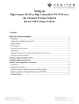
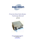
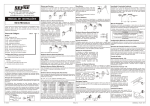
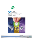
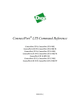
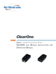
FireLine Ethernet
Radio Modem
Technical Manual
Version E1
March 2007
Raveon Technologies Corporation
2780 La Mirada Dr. Suite C
Vista, CA 92081
760-727-8004
www.raveontech.com
Powered By:
FireLine System Protocol Manual
1
Raveon Technologies Corp.
Table of Contents
1.
2.
Overview........................................................................................................3
Digi Connect ME............................................................................................5
2.1.
2.2.
2.3.
2.4.
Documentation............................................................................................................................. 5
Security Features......................................................................................................................... 6
The Default Web Interface ........................................................................................................... 6
Using the Digi Discovery Program ............................................................................................... 6
Open the Web Interface...................................................................................... 7
By Entering the Device’s URL in a Web Browser ............................................... 7
2.5.
3.
User Interfaces............................................................................................................................. 7
Configuring the Ethernet Interface .................................................................7
3.1.
Assigning an IP Address to the FireLine ...................................................................................... 7
Prerequisites....................................................................................................... 8
Procedure ........................................................................................................... 8
3.2.
Enable or Disable Network Services............................................................................................ 9
Network Services that Can Be Enabled or Disabled........................................... 9
4.
Telnet Operation ..........................................................................................10
4.1.
4.2.
5.
RealPort Virtual COM port ...........................................................................13
5.1.
5.2.
5.3.
5.4.
6.
RealPort Software...................................................................................................................... 13
Encrypted RealPort.................................................................................................................... 14
Creating a Virtual Port................................................................................................................ 14
Quick Test of Virtual COM port .................................................................................................. 15
TCP/IP Socket Operation ............................................................................16
6.1.
6.2.
7.
About TCP and UDP Port Numbers........................................................................................... 10
Configuring the FireLine Ethernet for Telenet Operation ........................................................... 10
About TCP and UDP Port Numbers........................................................................................... 16
Configuring the FireLine TCP Socket Operation........................................................................ 16
Important Safety Information........................................................................18
FireLine System Protocol Manual
2
Raveon Technologies Corp.
1. Overview
The FireLine Ethernet radio modem combines two products in one unit. It is a
FireLine radio modem, with all of the features and functions of Raveon’s FireLine
series of radio modems, along with a Digi Connect Ethernet interface.
The FireLine Ethernet radio modem has two user I/O ports. Either one or both
may be used to send and receive data over the radio channel. Data from both
ports is sent over the air, and all data received over the air will come out both
ports.
The serial port is a standard RS-232 serial port, which operates the same on all
FireLine radio modems. It can be used to send/receive data or to manage the
configuration.
The 10./100 Ethernet interface supports many different network protocols. Your
application will dictate which is the best mode to use. If you would like
assistance in choosing the best protocol, contact Raveon Application Support to
discuss which is best for you. Available Protocols are:
•
•
•
•
Telnet
Realport COM port emulation.
Udpserial
TCP Sockets
FireLine System Protocol Manual
3
Raveon Technologies Corp.
All Ethernet functions are implemented using the embedded Digi Connect ME1
module within the FireLine Ethernet radio modem. This module is made by Digi
International, Inc. of Minnetonka, Minnesota a division of NetSilicon. The Digi
Connect ME interface is built on leading 32-bit ARM technology using the
network-attached NetSilicon NS7520 microprocessor, the Digi Connect ME
combines true plug-and-play functionality.
The most straightforward method to implement the FireLine Ethernet is the “COM
Port Redirection” technique, using Realport software. The FireLine Ethernet uses
the patented RealPort COM/TTY port redirection for Microsoft Windows, UNIX,
and Linux environments. RealPort software provides a virtual connection to serial
devices, no matter where they reside on the network. The software is installed
directly on the host and allows applications to talk to devices across a network as
though the devices were directly attached to the host on a COM port.
In the system above, any application running on the system computer will talk
over the RF link as if it were a COM serial port on the PC. In most of these types
of applications, the user’s application software needs no customization. It simply
communicates to a COM port, and thinks the FireLine Ethernet is plugged into a
serial port on the system PC.
FireLine Ethernet modems may be used in radio networks with other FireLine
Ethernet modems, or with standard RS232/RS485 FireLine modems, effectively
connecting the System PC/Device to a remote serial port, via the wireless link as
shown below.
1
Connectware, Digi Connect EM, Digi Connect ME, Digi Connect SP, Digi Connect Wi-EM, and Digi Connect Wi-ME are
trademarks of Digi International, Inc.
FireLine System Protocol Manual
4
Raveon Technologies Corp.
2. Digi Connect ME
The Digi Connect ME module is the Ethernet interface used within the FireLine
Ethernet radio modem. The following sections provide an overview of its
capabilities. Please refer to the appropriate Digi Connect ME documentation for
details on its capabilities.
2.1.
Documentation
The advanced features in the FireLine Ethernet are implemented in the Digi
Connect Ethernet interface module used within the product. This manual covers
an abbreviated version of the Digi Connect documentation and is suitable to use
to configure the Virtual COM port and Telnet functions of the product. For other
features, consult the appropriate Digi documentation included on the CD that
came with your FireLine Ethernet. They are also available on the Digi web site at
http://www.digi.com/ (>Support >Documentation) The Digi Connect documents
are:
Digi Connect Family Command Reference
Realport Installation Guide
Digi Connect User’s Guide
RCI Specification
The FireLine Ethernet modem has all the features of a standard FireLine radio
modem, and is configured in the same way as an RS232 FireLine. Refer to
Raveon’s FireLine MODEM Technical Manual for information on how to
configure all radio modem parameters such as frequency, data rates, and
diagnostics. This is available at: http://www.raveontech.com/Manuals/RVM5_Tech_Manual.pdf .
FireLine System Protocol Manual
5
Raveon Technologies Corp.
2.2.
Security Features
Network recurity-related features in Digi Connect devices include:
•
Secure access and authentication:
•
One password, one permission level. (Default user: root Default password: dbps )
•
Can issue passwords to device users.
•
Can selectively enable and disable IP services: network services such as ADDP,
RealPort, Encrypted RealPort, HTTP/HTTPS, LPD, Remote Login, Remote Shell,
SNMP, and Telnet, can be enabled and disabled.
Secure sites for configuration: HTML pages for configuration have appropriate
security.
•
•
•
•
•
2.3.
Encryption: Digi Connect devices include strong Secure Sockets Layer
(SSL) V3.0/
Transport Layer Security (TLS) V1.0-based encryption: DES (56-bit),
3DES
(168-bit), AES (128-/156-bit): Encrypted RealPort offers encryption for the
Ethernet connection between the
COM/TTY port and the Digi Connect device: Wireless Digi Connect
devices provide Wi-Fi Protected Access (WPA) and
SNMP security: Authorization: Changing public and private community
names is recommended to prevent unauthorized access to the device.
You can disable SNMP set commands to make use of SNMP read-only.
The Default Web Interface
A default web interface is provided as an easy way to configure and monitor Digi
Connect devices like the FireLine Ethernet modem. Configurable features are
grouped into several categories: Network, Serial Port, Alarms, Security, and
System. Most of the configurable features are arranged by most basic settings on
a page, with associated and advanced settings accessible from that page. As in
the Digi Device Setup Wizard, serial port configurations are classified into port
profiles, or configuration scenarios that allow you to select the scenario that best
represents the environment and set up the appropriate parameters that are
needed.
When configuring some features, you may want to establish a basic configuration
using the Digi Device Setup Wizard, and then fine-tune the configuration using
the default web interface.
2.4.
Using the Digi Discovery Program
The Digi Discovery Program is the preferred method of managing your FireLine
Ethernet products. It is an easy-to-use program that displays all Digi powered
devices, and with a few clicks, allows you to configure them. When you run the
Digi Discovery program called “dgdiscvr.exe”, the program will search for all Digi
devices, and display a list of them on your screen.
FireLine System Protocol Manual
6
Raveon Technologies Corp.
Note: When power is first applied to the Ethernet FireLine, it may take the Digi
Connect module up to 30 seconds to boot-up, and begin normal communications
on the network.
Open the Web Interface
To open the default web interface, you can either:
•
•
Enter the Digi Connect device’s URL in a Web browser and log on to the device, if required.
Use the Digi Device Discovery utility to locate the device and open the Web interface.
By Entering the Device’s URL in a Web Browser
In the URL address bar of a Web browser, enter the IP address of the device. If
security has been enabled for the device, a login dialog will be displayed. Enter
the user name and password for the device. If you do not know the user name
and password for the device, contact the system administrator who initially set up
the device.
After you log on, the Home page of the default web interface is displayed and
you are ready to configure the Ethernet interface on the FireLine
2.5.
User Interfaces
FireLine Ethernet data radios with the Digi Connect device support a variety of
user interfaces for configuring and monitoring tasks, including:
•
•
•
•
•
•
The Digi Device Setup Wizard
A default web-based interface (Preferred)
An optional Java-applet interface
Telnet Command-Line Interface
Configuration via Remote Command Interface (RCI) over the serial port
Simple Network Management Protocol (SNMP)
3. Configuring the Ethernet Interface
3.1.
Assigning an IP Address to the FireLine
There are several ways to assign an IP address to a FireLine Ethernet:
•
•
•
•
Using the Digi Device Setup Wizard.
Using Dynamic Host Configuration Protocol (DHCP) from the default web
interface (only for changing the IP address once it has been assigned).
Using the Command-Line Interface.
Using Automatic Private IP Addressing (APIPA), also known as Auto-IP.
This section describes how to configure the device with the Digi Setup Wizard.
To use the other methods, refer to the “Digi Connect Family User Guide”
supplied on the CD with your FireLine Ethernet modem.
FireLine System Protocol Manual
7
Raveon Technologies Corp.
Using the Digi Device Setup Wizard is the preferred method of assigning an IP
address and initially configuring your Digi Connect device. The Digi Device Setup
Wizard is supplied on the CD that accompanies your Digi Connect device.
The Digi Device Setup Wizard “discovers” the device, and then provides a
method for assigning an IP address as well as configuring your device for your
needs. It can be used in conjunction with the web interface to ‘tweak’ the specific
environment. Setup is specially designed for the Windows environments, and is
quick, automated, and complete.
Prerequisites
This procedure assumes the following:
•
•
•
•
•
•
The FireLine Ethernet device is connected to the network and powered up.
The CD will be used on a system running Microsoft Windows operating system
or a Unix operating system.
That you have located the device server’s MAC address, located on the label on
the bottom of the product, and recorded it for later use in assigning an IP
address.
Procedure
1. Insert the Digi CD in the CD drive.
2. If the CD does not start automatically, double-click My Computer > CD
ROM Drive > setup.exe
3. The Digi Device Setup Wizard will automatically pop up. Select your
platform and click Next.
4. The Digi application finds and lists all of the Digi devices on your network.
5. Locate your device server by its MAC address.
6. Select the device server and then click Next.
7.
Follow the instructions in the wizard to configure your Digi Connect device.
The default user is: root The default password is: dbps Use the online
help supplied with the wizard if you need more information about values
the wizard prompts you to supply and select.
The main configure menu for setting the IP address in the FireLine Ethernet will
look like the screen snapshot below. In this example, the FireLine Ethernet is
configured with a static IP address.
FireLine System Protocol Manual
8
Raveon Technologies Corp.
3.2.
Enable or Disable Network Services
The Network Services page shows a set of common network services that are
available for devices, and the port on which the service is running.
You can enable or disable several common network services and configure the
TCP port they listen on. Disabling services may be done for security purposes.
That is, you can disable certain services so that a device is running only those
services specifically needed by the device. As needed, you can also disable any
non-secure services, such as Telnet.
Network Services that Can Be Enabled or Disabled
Following are the network services which can be enabled or disabled. By default,
all services are ENABLED.
•
ADDP: This service controls use of Advanced Digi Device Discovery Protocol. If it is
disabled, you can no longer use the Digi Device Setup Wizard, or Digi Device
Discovery utility to locate the device.
•
HTTP & HTTPS: These services control the use of the Web interface. If you disable them,
device users cannot use the default web interface or Java applet to configure,
monitor, and administer the device.
•
RealPort or Encrypted RealPort: These services control use of COM port redirection. If
disabled, COM port redirection cannot be used for the device.
•
Rlogin: Enables or disables the remote login (rlogin) service. If disabled, users cannot
perform a remote login to the device.
•
Rsh: Enables or disables the remote shell (rsh) service.
FireLine System Protocol Manual
9
Raveon Technologies Corp.
•
SNMP: Enables or disables the use of SNMP. If disabled, SNMP services such as traps
and device information are not used.
•
Telnet: Enables or disables the Telnet service. If disabled, users cannot Telnet to the to the
device.
4. Telnet Operation
FireLine Digi Connected devices support the following types of Telnet
connections:
•
Telnet Client
•
Telnet Server
•
Reverse Telnet, often used for console management or device management
•
Telnet Autoconnect
•
RFC 2217 (Telnet Com Port Control Option)
For more information on these connections, see the section "Supported
Connections and Data Paths" in the Digi Connect Family User’s Guide.
Access to Telnet network services can be enabled or disabled.
Note: When the FireLine Ethernet with Digi Connect is first powered on, it may
take up to 30 seconds to boot-up, and begin normal communications on the
network interface.
4.1.
About TCP and UDP Port Numbers
Digi Connect devices use the following default TCP and UDP port numbering
conventions described in the following table: You must ensure that the
application or device that initiates communication with the Connect device uses
these ports. If they cannot be configured to use these ports, you change the
individual network port on the Digi Connect device, which allows you different
port numbers to designate a Telnet or raw connection to the serial port.
For this connection type... Use these ports:
•
•
•
4.2.
Standard Unencrypted Telnet, port 23.
Telnet to the seria,l port 2001 (TCP only)
Raw connection to the serial, port 2101(TCP and UDP)
Configuring the FireLine Ethernet for Telenet Operation
This procedure assumes the IP address of the FireLine Ethernet radio modem
has already been set, as per the previous section.
1. Using the Digi Connect Discovery program, select and log into your FireLine
Ethernet modem’s web interface.
FireLine System Protocol Manual
10
Raveon Technologies Corp.
2. From the main menu, select “Serial Ports”. This will display the current serial
port configuration as shown below.
3. Click on Port1, to display its configuration. The port profile shoul dbe “Console
Management” as shown below. If it does, skip to step 5, if not, perform step 4.
4. If the port is not in Console Management profile, click on “Change Profile, and
select “Console Management” and press “Apply”.
5. Click on “Basic Serial Settings” on the bottom of the Serial Port Configuration
screen. Set the serial port parameters as shown below and press “Apply”.
The baud rate must be 57600bps, as that is the internal serial port baud rate
that the FireLine’s modem uses to communicates with the Digi Connect
FireLine System Protocol Manual
11
Raveon Technologies Corp.
module.
6. Select Network Configuration
and then “Network Services Settings
FireLine System Protocol Manual
12
Raveon Technologies Corp.
7. In Network Service Settings, highlight only the service you wish to use. For
Telenet, the minimum recommended is: ADDP, Telnet, and HTTP.
The FireLine Ethernet is now ready to use as a Telnet server. To log into the
FireLine Ethernet, open up any telenet program, and connect to the IP address of
the FireLine Ethernet using port 23. Login with the user name and password.
The default user is: root The default password is: dbps.
Use the “Connect 1” command to connect to the FireLine. Once connected, all
characters from the Telnet session will pass directly to the FireLine and be sent
over the air. All over the air data will be directed to the Telnet application.
5. RealPort Virtual COM port
5.1.
RealPort Software
The FireLine Ethernet uses the patented RealPort COM/TTY port redirection for
Microsoft Windows, UNIX, and Linux environments. RealPort software provides a
virtual connection to serial devices, no matter where they reside on the network.
The software is installed directly on the host and allows applications to talk to
devices across a network as though the devices were directly attached to the
host. Actually, the devices are connected to a Digi device server or terminal
server somewhere on the network.
RealPort is unique among COM port re-directors because it is the only
implementation that allows multiple connections to multiple ports over a single
TCP/IP connection. Other implementations require a separate TCP/IP connection
or each serial port. Unique features also include full hardware and software flow
control, as well as tunable latency and throughput.
FireLine Ethernet devices with the Digi Connect module support RFC 2217, an
extension of the Telnet protocol used to access serial devices over the network.
FireLine System Protocol Manual
13
Raveon Technologies Corp.
RFC 2217 implementations enable applications to set the parameters of remote
serial ports (baud rate, flow control, etc.), detect line signal changes, as well as
receive and transmit data. The configuration information provided in this section
applies to devices functioning as RFC 2217 servers.
Access to RealPort services can be enabled or disabled.
Note: When the FireLine Ethernet with Digi Connect is first powered on, it may
take up to 30 seconds to boot-up, and begin normal communications as a virtual
COM port.
5.2.
Encrypted RealPort
Encrypted RealPort offers a secure Ethernet connection between the COM or
TTY port and a device server or terminal server. Encryption prevents internal and
external snooping of data across the network by encapsulating the TCP/IP
packets in a Secure Sockets Layer (SSL) connection and encrypting the data
using Advanced Encryption Standard (AES), one of the latest, most efficient
security algorithms.
Digi’s RealPort with encryption driver has earned Microsoft’s Windows Hardware
Quality Lab (WHQL) certification. Drivers are available for a wide range of
operating systems, including Microsoft Windows Server 2003, Windows XP,
Windows 2000, Windows NT, Windows 98, Windows ME; SCO Open Server;
Linux; AIX; Sun Solaris SPARC; Intel; and HP-UX. It is ideal for financial,
retail/point-of-sale, government or any application requiring enhanced security to
protect sensitive information.
5.3.
Creating a Virtual Port
1. Install the provided Digi Connect software on the PC that will have the virtual COM port.
2. Connect the FireLine Ethernet device to the network.
3. Apply power to the FireLine Ethernet modem. The Ethernet connector has two LEDs
located near the RJ-45 connector. The amber LED should be illuminated indicating the
device is powered ON and connected to the network. The green LED will flicker when the
device detects network traffic.
4. Assign the Digi Connect device an IP address using the device discovery program. See
the section of this manual “Configuring the Ethernet Interface” for details on how to set
the IP address of the FireLine Ethernet.
5. Configure the FireLine Ethernet module for RealPort virtual COM port using the Digi
Device Discovery program.
a. Start > All Programs > Digi Connect > Digi Device Discovery
b. You should see a list of Digi Connect devices listed in the window.
c.
Select the desired Digi Connect device from the window listing.
d. Select Open Web Interface in the Device Tasks window.
e. User Name: root
f. Password: dbps
FireLine System Protocol Manual
14
Raveon Technologies Corp.
g. Select Serial Ports in the Configuration menu.
h. Select Port 1 under Serial Port configuration.
i.
Select the RealPort port profile and click the apply button. It is not necessary to
configure basic serial port settings since they will be set by the application
running the real port driver.
6. Install the RealPort driver on the PC that will be communicating with the
FireLine Ethernet. These drivers are included in the “realport” directory on
the CD supplied with your FireLine Ethernet.
a. Start > All Programs > Digi Connect > RealPort Drivers
b. Select the appropriate folder for your PC’s operating system.
c.
Run the Setup Application. The Setup Wizard will display all the Digi Connect
devices currently connected to the network.
d. Highlight the desired device and select the Next button. If you’re unsure about
which is the correct device, the MAC address is displayed on the serial number
label of the FireLine Ethernet device .
e. Select a COM port to use as the virtual communication port. The select the Next
button. Remember this is a virtual port, not an actual port on the PC, so select a
port other than those available on the PC.
5.4.
Quick Test of Virtual COM port
A communication program such as HyperTerminal may be used to test the
FireLine’s virtual COM port configuration. On the PC that is configured with the
Virtual COM port, open HyperTerminal.
Configure HyperTerminal to communicate with the FireLine modem using the
Virtual COM port.
Important! SET the baud rate to 57600bps.
FireLine System Protocol Manual
15
Raveon Technologies Corp.
The FireLine expects the virtual COM port baud rate to be set at 57600.
You should now be able to communicate with the FireLine Ethernet through the
virtual COM port as though it was connected directly to your PC’s COM port.
Characters typed into HyperTerminal will be transmitted over the air, and you can
enter the FireLine configuration mode by typing +++ in the same way you can
had the PC been connected using an RS-232 cable.
6. TCP/IP Socket Operation
FireLine Ethernet devices with the Digi Connect module support data transfer
using a TCP/IP socket.
6.1.
About TCP and UDP Port Numbers
Digi Connect devices use the following default TCP and UDP port numbering
conventions described in the following table: You must ensure that the
application or device that initiates communication with the Connect device uses
these ports. If they cannot be configured to use these ports, you change the
individual network port on the Digi Connect device, which allows you different
port numbers to designate a Telnet or raw connection to the serial port.
For this connection type... Use these ports:
•
•
Telnet to the serial port 2001 (TCP only)
Raw connection to the serial port 2101(TCP and UDP)
6.2.
Configuring the FireLine TCP Socket Operation
This procedure assumes the IP address of the FireLine Ethernet radio modem
has already been set, as per the previous section.
1. Using the Digi Connect Discovery program, select and log into your
FireLine Ethernet modem’s web interface.
2. From the main menu, select “Serial Ports”. This will display the current
serial port configuration as shown below.
8. Click on Port1, to display its configuration. The Port Profile should be “TCP
Sockets” as shown below. If it does, skip to step 5, if not, perform step 4.
FireLine System Protocol Manual
16
Raveon Technologies Corp.
9. If the port is not in TCP Socket profile, click on “Change Profile, and select
“TCP Sockets” and press “Apply”.
10. Click on “Basic Serial Settings” on the bottom of the Serial Port Configuration
screen. Set the serial port parameters as shown below and press “Apply”.
The Basic port setting for the baud rate must be 57600 for the FireLine
Ethernet.
11. Select Network Configuration
and then “Network Services Settings
FireLine System Protocol Manual
17
Raveon Technologies Corp.
The only Network Services that should be enabled are TCP sockets are
ADDP and HTTP.
The FireLine Ethernet is ready to operate using a TCP Socket. To test it, you
can use a Telnet program. Open a telnet session, using port 2101. There will be
no login prompt. Simply type characters in the telnet window, and the FireLine
Ethernet wills send them over the air. All data received over-the-air will be
transferred over the network to the Telnet program.
7. Specifications
Standard: .................................................................. IEEE 802.3
Physical Layer: ..................................................... 10/100Base-T
Data Rate: ....................................... 10/100Mbps (auto-sensing)
Mode: .......... Half-duplex and full-duplex support (auto-sensing)
Connector: ......................................................................... RJ-45
FireLine System Protocol Manual
18
Raveon Technologies Corp.
8. Important Safety Information
To avoid contact with electrical current:
•
•
•
•
•
•
•
•
•
•
•
•
•
•
Never install electrical wiring during an electrical storm.
Never install an Ethernet connection in wet locations unless that connector
is specifically designed for wet locations.
Use caution when installing or modifying Ethernet lines.
Use a screwdriver and other tools with insulated handles.
You and those around you should wear safety glasses or goggles.
Do not place Ethernet wiring or connections in any conduit, outlet or
junction box containing electrical wiring.
Installation of inside wire may bring you close to electrical wire, conduit,
terminals and other electrical facilities. Extreme caution must be used to
avoid electrical shock from such facilities. You must avoid contact with all
such facilities.
Ethernet wiring must be at least 6 feet from bare power wiring or lightning
rods and associated wires, and at least 6 inches from other wire (antenna
wires, doorbell wires, wires from transformers to neon signs), steam or hot
water pipes, and heating ducts.
Do not place an Ethernet connection where it would allow a person to use
an Ethernet device while in a bathtub, shower, swimming pool, or similar
hazardous location.
Protectors and grounding wire placed by the service provider must not be
connected to, removed, or modified by the customer.
Do not touch uninsulated Ethernet wiring if lightning is likely!
External Wiring: Any external communications wiring you may install
needs to be constructed to all relevant electrical codes. In the United
States this is the National Electrical Code Article 800. Contact a licensed
electrician for details.
Do not touch or move the antenna(s) while the unit is transmitting or
receiving.
FireLine System Protocol Manual
19
Raveon Technologies Corp.