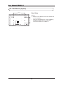
1
Philips
Business
Solutions
E
User Manual
G
Benützersanleitung
I
Guida Utente
S
Manual de uso
F
Manuel de l’utilisateur
TYPE NR.
BDH5011
User Manual BDH5011
Table of Contents
1.
2.
3.
4.
5.
IMPORTANT SAFETY INSTRUCTIONS . .3
FCC STATEMENT . . . . . . . . . . . . . . . . . . . .5
CLEANING AND MAINTENANCE . . . . . . .6
PRODUCT FEATURES . . . . . . . . . . . . . . . .8
PACKAGE CONTENTS . . . . . . . . . . . . . . .10
6. UNDERSTANDING YOUR DISPLAY
6.1 Front View . . . . . . . . . . . . . . . . . . . . . .
6.2 Rear View . . . . . . . . . . . . . . . . . . . . . .
6.3 Full-Function Remote Control . . . . . .
.
.
.
.
.
.
.
.
.
.
.
.
.
.
.
.
.
.
.
.
.12
.12
.12
.13
7. CONNECTING THE DISPLAY . . . . . . . . . . .15
7.1 Connecting a DVD Player . . . . . . . . . . . . . . . .15
7.2 Connecting a HDTV Decoder Set-Top Box . .16
7.3 Connecting a VCR . . . . . . . . . . . . . . . . . . . . . .17
7.4 External Audio Connections . . . . . . . . . . . . . 17
7.5 Connecting a PC . . . . . . . . . . . . . . . . . . . . . .19
7.6 RS-232 Remote Control Connections . . . . . . 20
8. USING YOUR DISPLAY - BASICS
8.1 Powering ON / OFF . . . . . . . . . . . .
8.2 Selecting Signal Source . . . . . . . . . .
8.3 Adjusting Sound Volume . . . . . . . . .
.
.
.
.
.
.
.
.
.
.
.
.
.
.
.
.
.
.
.
.
.
.
.
.
.
.
.
.
.23
.23
.24
.25
9. USING WITH HDTV . . . . . . . . . . . . . . . . . . .26
9.1 Understanding HDTV . . . . . . . . . . . . . . . . . . 26
10. ADVANCED FUNCTIONS . . . . . . . . . . . .
10.1 Picture-In-Picture (PIP) / Side-by-Side Picture (POP) .
10.2 Widescreen (16:9 Aspect Ratio) Viewing Modes
10.3 On-Screen Display (OSD) Settings . . . . . . . .
10.4 Sleep Timer Settings . . . . . . . . . . . . . . . . . . .
10.5 Variable and Fixed Audio Output . . . . . . . . .
10.6 Sound Adjustments . . . . . . . . . . . . . . . . . . . .
10.7 Inner Speaker ON/OFF . . . . . . . . . . . . . . . . .
10.8 Signal Frequency Information Display . . . . . .
.28
.28
.32
.34
.35
.36
.36
.37
.38
11. PICTURE ADJUSTMENT . . . . . . . . . . . . . . .40
11.1 For AV/Component Video (480i signal) . . . . . . .40
11.2 For Component Video (480p, 720p and 1080i . . .
signal) . . . . . . . . . . . . . . . . . . . . . . . . . . . . . . .42
11.3 For Component Video (480p, 720p and 1080i
signal) Con’t . . . . . . . . . . . . . . . . . . . . . . . . . . .44
11.4 For RGB/DVI . . . . . . . . . . . . . . . . . . . . . . . . . .45
12. TROUBLESHOOTING . . . . . . . . . . . . . . . . .47
13. SPECIFICATIONS . . . . . . . . . . . . . . . . . . . . .48
14. WALL MOUNT (OPTION) . . . . . . . . . . . . 56
2
User Manual BDH5011
1. Important Safety Instructions
WARNING
RISK OF ELECTRIC SHOCK
DO NOT OPEN
The lightning flash with arrow-head within a
triangle is intended to inform the user that parts
inside the product are a risk of electric shock.
WARNING
To reduce the riskofelectricshock, do not
remove the front or back covers.
No user-serviceable parts inside. Refer servicing
to qualified service personnel only.
The exclamation point within a triangle
is intended to tell the user that important
operating and servicing instructions are
explained.
WARNINGS & PRECAUTIONS
• To prevent damage which may result in fire
or shock hazard, do not expose this product
to rain or moisture.
• To prevent electric shock, do not remove
cover. No user serviceable parts are inside.
Refer servicing to qualified service personnel
only.
• Keep display away from excessive dust, high
temperatures, moisture or direct sunlight.
• Use in a well-ventilated area and do not
cover ventilation openings.
• Unauthorized modification of this equipment
or usage of an unshielded connecting cable
may cause excessive interference.
• When the display is not in use for a long
period of time, disconnect it from the
electric outlet.
• If the picture displayed is in any way
abnormal, turn off the unit and disconnect it
from the electric outlet.Verify your signal
wire connections and reconnect the display
to the electric outlet.
• Disconnect from the electric outlet before
cleaning. Do not use liquid or aerosol
cleaners. Use only a slightly damp cloth for
cleaning.
• Do not place this product on an unstable
cart, stand or table.The product may fall,
causing serious damage.
• Do not place the unit on a bed, sofa, rug, or
other similar surfaces. Never place the unit
near or over a radiator or heat source.
3
User Manual BDH5011
Do not install unit in an enclosed area unless
proper ventilation is provided.
• The unit should be operated from the type
of power source indicated on the label. If the
type of available power is unknown, consult
your dealer or local power company.
• The unit is equipped with a 3-pin grounded
plug.The plug will only fit into a grounded
power outlet.This is a safety feature. If you
are unable to insert the plug into the outlet,
contact your electrician. Do not alter the
plug; this will defeat the safety feature.
• Do not rest objects on the power cord &
avoid placing power cord near high traffic
areas.
• Do not overload wall outlets and extension
cords as this can result in a risk of fire or
electric shock.
• Disconnect the unit from the main supply
and refer servicing to qualified service
personnel under the following conditions:
• Power cord or plug is damaged or frayed.
• Liquid has been spilled into the product.
• Unit has been exposed to water or
moisture.
• Unit does not operate normally when the
operating instructions are followed. Adjust
only those controls that are covered by
the operating instructions, improper
adjustment of other controls may result in
damage which often requires extensive
work by a qualified technician to restore
the unit to normal operation.
• Unit has been dropped or the cabinet has
been damaged.
• Unit exhibits a distinct change in
performance, indicating a need for service.
4
User Manual BDH5011
2. FCC Statement
FCC Compliance Statement
The equipment has been tested and found to
comply with the limits for a Class B digital
device, pursuant to part 15 of FCC rules.
These limits are designed to provide reasonable
protection against harmful interference when the
equipment is operated in a commercial
environment.
This equipment generates, uses, and can radiate
radio frequency energy and, if not installed and
used in strict accordance with the instruction
manual, may cause harmful interference to radio
communications.
There is no guarantee that interference will not
occur in a particular installation. If this
equipment does cause harmful interference to
radio or television reception, which can be
determined by turning the equipment off and on, the user is encouraged to try
to correct the interference by one or more of
the following measures:
• Reorient or relocate the receiving antenna.
• Increase the separation between the
equipment and the receiver.
• Connect the equipment into an outlet on a
circuit different from that to which the
receiver is connected.
• Consult the dealer or an experienced
radio/TV technician for help.
Operation of this equipment in a residential area
is likely to cause harmful interference in which
case the user will be required to correct the
interference at the owner’s expense.
Shielded interconnected cables and shielded
power cords must be employed with this
equipment to insure compliance with the
pertinent RF emission limits governing this
device.
Changes or modifications not expressly
approved by the manufacturer could void the
user's authority to operate the equipment and
void the warranty.
Canadian Compliance Statement
This Class B digital apparatus meets all
requirements of the Canadian Interference
Causing Equipment Regulations.
Cet appareil numérique de la Classe B respecte
toutes les exigences du Règlement sur le
matériel brouilleur du Canada.
5
User Manual BDH5011
3. Cleaning and Maintenance
Cautions When Using the Plasma Display
• Do not bring your hands, face or objects
close to the ventilation holes of the plasma
display.Top of plasma display is usually very
hot due to the high temperature of exhaust
air being released through the ventilation
holes. Burns or personal injuries may occur if
any body parts are brought too close. Placing
any object near the top of the display could
also result in heat related damages to the
object as well as the display itself.
• Be sure to disconnect all cables before
moving the plasma display. Moving the display
with its cables attached may damage the
cables, and thus, cause fire or electric shock
danger.
• Disconnect the power plug from the wall
outlet as a safety precaution before carrying
out any type of cleaning or maintenance
procedure.
Front Panel Cleaning Instructions
• The front of the display has been specially
treated.Wipe the surface gently using only a
cleaning cloth or a soft, lint-free cloth.
• If the surface is particularly dirty, soak a soft,
lint-free cloth in a mild detergent solution.
Wring the cloth to remove excess liquid.
Wipe the surface of the display to remove
dirt.Then use a dry cloth of the same type
to dry.
• Do not scratch or hit the surface of the
panel with fingers or hard objects of any
kind.
• Do not use volatile substances such as insect
sprays, solvents and thinners.
Cabinet Cleaning Instructions
• If the cabinet becomes dirty, wipe the
cabinet with a soft, dry cloth.
• If the cabinet is extremely dirty, soak a lintfree cloth in a mild detergent solution.Wring
the cloth to remove as much moisture
possible.Wipe the cabinet. Use another dry
cloth to wipe over until the surface is dry.
• Do not allow any water or detergent to
come into contact with the surface of the
display.
If water or moisture gets inside the unit,
operating problems, electrical and shock
hazards may result.
• Do not scratch or hit the cabinet with
fingers or hard objects of any kind.
6
User Manual BDH5011
• Do not use volatile substances such as insect
sprays, solvents and thinners on the cabinet.
• Do not place anything made from rubber or
PVC near the cabinet for extended periods
of time.
Avoid Still Images
• Do not allow a still picture to be displayed
for extended periods of time.This can cause
a permanent image to remain on the plasma
display. Examples of still images may include:
still computer images, still video game
images, still logos or pictures, text and
images displayed in 4:3 Normal mode.
Contents of this manual is subject to
change without notice.
Trademark Credits
• VGA is a trademark of IBM Corporation.
• Macintosh is a registered trademark of Apple
Computer Corporation.
• SVGA is a registered trademark of the Video
Electronics Standard Association.
• All other trademarks are the properties of
their respective owners.
7
User Manual BDH5011
4. Product Features
• Advanced Digital Image Processing
Advanced digital processor with adaptive
motion de-interlacing converts all 15KHz
signals into progressive scan for a brighter,
flicker free image.
• Pull-Down for Film Scan Conversion
Built-in 3:2 pull-down processing can
automatically detect and convert film
content to properly display with minimal
motion artifacts.
• 3D Comb Filter
Built-in 3D comb filter converts analog signal
into a digital signal for more accurate
processing, eliminating cross-color
interference for superior NTSC video
performance.
• Dual HD Component Video Inputs
Two high-definition component video inputs
with auto-detection capabilities will
automatically synchronize the display to
match the incoming signal source without
manual intervention.
• Picture-in-Picture (PIP)
Watch two programs simultaneously using
the display’s picture-in-picture with four
selectable window position settings.
• Side-by-Side Picture (POP)
Watch two programs simultaneous by
splitting the screen in half.
• HDTV Signal Compatible
This display is capable of accepting 1080i and
720p HDTV signals via an external HDTV
decoder with RGB or Component Video
outputs.
• Digital Zoom Modes
Digital zoom modes gets rid of black bars
common to non-16:9 aspect ratio movie
content.
• DVI Digital Video Interface with HDCP
(High-Bandwidth Digital Content
Protection Protocol)
Standard DVI interface supports the lastest
in digital video peripherals equipped with
DVI HDCP digital video output(s).This
means that digital content can now passed
8
User Manual BDH5011
from sources such as a digital DVD player,
directly to this display without digital-toanalog conversion that erodes video quality.
Direct digital-to-digital connection ensures
the absolute best in video quality.
• 280x1024 SXGA Support
The onboard digital scaling engine can accept
various PC and HDTV signals and digitally
map the signals to fit within 1366 x 768
pixels.
• Discrete Power ON/OFF
Separate Power ON/OFF buttons on the
remote control facilitates the recording of IR
macros with advanced system setups.
• Direct Input Selection Keys
Separate input selection keys on the remote
control allows quick and easy selection of
various inputs.
• RS-232 Serial Connection
The RS-232 command set includes front
panel lock, input selection, power on/off,
volume and other standard RS-232 command
controls.
9
User Manual BDH5011
5. Package Contents
Supplied Accessories
Please verify that you received the following
items with your package content:
Plasma Display
Remote Control
User Manual
Power Cable
10
User Manual BDH5011
VGA Cable
Batteries
Optional Accessories
The following accessories are available and may
be purchased from your local sales
representative:
• Wall Mount
• Composite Video Cable (RCA)
• S-Video Cable (Mini-Din)
• Component Video Cable (RCA to RCA)
• Audio Cable (RCA Cable)
11
User Manual BDH5011
6. Understanding your Display
6.1 Front View
Power (Standby) Button
Turns power on/off from standby mode.
There is a 3-second wait between on/off cycles.
Status LED:
• Not Illuminated - No AC Power
detected
If the main power switch (rear of panel) is
turned off, this LED will not illuminate.
• Solid Yellow - Standby (Power OFF)
with AC power detected
The LED will illuminate in yellow color if the
display is shut-off but the main power cord is
plugged into the back of the unit.
• Solid Green - Power ON
• Input Button
Use this button to switch between available
inputs.
• Menu +/- Buttons
Use this menu to engage the On Screen
Display menu.
• Volume Adjustment +/- Buttons
Use these buttons to adjust volume up and
down.
These keys also serve as adjustment keys
when On Screen Display is engaged.
6.2 Rear View
RGB / COMPUTER RELATED CONNECTORS
RGB IN
RGB OUT
DVI IN
RS-232
VIDEO CONNECTORS
12
User Manual BDH5011
6.3 Full Function Remote Control
1
14
2
15
16
3
6
4
5
17
18
2. Number Keypad
These keys are not applicable to this
monitor.
3. QuickView
This key is not applicable to this monitor.
19
20
7
21
8
22
9
23
10
1. Standby Power On/Off
Push this button to turn on the display from
Standby mode. Push it again to turn off to
Standby mode.
4. PIP (Picture-in-Picture Button)
Turns on PIP (Picture-in-Picture) mode and
POP (Side-by-Side) picture mode.
(See Pages 17)
5. Favorite Channel
This key is not applicable to this monitor.
6. PIP/POP Source
Changes the input source of the PIP or POP
sub-window. (See Chapter 10)
11
12
13
7. Closed Captioning|
This key is not applicable to this monitor.
8. V-Chip
These keys are not applicable to this
monitor.
9. MTS Stereo
This key is not applicable to this monitor.
10. Channel Lock / Fav. Set
These keys are not applicable to this
monitor.
11. Sleep Timer
Engages Sleep Timer Settings. (See Page 21)
12. Discrete Power ON/OFF
Press OFF to send display into Standby
mode. Press ON to power on from standby
mode. (See Page ...)
13. Direct Input Selection Keys
Direct input change input signal selection by
pressing the appropriate key.
14. Sound Mute On/Off
15. Volume +/Turns volume up or down.
13
User Manual BDH5011
1
14
2
15
16
3
6
4
5
17
18
19
20
7
21
8
22
9
23
10
11
16. Channel Up/Down
These keys are not applicable to this
monitor.
17. Swap
This key swaps the main and sub picture
windows under PIP or POP modes.
(See chapter 10))
18. PIP Position
This key changes the PIP sub-window to 4
different corner locations. (See Chapter 10)
19. Input Select
Press to select input signal modes
sequentially. (See Chapter 8).
20. MENU Adjustment
1. Show OSD menu by pressing
or
key
or MENU key.
2. Scroll thru the major OSD category using
or
key.
3. Press the
or
keys again to select
sub-options within the category.
4. Press the
or
keys to change the
actual sub-option setting.
12
21. Recall
Recalls the default picture settings. (See
Chapter 11).
13
22. Display
Press to show the status of the display.
AV Mode (PIP/POP On)
AV1
Main Source
AV2
PIP/POP Source
PIP
Component Mode
COMPONENT 1
Main Source
1080I
Incomming Signal
RGB
Main Source
M:06
Display Mode
RGB Mode
23. Wide
Toggles between various aspect ratio
settings. (See Chapter 10).
14
User Manual BDH5011
7. Connecting the Display
7.1 Connecting a DVD Player
Using Component Video Input
1. Connect the green-colored (labeled as Y)
jack from the DVD to the green-colored Y1jack of the display
2. Connect the red-colored (labeled as PR or
CR) jack from the DVD to the red-colored
PR1/CR1 jack of the display.
3. Connect the blue-colored (labeled as PB or
CB) jack from the DVD to the blue-colored
PB1/CB1 jack of the display.
4. Connect the red (R) and white (L) audio
jacks from the DVD to the R and L audio-in
jacks located next to the PR1/CR1 connector.
Note:
There are two sets of component inputs
provided.You can use either set of
component inputs to connect your DVD.
Using S-Video Input
1. Connect the S-Video (4-pin DIN) connector
from the DVD to the S-VIDEO input on
the back of display.
2. Connect the red (R) and white (L) audio
jacks from the DVD to the R and L audio-in
jacks located next to the S-VIDEO connector.
Using Composite (AV) Video Input
1. Connect the yellow (video) connector from
the DVD to the yellow VIDEO 1 input on
the back of display.
2. Connect the red (R) and white (L) audio
jacks from the DVD to the R and L audio-in
jacks located next to the yellow VIDEO 1
connector.
15
User Manual BDH5011
7.2 Connecting a HDTV Decoder
Set-Top Box
Using Component Video Input
1. Connect the green (labeled as Y) jack from
the HDTV Set-top box to the green Y1 jack
of the display.
2. Connect the red (labeled as PR or CR) jack
from the HDTV Set-top box to the red
PR1/CR1 jack of the display.
3. Connect the blue (labeled as PB or CB)
jack from the HDTV Set-top box to the blue
PB1/CB jack of the display.
4. Connect the red (R) and white (L) audio
jacks from the HDTV Set-top box to the R
and L audio-in jacks located next to the
PR1/CR connector.
Note:
• Some HDTV Set-top boxes may not have a
Component Video output. Instead, use RGB
input method.
• There are two sets of component inputs
provided.
You can use either set of component inputs
to connect your HDTV Set- top box.
Using RGB Input
1. Connect the 15-pin D-Sub RGB connector
from the back of the HDTV Set-top box to
the RGB-IN connector located on the back
of the display.
2. Connect the red (R) and white (L) audio-out
jacks from the HDTV Set-top box to the R
and L audio-in jacks located to the left of the
S-VIDEO connector.
Note:
• Some HDTV Set-top boxes may not have a
RGB output. Use Component Video input
method if this is the case.
• Upon connecting your HDTV Set-top box to
the RGB input of the display, it may be
necessary to adjust various picture settings
on the display to correctly match the output
of the HDTV Set-top box. (See Chapter
Picture Adjustment).
This is caused by the different video timings
set by various HDTV Set-top box
manufacturers.
• This plasma supports 480p, 720p and 1080i
under RGB mode.
16
User Manual BDH5011
7.3 Connecting a VCR
Using S-Video Input
1. Connect the S-Video (4-pin DIN) connector
from the VCR to the S-VIDEO input on the
back of display.
2. Connect the red (R) and white (L) audio
jacks from the VCR to the R and L audio-in
jacks located next to the S-VIDEO
connector.
Using Composite Input
1. Connect the ihyellowlg (video) out
connector from the VCR to the yellow Video
1 input on the back of the display.
2. Connect the red (R) and white (L) audio-out
jacks from the VCR to the R and L audio-in
jacks located next to the yellow Video
connector.
7.4 External Audio Connections
Connecting External Amplified Speakers
1. This display can be connected to an external
set of amplified speakers using the AUDIO
OUT jacks located on the back of the
display. In addition, this display is equipped
with a small 3.5 mm phono style plug for
remote turn-on applications that will automatically send a remote turn-on/off signal to
the external amplified speakers.
2. Connect the red (R) and white (L) AUDIO
OUT jacks from right side of the connector
panel to the external amplified speaker.
3. As an option, you may use the remote turnon plug. Please note that not all external
amplified speakers can accept remote-turn
on signals.
Connecting to an External Amplifier
1. This display can be connected to an external
amplifier using the AUDIO OUT jacks
located on the back of the display. In
addition, this display is equipped with a small
3.5 mm phono style plug for remote turn-on
applications that will automatically send a
remote turn-on/off signal to the external
amplifier.
2. Connect the red (R) and white (L) AUDIO
OUT jacks from right side of the connector
panel to the external amplifier or receiver.
3. As an option, you may use the remote turnon plug. Please note that not all external
amplifiers can accept remote-turn on signals.
17
User Manual BDH5011
Using the Subwoofer Out
(Connecting a Subwoofer)
1. This display is equipped with a subwoofer
output for connecting to an external
amplified subwoofer.
2. Connect a RCA cable from the subwoofer
output jack to the external subwoofer.
Notes:
• The AUDIO OUT RCA jacks can be set to
either Fixed or Variable audio output levels.
Please see Chapter 10 for additional
explanation of this feature.
• The RCA subwoofer outputs frequencies
below 120Hz.The subwoofer will use the
same Fixed or Variable audio output setting
as AUDIO OUT RCA jacks.
• The 3.5mm phono/earphone output level is
always used for remote turn on/off
applications.
18
User Manual BDH5011
7.5 Connecting a PC Using RGB
or DVI Video Input
1. For most PC’s, connect the 15-pin D-Sub
RGB connector from the back of the PC to
the RGB-IN connector located on the back
of the display. If you have a PC that is
equipped with a DVI (Digital Visual Interface),
you may connect the PC DVI connector
from the back of the PC to the DVI-In
connector located on the back of the display.
2. Connect the red (R) and white (L) audio
jacks from the PC to the R and L jacks
located to the left of the S-VIDEO
connector. If you are using a DVI interface,
simply connect the (R) and (L) audio jacks to
the R and L jacks located to the left of the
VIDEO 1 connector.
Notes:
• Your PC may have audio jacks in the form of
a 3.5mm phono plug. If this is the case, you
will need to use a phono-plug to RCA
converter cable in order to connect audio.
• A RGB loop-out labeled iaRGB OutlB will
allow another RGB display to be connected.
The RGB loop-out will display the same
signal as the RGB In signal source.
• The physical display resolution is a maximum
of 1024x768 dots when aspect ratio is set to
4:3 and 1366x768 dots when set to 16:9
the PC’s display resolution exceeds these
maximums, the display will have to artificially
eliminate dots in order to fit within the
physical dot capability of the display;
therefore, it is possible that the display may
not be able to show details with adequate
clarity.
19
User Manual BDH5011
7.6 RS-232 Remote Control
Connections
RS-232 Serial Terminal Overview
This display is equipped with an RS-232 serial
terminal for using the display with computer
controls.The RS-232 serial terminal conforms to
the RS-232C interface specification.The
computer will require software application (such
as programming language software) which allows
the computer to send and receive control data
that can support the communications parameter
listed below.
5
1
9
6
RS-232
Communications Parameters
These parameters are required to setup
communications with the display.
Specification:
RS-232C
Sync Method:
Synchronous
Baud Rate:
9600 bps
Parity:
None
Character:
Length 8 Bits
Stop Bit:
1 Bits
Pin Layout for RS-232 Terminal
The RS-232C terminal pin layout are as follows:
Pin 1: Received Line Signal Detector (Data
Carrier Detect)
Pin 2: Received Data (RXD)
Pin 3: Transmit Data (TXD)
Pin 4: Data Terminal Ready (DTR)
Pin 5: Signal Ground
Pin 6: Data Set Ready (DSR)
Pin 7: Request To Send (RTS)
Pin 8: Clear To Send (CTS)
Pin 9: Ring Indicator
Basic Format for Command Parameters
In order to transmit data from the computer to
the display, the data must be sent in 1-byte-hex
format.
The command code (see table below) must first
be sent to the display, followed by the desired
value setting in hexadecimal format.
The following is an example of a sequence to
change the displays input to RGB:
Step 1: Send 1-byte for command 91 (input
select) to the display in hex format 0x91
Step 2: Send 1-byte for the value of the RGB
input. In this example, send 0x06.
Step 3: The display will then respond back to
the PC with a 1-byte value to confirm
the setting.
20
User Manual BDH5011
Notes:
• To connect a PC to the display’s RS-232
port,You must use a isstraight-throughl• RS232 cable where pins 2 (RX) and 3 (TX) are
not reversed at one end.
• If there are no data to be sent, then the
parameter signal does not need to be sent.
• If multiple commands are transmitted, make
sure to wait for the response for the first
command to come from the display before
sending the next command.The following are
response command
signals:
RESPONSE: 80 70 = MODE ERROR
80 71 = TEM ERROR
80 72 = FORMAT ERROR
Command Parameters
These remote control commands are available to
send to the display using RS-232.
Item
Cmd
Data
Details
Read
80
81-A7
Reads the
displays current
settings for
command 81
thru A7
Volume
Power On/Off
Brightness
Contrast
V-Size
V-Position
H-Size
H-Position
Color
Tint
Sharpness
Input Select
81
83
85
86
87
88
89
8A
8E
8F
90
91
01-64H
00-01
01-64H
01-64H
01-64H
01-64H
01-64H
01-64H
01-64H
01-64H
01-64H
00-07
Set between 01-64H
00=Off, 01=On
Recall
Mute On/Off
PanelKey Lock
92
95
96
00
00-01
00-01
00=Initiate recall
00=Off 01=On
00=Off 01=On
Language
97
00-02
00=English,
01=French,
02=Spanish
Color Temp
98
00-03
00=High, 01=Mid,
02=Low,
03=6500D
Bass
Treble
Balance
9A
9B
9C
01-64H
01-64H
01-64H
Woofer
BBE
9D
9E
00-01
00-01
21
00=TV, 01=AV1,
02=AV2, 03=AV3,
04=Component 1
05=Component 2
06=RGB,
07=DVI
00=Off, 01=On
00=Off, 01=On
User Manual BDH5011
Item
Cmd
Data
Details
Surround
9F
00-02
00=Off, 01=3D
Stereo,
02=3D Mono
RF Input
A0
00-01
00=Air, 01=Cable
Full Search
A1
00
00=initiate full
search
MTS
A4
00-02
00=Stereo,
01=Mono, 02=SAP
Zoom
A5
00-05
00=16:9,
01=Panorama,
02=4:3, 03=Zoom1,
04=Zoom 2,
05=Zoom3
PIP/POP
A7
00-03
00=Normal, 01=PIP,
02=POP1, 03=POP2
(4:3), 04=POP3
(16:9).
22
User Manual BDH5011
8. Using your Display - Basics
8.1 Powering ON / OFF
POWER (Toggle)
DISCRETE
POWER ON/OFF
Using Front Panel or Remote Control
1. Make sure the display is plugged into the wall
outlet and the main AC switch located in the
rear of the display is switched to ON
position. If the power is plugged in and the
AC switch is on, the STATUS LED will
illuminate in solid yellow color.
2. Press the POWER button on the front panel
or the remote control.
3. The display will now turn on after a brief
pause.
The STATUS LED will now turn green to
indicate the power on status.
4. To turn power off, simply press the POWER
button on the front panel or the remote
control once again.
Using Discrete Power ON/OFF Keys
1. The discrete POWER ON/OFF keys sends
two discrete signals to the display.
2. To turn power on, simply press the POWER
ON button. If the display is turned on
already, pressing this button will have no
effect.
3. To turn off power, simply press the POWER
OFF button. If the display is already turned
off, pressing this button will have no effect.
POWER (Toggle).
Status LED
• Not Illuminated - No AC Power detected If
the main power switch (rear of panel) is
turned off, this LED will not illuminate.
• Solid Yellow - Standby (Power OFF) with AC
power detected The LED will illuminate in
yellow color if the display is shut-off but the
main power cord is plugged into the back of
the unit.
• Solid Green - Power ON
23
User Manual BDH5011
8.2 Selecting Signal Source
Using Front Panel or Remote Control
1. Press the INPUT key on the front panel or
the INPUT SELECT key on the remote
control.
2. Pressing the INPUT key will cycle the display
through all available input signal sources in
the following order:
AV
DVI
S-VIDEO
COMPONENT1
RGB
COMPONENT2
INPUT SELECT
(Toggle)
DIRECT INPUT
SELECTING KEYS
Using Direct Input Selection Keys
1. If you prefer not to cycle through all
available inputs, you can use the Direct Input
Selection keys located at the bottom of the
remote control.
2. Simply select the input that you would like
to switch to and press the Direct Input
Selection key for that input.
Notes:
• Some of the Direct Input Selection keys will
not be applicable for this display.
For AV mode, use AV1.
For S-Video, use AV2.
24
User Manual BDH5011
8.3 Adjusting Sound Volume
MUTE
Using Front Panel or Remote Control
1. To turn up sound volume, press VOLUME +
on either the front panel of display or on the
remote control.
2. To turn down sound volume, press VOLUME
- On either the front panel of display or on
the remote control.
VOLUME +/-
Using MUTE
1. If you would like to have no sound on a
temporary basis, simply press the MUTE key
to silence the volume.
2. When the display’s volume is muted, the
display will display MUTE on the upper right
corner of the screen.
3. To disengage the mute mode, simply press
the MUTE key or the VOLUME +/- button
again.
Notes:
• If the display’s built-in speakers are turned off
using the OSD, then volume controls will not
affect volume generated by the built-in
speaker.
• Volume controls are valid when audio output
is set to VARIABLE (See Chapter 10) If audio
output is set to FIXED, then volume control
is not active.
25
User Manual BDH5011
9. Using with HDTV
9.1 Understanding HDTV
What is Digital Television or DTV?
Digital TVs are televisions that can receive and
display digital television broadcasts sent using any
one of three following categories: HDTV (High
Definition TV), EDTV (Enhanced Digital TV), and
SDTV (Standard Definition TV).
What is the Difference Between HDTV,
EDTV, and SDTV?
HDTV, EDTV, and SDTV are three grades of
television or displays.They reference the
maximum resolution capability of a digital
television or display to fully display digital
broadcasts without having to ‘down-convert’ the
actual signal content to fit the display™s display
limitations.The resolution requirements for each
of the three DTV classifications and an
explanation of the specifications are described
below:
HDTV Interlaced scan method1
Vertical Res2.:
1080 lines
Horizontal Res.3: 1920 dots
Aspect Ratio4:
16:9 Wide
HDTV Progressive scan method1
720 lines
Vertical Res.2:
Horizontal Res.3: 1280 dots
Aspect Ratio4:
16:9 Wide
HDTV grade televisions and displays are capable
of displaying a maximum of either 1080 lines
using interlaced scan method or 720 lines using
progressive scan method.
EDTV Progressive scan method1
Vertical Res.2:
480 lines
Horizontal Res.3: 640 dots
Aspect Ratio4:
4:3Wide
EDTV grade televisions and displays are capable
of displaying a maximum of 480 lines using
progressive scan method. All resolutions higher
than 480 lines must be reduced to 480 lines in
order to be displayed. Progressive scan method
reduces flicker; however, picture quality may not
necessarily outperform 480 interlaced when
viewed at normal viewing distances.
26
User Manual BDH5011
SDTV Interlaced scan method1
Vertical Res.2:
480 lines
Horizontal Res.3: 640 dots
Aspect Ratio4:
4:3Wide
SDTV grade televisions and displays are capable
of displaying a maximum of 480 lines using
interlaced scan method. All resolutions higher
than 480 lines must be reduced to 480 lines in
order to be displayed.
1
Scan Mode
Interlaced scanning is a method that creates a
TV picture with alternating lines of information
and is the cause for flickering. Progressive
scanning is a method that creates a TV picture
with consecutive lines of information that results
in flicker-free picture quality.
2
Vertical Resolution (Scan Lines)
Vertical scan lines refer to the number of
horizontal lines a TV or display can display to
create an image.
As the number of lines increase, more
information is displayed, resulting in better
picture quality.
3
Horizontal Resolution
Each horizontal line in a TV or display is made
up of individual dots (pixels).The higher the
number of pixels, the finer the TV picture
becomes. Horizontal pixel measurements using
today's technology can range from 250 for a
VCR to as much as 500 for a DVD player.
4
Aspect Ratio
Aspect ratio identifies the ratio of the TV screen's
width over its height. A 16:9 aspect ratio refers
to a wide-screen picture format, while a 4:3
refers to a standard itsquarele TV format.
27
User Manual BDH5011
10. Advanced Functions
10.1 Picture-In-Picture (PIP) /
Side-by-Side Picture (POP)
Turn On PIP or POP Mode
1. Press the PIP key once on the remote
control to engage in PIP mode. Pressing the
PIP again will switch to POP mode. Pressing
the PIP key sequentially will cycle between:
2. When engaged in PIP mode, a small window
is displayed in one of the four corners.The
OSD on the upper right corner will denote
the input selected for main picture (large
screen) and the sub-picture (small screen)
displayed.
3. If switched to POP mode, the screen will be
split in half.The screen on the left side is the
main picture and the screen on the right is
the sub-picture.The OSD on the upper right
corner will denote the input signal source
for both the main and sub-pictures.
PIP Mode
M: AV1
S: AV2
Input Source for
Main Picture
Input Source for
Sub Picture
Sub Picture
Main Picture
POP Mode
M: AV1
S: AV2
Changing the Sub-Picture Position in PIP
Mode
1. Once the PIP mode is turned on, you can
switch the PIP sub-picture position to any
one of the four corners of the screen.
2. Press the POSITION key to switch position.
Pressing the POSITION key repeatedly will
cycle through all four corners of the screen.
3. This function is not applicable under POP mode.
Input Source for
Main Picture
Input Source for
Sub Picture
Sub Picture
Main Picture
Sub-Picture Positions
Position 1
(Default)
28
User Manual BDH5011
Switching Main and Sub-Pictures (SWAP)
1. You can swap the main picture and sub
picture using the SWAP key. Press the
SWAP key once to swap. Press the SWAP
key again to switch back.
Changing the Input Source for Sub-Picture
1. Once the PIP or POP mode is turned on,
you can change the sub-picture’s input
source by pressing the SOURCE key.
2. Pressing the SOURCE key repeatedly will
cycle through all available inputs for the subpicture.
Changing the Input Source for Main Picture
1. Once the PIP or POP mode is turned on,
you can change the main picture’s input
source by pressing the INPUT SELECT
key or any one of the DIRECT INPUT KEYS.
Picture-In-Picture (PIP) / Side-by-Side Picture
(POP).
Notes:
1. POP (4:3) Mode will preserve 4:3 aspect
ratio for both images displayed in the POP
windows.
2. POP (16:9) Mode will preserve 16:9
aspect ratio for both images displayed in the
POP windows.
All PIP and POP related settings are also
accessible using the on-screen Menu display.
Please see next pages for details.
Swapping
Main Picture
Sub Picture
Main Picture
Sub
Picture
29
User Manual BDH5011
Picture-In-Picture (PIP) / Side-bySide Picture (POP) - Con’t
Notes:
• PIP mode can only be turned on if the
display’s input is set to: AV, S-Video,
Component 1 and 2. If the displays main
input is set to RGB or DVI, the PIP and POP
will not function.
• If the displays input is set to Component 1
or Component 2, the PIP will only turn on if
the input signal source is compatible with
15KHz signals such as 480i and Y/CB/CR
signals.
• When changing input source for sub-pictures
to Component 1 and Component 2, only
15KHz compatible signals such as 480i and
Y/CB/CR will result in a video picture
display.The input source selection will not be
available if a signal other than 480i or
Y/CB/CR is detected.
• Once PIP is turned off, the next time you
return on PIP mode, the position of the subwindow will start at default position.
Accessing PIP and POP Modes Modes
using OSD
You can also use the OSD menu to access the
same PIP and POP mode functions.To access
these modes using OSD:
1. Press the MENU +/- keys on the remote or
the front control panel.
2. Use the ADJ +/- keys to switch to ‘PIP/POP’
Menu.
3. Make sure that the ‘Picturel’ OSD menu
below is displayed.
4. Use the MENU +/- keys to move up and
down to choose the sub-category you wish
to change.
5. Use the ADJ +/- keys to actually change the
setting.
PIP Window Position
1. Choose between FIXED or VARIABLE
windows position.
2. If set to FIXED, the PIP window can be set in
any one of the four corners of the screen.
Use H-LOCATION and V-LOCATION to set
the position of the window.
3. If set to VARIABLE, the PIP window can be
variably set to anywhere on the screen using
H-LOCATION and V-LOCATION.
30
User Manual BDH5011
PIP Window SWAP
1. By default, the OSD will always display
DISABLE.To swap the main and sub
windows, use the ADJ +/- key to switch to
ENABLE.
Once the swap is complete, the OSD will
return to display DISABLE.
Screen Rate (Aspect Ratio Control)
1. When POP (Side-by-side) picture is turned
on, you can change the aspect ratio for the
image displayed.
2. Choose FULL to show a full screen image.
The displayed image may appear distorted
because the display has to manipulate the
image so that it fits within the smaller
window.
3. Choose 4:3 to show an image in native 4:3
aspect ratio within the POP windows. Small
black bars are added in order to maintain a
true 4:3 aspect ratio.
4. Choose 16:9 to show an image in widescreen aspect ratio within the POP windows.
Small black bars are added in order to
maintain a true 16:9 aspect ratio.
POP Window SWAP
1. By default, the OSD will always display
DISABLE.To swap the main (left) and sub
(right) windows, use the ADJ +/- key to
switch to ENABLE. Once the swap is
complete, the OSD will return to display
DISABLE.
31
User Manual BDH5011
10.2 Widescreen (16:9 Aspect
Ratio) Viewing Modes
Understanding Widescreen Modes
This plasma display is capable of displaying a
widescreen image on the native 16:9 aspect ratio
screen. However, not all available broadcast or
video content fits perfectly in a widescreen
(16:9) format resulting in unused screen space.
Please use the following guidelines to determine
suitable widescreen viewing modes available that
best support the type of broadcast / video
content you wish to display. All widescreen
viewing modes are available by pressing the
WIDE key. Pressing the WIDE key will repeatedly
cycle through:
For 4:3 Aspect Ratio (Square) Content
Content from VCR and some DVD’s are formatted using a issquarels 4:3 format.
Then we recommend the following three
viewing options:
4:3 (NORMAL)
In 4:3 mode, the original 4:3 image is preserved
but black bars are added to the extra space on
the left and right.
16:9 (FULL)
The original 4:3 image is proportionally
stretched to fill the entire screen.
PANORAMA
The original 4:3 image is expanded in both the
horizontal and vertical directions.The center of
the picture is almost normal while the edges are
considerably expanded.
32
User Manual BDH5011
For Widescreen Content
Many popular DVD titles are ‘Anamorphic’
(widescreen); however, there are two
predominant ‘Anamorphic’ (widescreen) aspect
ratios: 2.35:1 and 1.85:1.When 2.35:1 content is
displayed on this 16:9 widescreen display, you
will notice smaller black bars on top or bottom
of the screen.When a 1.85:1 content is
displayed, you will still see black bars, but not as
large as 2.35:1.
If you do not want to see the black bars when
playing back a widescreen movie, you can set to
ZOOM 2 or ZOOM 3 to fully stretch the image.
ZOOM: 1
Zoom1 shifts the image up to facilitate the
display of sub- titles.
ZOOM: 2
Zoom 2 is set to stretch 1.85:1 content to full
screen eliminating the black bars.
ZOOM: 3
Zoom 3 is set to stretch 2.35:1 content to full
screen eliminating the black bars.
Notes:
1. 4:3 and Panorama modes are not available
when zoom mode is engaged.
2. When using Component 1 and Component
2 inputs to display 480p, 1080i or 720p,
Panorama mode is not available.
3. When using RGB or DVI inputs, only 4:3,
16:9 and an additional 4:3 Zoom modes are
available. In this 4:3 Zoom mode, the original
4:3 image is preserved but is stretched to full
screen in both horizontal and vertical
directions, so the top and bottom of the
image will be invisible.
4. Do not stay in 4:3 mode for an extended
period, as this may cause a permanent afterimage to remain on your screen.
33
User Manual BDH5011
Widescreen Viewing Modes (Con’t)
Accessing Widescreen Viewing Modes
using OSD
You can also use the OSD menu to access the
same widescreen and zoom mode functions.To
access these modes using OSD:
1. Press the MENU +/- keys on the remote or
the front control panel.
2. Make sure that the following PICTURE OSD
menu is displayed.
3. Use the MENU +/- keys to navigate to
SCREEN WIDTH and use the ADJ +/- keys
to switch between 4:3, 16:9 or PANORAMA.
4. Use the MENU +/- keys to navigate to
ZOOM and use the ADJ +/- keys to switch
between zoom 1, 2 or 3. Please note that
this function is not accessible unless the
SCREEN WIDTH is set to 16:9.
10.3 On-Screen Display (OSD)
Settings
Accessing OSD Settings Menu
You can set various OSD display settings from
the OSD menu.
1. Press the MENU +/- keys on the remote or
the front control panel.
2. Use the ADJ +/- keys to navigate to OTHER
OSD Sub-menu as displayed below.
OSD Timeout
Turns on OSD timer when set to ON.When set
to ON, the OSD will automatically disappear
from the display if no key action is detected for
the set number of seconds. If set to OFF, then
OSD will remain on the screen.
OSD Time Setting
Sets the number of seconds the OSD will remain
active on the display before turning itself off.
OSD TIMEOUT must be set to ON for this
setting to function.
OSD Brightness
Sets the brightness level of OSD screen between
1 and 10.
OSD Background
You can set the OSD menu’s background to
transparent or with a blue background. Set to
OFF if you want a transparent setting. Set to ON
if you want a blue background.
OSD Language
You can set the OSD language to English, French
or Spanish.
Note: To prevent permanent after-image, we
strongly suggest setting the OSD
TIMEOUT to ON.
34
User Manual BDH5011
10.4 Sleep Timer Settings
Power Off Warning
SLEEP TIMER
0:59
Setting Sleep Timer Using OSD
To set the sleep timer using the OSD screen:
1. Press the MENU +/- keys on the remote or
the front control panel.
2. Use the ADJ +/- keys to navigate to
ioOTHERl• OSD sub-menu as displayed
below.
3. Use the MENU +/- keys to navigate to SLEEP
function.
4. Use the ADJ +/- keys to set to ON.
5. The display will function normally until the
1-minute mark. At the 1- minute mark, the
sleep timer will display a second by second
count- down clock to notify you that the
display is about to turn off.
Sleep Timer On/Off
To turn on sleep timer, switch to ON position.
Toturn OFF sleep timer, switch to OFF.
Timer Setting
You can set the turn-off timer from 1 to 120
minutes. Use the ADJ +/- keys to set any number
between 1 and 120.
Power Off Warning
SLEEP TIMER
0:59
Sleep Timer Set
SLEEP: OFF
Setting Sleep Timer Using Remote Control
To set the sleep timer using the remote control:
1. Press the SLEEP TIMER key on the remote.
This will display the sleep timer display on
the upper right corner of screen.
2. Pressing the SLEEP TIMER key again will
cycle the sleep timer through all the preset
times.
3. When setting is complete, simply press the
DISPLAY key to hide the sleep timer display.
Your sleep timer is now running in the
background.
4. The display will function normally until the
1-minute mark. At the 1- minute mark, the
sleep timer will display a second by second
count-down clock to notify you that the
display is about to turn off.
5. If you wish to turn the sleep timer OFF
before it shuts itself off, simply press the
SLEEP TIMER key again and cycle through all
the preset times until SLEEP: OFF is
displayed.
35
User Manual BDH5011
10.5 Variable and Fixed Audio
Output
Setting Output Using OSD
You can set the type of output this display
outputs from its audio output jack located in the
rear of the display. By using an OSD based
switch, you can easily choose between variable
or fixed audio outputs.
To set the audio output setting:
1. Press the MENU +/- keys on the remote or
the front control panel.
2. Use the ADJ +/- keys to navigate to SOUND
OSD sub-menu.
3. Use the MENU +/- keys to select the
AUDIO OUTPUT option.
4. Use the ADJ +/- keys to change setting
between FIXED or VARIABLE.
AUDIO OUTPUT
Sets the type of audio output sent from the
audio output jacks located in the rear of display.
• VARIABLE
When set to Variable, audio output is
affected by the display’ sinternal audio
controls including bass, treble, surround, BBE,
bass extension, and volume.
• FIXED
When set to Fixed, the audio output
bypasses the display’s internal audio control
so that functions such as bass, treble,
surround, BBE, bass extension, and volume
controls have no effect.
10.6 Sound Adjustments
Sound Adjustments Using OSD
Sound adjustments are available to enhance the
sound performance of the display.These
adjustments will affect the display’s built-in
speakers and the AUDIO OUTPUT jacks when
set to ‘Variablel’ (see above section).To access
sound adjustments:
1. Press the MENU +/- keys on the remote or
the front control panel.
2. Use the ADJ +/- keys to navigate to SOUND
OSD sub-menu.
3. Use the MENU +/- keys to select the various
options described in this section.
36
User Manual BDH5011
BASS
Adjusts the BASS level of the sound. For more
bass response, increase the BASS level.
TREBLE
Adjusts the TREBLE level of the sound. For more
vocal and high frequency response, increase the
TREBLE level.
BALANCE
Adjusts the BALANCE level between LEFT and
RIGHT channels. A value of 50 is the center
point between LEFT and RIGHT.To shift the
sound towards the RIGHT, increase the value up
to 100.To shift the sound towards the LEFT,
reduce the value down to 1.
Switching OFF Built-In Speakers
This display is equipped with built-in speakers.
You can switch the internal speakers ON or
OFF using the OSD. Because these speakers are
general purpose, you may consider switching
them OFF during hi-fidelity playback of movies
or other content.
10.7 INNER SPEAKER ON/OFF
Set to ON to turn on the displays internal
speakers. Set to OFF to turn off internal
speakers.This setting will not affect AUDIO
OUTPUT jacks.
37
User Manual BDH5011
10.8 Signal Frequency
Information Display
Displaying Frequency of Signal
This display is capable of displaying the frequency
level of the signal being displayed.To see signal
frequency information:
1. Press the MENU +/- keys on the remote or
the front control panel.
2. Use the ADJ +/- keys to navigate to the
OTHER OSD sub-menu.
INPUT H-FREQ (KHZ)
Displays the horizontal signal frequency of the
signal currently displayed. Please use the
frequency cross reference tables below to see
which type of signal is being displayed under
various input modes.
INPUT V-FREQ (HZ)
Displays the vertical signal frequency of the
signal currently displayed. Please use the
frequency cross reference tables below to see
which type of signal is being displayed under
various input modes.
When Using AV1 and AV2 Inputs
Horizontal
Vertical Format
15.7
60
NTSC Video
15.6
50
PAL Video
When Using Component 1 & 2 Inputs
Horizontal
Vertical Format
15.7
60
NTSC Video
15.6
50
PAL Video
15.7
60
480i (SDTV)
31.5
60
480p (EDTV)
33.0
60
1080i (HDTV)
45.0
60
720p (HDTV)
38
User Manual BDH5011
When Using RGB & DVI Inputs
Mode Hor.
Vertical
Format
1
2
3
4
5
6
7
8
9
10
11
12
13
14
15*
16*
18
19
20*
21*
22
23
24
25
26
27
28
29
30
31*
RGB
M:05
31.469
37.861
37.500
43.269
35.156
37.879
48.077
46.875
53.674
48.364
56.476
60.023
68.677
63.981
79.976
91.146
31.469
31.469
45.000
33.750
31.469
31.413
35.000
49.725
68.681
47.400
47.368
29.640
60.000
85.938
59.940
72.809
75.000
85.008
56.250
60.317
72.188
75.000
85.061
60.004
70.069
75.029
84.997
60.020
75.025
85.024
70.087
50.030
60.000
60.000
70.087
59.835
66.667
74.550
75.062
60.000
59.960
60.000
60.000
85.002
Refresh
640•480 (VGA)
640•480 (VGA)
640•480 (VGA)
640•480 (VGA)
800x600 (SVGA)
800x600 (SVGA)
800x600 (SVGA)
800x600 (SVGA)
800x600 (SVGA)
1024x768 (XGA)
1024x768 (XGA)
1024x768 (XGA)
1024x768 (XGA)
1280x1024 (SXGA)
1280x1024 (SXGA)
1280x1024 (SXGA)
720x400 (DOS)
640x480 (VGA)
1280x720p (HDTV)
1920x1080i (HDTV)
640x350 (VGA)
852x480 (WVGA)
640x480 (Apple)
832x624 (Apple)
1152x870 (Apple)
1366x768
1360x768
848x480
1280x960
1280x960
60
72
75
85
56
60
72
75
85
60
70
75
85
60
75
85
70
50
60
60i
70
60
67
75
75
60
60
60
60
85
Notes:
• When using RGB mode, the OSD willdisplay
a mode number that references the table
above.
• Modes 15, 16, 20, 21, 31 under RGB mode is
not available when using with DVI input.
• Modes 24-26 are for use with Apple
Macintosh computers.
*These modes are not supported in DVI mode.
39
User Manual BDH5011
11. Picture Adjustment
11.1 For AV/Component Video
(480i signal)
Accessing Picture Adjustment Mode
Various picture adjustments can be set using the
Picture Adjustment OSD menu.To access the
OSD menu:
1. Press the MENU +/- keys on the remote or
the front control panel.
2. The first menu displayed is the PICTURE
menu. Make sure that the PICTURE OSD
menu’ is displayed.
3. Use the MENU +/- keys to move up and
down to choose the option you wish to
adjust. An explanation of each adjustment is
listed below.
4. Use the ADJ +/- keys to change the setting.
Notes:
• These controls are available when input
selection is set to: AV1, AV2 (S), and Component 1 and Component 2 (when the input
signal is 480i) inputs.
• To restore picture settings to the factory
defaults, simply press the RECALL key from
the remote control.
CONTRAST
Adjust Contrast to increase the level of ‘white’
in the video picture.
Increasing contrast will make white areas of the
video picture brighter. Contrast works in
conjunction with BRIGHTNESS.
BRIGHTNESS
Adjust brightness to enhance the level of dark
areas in the video picture such as night scenes
and shadow scenes. Increasing brightness will
make dark areas more visible.
COLOR
Use color to adjust the color saturation of the
video picture. Increasing color will make the
color more intense. Reducing color setting will
make the color less intense.
TINT
Use tint to adjust the color of fleshtones.
Increasing the tint setting will shift the picture
with more cyan (more green appearance).
Decreasing the setting will shift the picture with
more magenta (more red appearance).
40
User Manual BDH5011
SHARPNESS
Use sharpness to adjust the amount of detail
enhancement to the video picture. Increase the
setting will enhance the edges of objects in the
video picture.
Decreasing the setting will reduce enhancement.
COLOR TEMPERATURE
Select the color temperature for white balance.
There are five settings to choose from:
(1) 6500D - sets the white balance to 6500D;
(2) LOW - sets to 5400K;
(3) MID - sets to 9300K;
(4) HIGH - sets to 13800K.
CLOCK PHASE
Use clock phase to fine-tune the display to
perfectly synchronize the video’s signal source.
This function is not applicable in this mode.
SCREEN WIDTH
Use to change various screen width modes.
See Chapter ‘Avanced Functions’ for more
information.
ZOOM
Use to change various digital zoom modes.
For more information see Chapter ‘Avanced
Functions’.
Note: Each of the (4) color temperature
settings may not be exactly equal to the
temperature setting as defined;
however, it will be approximately close.
41
User Manual BDH5011
11.2 For Component Video (480p,
720p and 1080i signal)
Accessing Picture Adjustment Mode
Various picture adjustments can be set using the
Picture Adjustment OSD menu.To access the
OSD menu:
1. Press the MENU +/- keys on the remote or
the front control panel.
2. The first menu displayed is the PICTURE
menu. Make sure that the PICTURE OSD
menu is displayed.
3. Use the MENU +/- keys to move up and
down to choose the option you wish to
adjust. An explanation of each adjustment is
listed below.
4. Use the ADJ +/- keys to change the setting.
Notes:
• These controls are available when input
selection is set to: Component 1 and
Component 2 (when the input signal is 480p,
780p or 1080i) inputs.
• To restore picture settings to the factory
defaults, simply press the RECALL key from
the remote control.
CONTRAST
Adjust Contrast to increase the level of ‘white’
in the video picture.
Increasing contrast will make white areas of the
video picture brighter. Contrast works in
conjunction with BRIGHTNESS.
BRIGHTNESS
Adjust brightness to enhance the level of dark
areas in the video picture such as night scenes
and shadow scenes. Increasing brightness will
make dark areas more visible.
COLOR
Use color to adjust the color saturation of the
video picture. Increasing color will make the
color more intense. Reducing color setting will
make the color less intense.
TINT
Use tint to adjust the color of fleshtones.
Increasing the tint setting will shift the picture
with more cyan (more green appearance).
Decreasing the setting will shift the picture with
more magenta (more red appearance).
42
User Manual BDH5011
SHARPNESS
Use sharpness to adjust the amount of detail
enhancement to the video picture. Increase the
setting will enhance the edges of objects in the
video picture.
Decreasing the setting will reduce enhancement.
COLOR TEMPERATURE
Select the color temperature for white balance.
There are five settings to choose from:
(1) 6500D - sets the white balance to 6500D;
(2) LOW - sets to 5400K;
(3) MID - sets to 9300K;
(4) HIGH - sets to 13800K.
CLOCK PHASE
Use clock phase to fine-tune the display to
perfectly synchronize the video’s signal source.
This function is not applicable in this mode.
SCREEN WIDTH
Use to change various screen width modes.
See Chapter ‘Advanced Functions’ for more
information.
ZOOM
Use to change various digital zoom modes. See
Chapter ‘Avanced Functions’ for more
information.
GEOMETRIC ADJUST
Use to access Geometric Adjust sub-menu. See
Chapter 11 for more information.
Note: Each of the (4) color temperature
settings may not be exactly equal to the
temperature setting as defined; however,
it will be approximately close.
43
User Manual BDH5011
11.3 For Component Video (480p,
720p and 1080i signal) - Con’t
Accessing Geometric Adjustment Mode
Various geometric adjustments can be set using
the Geometric Adjustment OSD menu.To access
the Geometric Adjust sub-menu:
1 Press the MENU +/- keys on the remote or
the front control panel.
2 The First menu displayed is the PICTURE
Menu. Make sure that the PICTURE OSD
Menu is displayed.
3 Use the MENU +/- keys to set the selection
to ON. As soon as you press the button, the
Geometric Adjust sub-menu will be
displayed.
4 Press the ADJ +/- keys to move up and down
to choose the option you wish to adjust. An
explanation of each adjustment is listed
below.
5 Use the ADJ +/- keys to change the setting.
V-SIZE
Use to change vertical size of the picture.
Increase to enlarge the picture size in the
vertical direction. Decrease to reduce the
picture size in the vertical direction.
V-CENTER
Use to change vertical position of the picture.
Increase to shift the picture up. Decrease to shift
the picture down.
H-WIDTH
Use to change horizontal size of the picture.
Increase to enlarge the picture size in the
horizontal direction. Decrease to reduce the
picture size in the horizontal direction.
H-POSITION
Use to change horizontal position of the picture.
Increase to shift the picture to the right. Decrease to shift the picture to the left.
RETURN
Return to PICTURE OSD Menu.
44
User Manual BDH5011
11.4 For RGB / DVI
Accessing Picture Adjustment Mode
Various picture adjustments can be set using the
Picture Adjustment OSD menu.To access the
OSD menu:
1. Press the MENU +/- keys on the remote or
the front control panel.
2. The first menu displayed is the PICTURE
menu. Make sure that the PICTURE OSD
Menu is displayed.
3. Use the MENU +/- keys to move up and
down to choose the option you wish to
adjust. An explanation of each adjustment is
listed below.
4. Use the ADJ +/- keys to change the setting.
Notes:
• These controls are available when input
selection is set to: RGB or DVI inputs.
• To restore picture settings to the factory
defaults, simply press the RECALL key from
the remote control.
CONTRAST
Adjust Contrast to increase the level of ifwhitel,
in the video picture.
Increasing contrast will make white areas of the
video picture brighter.
Contrast works in conjunction with
BRIGHTNESS.
BRIGHTNESS
Adjust brightness to enhance the level of dark
areas in the video picture such as night scenes
and shadow scenes. Increasing brightness will
make dark areas more visible.
COLOR TEMPERATURE
Select the color temperature for white balance.
There are several settings to choose from:
(1) 6500D - sets the white balance to 6500D;
(2) LOW - sets to 5400K; (3) MID - sets to
9300K; (4) HIGH - sets to 13800K.
CLOCK PHASE
Use clock phase to fine-tune the display to
perfectly synchronize the video’s signal source..
SCREEN WIDTH
Use to change various screen width modes.
There are two selections
available: 16:9 and 4:3. Please see page 19 for
more information.
45
User Manual BDH5011
V-SIZE
Use to change vertical size of the picture.
Increase to enlarge the picture size in the
vertical direction. Decrease to reduce the
picture size in the vertical direction.
V-CENTER
Use to change vertical position of the picture.
Increase to shift the picture up. Decrease to shift
the picture down.
H-WIDTH
Use to change horizontal size of the picture.
Increase to enlarge the picture size in the
horizontal direction. Decrease to reduce the
picture size in the horizontal direction.
H-POSITION
Use to change horizontal position of the picture.
Increase to shift the picture to the right.
Decrease to shift the picture to the left.
Note: Each of the (4) color temperature
settings may not be exactly equal to the
temperature setting as defined; however,
it will be approximately close.
46
User Manual BDH5011
12. Troubleshooting
Troubleshoot Common Conditions
The following list represents possible anomalies that you may encounter and methods for remedy.
Please refer to this checklist prior to contacting a service representative.
Symptom
Possible Cause
Remedy
No picture displayed
1.
2.
The power cord is disconnected.
The main power switch on the back of
the display is not switched on.
3. The selected input has no connection.
4. The display is in standby mode in RGB
mode.
1.
2.
Interference displayed on
the display or audible noise
is heard
1.
Caused by surrounding electrical
appliances, cars/motorcycles or fluorescent lights.
1.
Move the display to another location
to see if the interference is reduced.
Color is abnormal
1.
The signal cable is not connected
properly.
1.
Make sure that the signal cable is
attached firmly to the back of the
display.
Picture is distorted with
abnormal patterns
1.
The signal cable is not connected
properly.
The input signal is beyond the
capabilities of the display.
1.
Make sure that the signal cable is
attached firmly.
Check the video signal source to see if
it is beyond the range of the display.
Please verify its specifications with
this display's specification section.
If under RGB mode, the H-Size and
V-Size is incorrectly set.
If under AV1, AV2, or Component with
480i input, the 4:3 WIDE mode is
switched on.
1.
Improperly connected source signal
cable.
1.
Make sure that both video inputs and
sound inputs are correctly connected.
Improperly connected source signal
cable.
Volume is turned all the way down.
MUTE is turned on.
1.
Make sure that both video inputs and
sound inputs are correctly connected.
Use VOLUME +/- to hear sound.
Switch MUTE off by using the MUTE
button.
2.
Display image doesn't fill up
the full size of the screen
1.
2.
Can hear sound, but no
picture
Can see picture but no sound
is heard
.
1.
1.
2.
3.
3.
4.
2.
2.
2.
3.
Plug in the power cord.
Make sure the power switch is
switched on.
Connect a signal connection to the
display.
Press any key on your keyboard.
Use H-Size and V-Size to adjust the size
of the video.
Use the WIDE key to scroll through
various full screen modes.
Some picture elements do
not light up
1.
Some pixels of the plasma display
may not turn on.
1.
This display is manufactured using an
extremely high level of precision
technology; however, sometimes some
pixels of the display may not display.
This is not a malfunction. Please see
the enclosed warranty card for more
information.
After-Images can still be
seen on the display after the
display is powered off.
(Examples of still pictures
include logos, video games,
computer images, and
images displayed in 4:3
normal mode)
11. A still picture is displayed for an over
extended period of time.
1.
Do not allow a still image to be
displayed for an extended period of
time as this can cause a permanent
after-image to remain on the display.
47
User Manual BDH5011
13. Specifications
Display Panel
Screen size:
Aspect ratio:
Number of pixels:
Pixel Pitch:
Luminance:
Diagonal 50 inch
16:9 wide
1366(Horizontal, RGB Trio ) x 768(Vertical)pixels
0.81mm x 0.81mm
1000 cd/m 2 , at 1% white window pattern
Power Source
Input voltage:
100 ~ 240 Vac , 50 / 60 Hz
Input current:
4A
Inrush current:
60 A p-p/20ms Max.
Power consumption: 470±10% Watts (at 110Vac/color bar pattern)
Stand-by & Power Save: 10 Watts Max. (at 110Vac)
Connection
Connector Types:
RCA Jacks for audio, video,Y/CB/CR and Y/PB/PR
6 pin Din S-terminal for S-Video
9 pin D-SUB for RS-232
15 pin D-SUB for RGB
24 pin DVI
Video/S-Video Signal
Type:
Analog
Polarity:
Positive
Amplitude:
AV: 1Vp-p (with sync),
S-Video:Y=1Vp-p (with
sync) C=0.286Vp-p
Frequency:
H: 15.734KHz V: 60Hz(NTSC)
H: 15.625KHz V: 50Hz(PAL)
Input impedance:
75 ohms
Y/CB/CR or Y/PB/PR Signal (Component 1 & 2)
Type:
Analog
Polarity:
Positive
Amplitude:
Y: 1Vp-p (with sync)
CB/PB: 0.286Vp-p
CR/PR: 0.286Vp-p
Frequency
Y/CB/CR:
H: 15.734KHz V: 60Hz (NTSC)
Y/PB/PR:
HDTV H: 15.625KHz V: 50Hz (PAL)
H: 31KHz V: 60Hz (480p)
H: 45KHz V: 60Hz (720p)
H: 33KHz V: 60Hz(1080i)
RGB Signal
Type:
Polarity:
Amplitude:
Frequency:
TTL
Positive or Negative
RGB: 0.7Vp-p
H: support to 31K~91KHz
V: support to 50~85Hz
48
User Manual BDH5011
DVI Signal
Type:
Polarity:
Audio Signal:
Digital
Positive or Negative
Frequency H: support to 31K~68KHz
V: support to 50~85Hz
Analog 500mV rms /more than 22Kohm.
Pin Assignments For D-SUB Connector (In/Loop Out)
Pin Signal Assignment
Pin Signal Assignment
Pin Signal
Assignment
1
2
3
4
5
6 RED GND
7 GREEN GND
8 BLUE GND
9 NC
10 GND
11 GND
12 SDA
13 H-SYNC
14 V-SYNC
15 SCL
RED
GREEN
BLUE
GND
GND
Pin Assignments For 24 Pin DVI Connector(Digital Only)
Pin Signal Assignment
Assignment
1 TMDS Data 22 TMDS Data 2+
3 TMDS Data 2/4 Shield
4 TMDS Data 45 TMDS Data 4+
6 DDC Clock
Shield
7 DDC Data
8 No Connect
Pin Signal Assignment
Pin Signal
9 TMDS Data 110 TMDS Data 1+
11 TMDS Data 1/3 Shield
12 TMDS Data 313 TMDS Data 3+
14 +5V Power
17 TMDS
18 TMDS
19 TMDS
Shield
20 TMDS
21 TMDS
22 TMDS
15 Ground (For +5V)
16 Hot Plug Detect
23 TMDS Clock +
24 TMDS Clock -
49
Data 0Data 0+
Data 0/5
Data 5Data 5+
Clock
User Manual BDH5011
RGB/DVI
Mode
No
Resolution
Refr.
Rate
(Hz)
Hor..
Freq.
(K Hz)
Vert.
Freq.
(Hz)
V-Sync
Polariy
(TTL)
H-Sync
Polarity Dot rate
(TTL) (MHz)
1
2
3
4
5
6
7
8
9
10
11
12
13
14
15*
16*
18
19
20*
21*
22
23
24
25
26
27
28
29
30
31
60
72
75
85
56
60
72
75
85
60
70
75
85
60
75
85
70
50
60
60(i)
70
60
67
75
75
60
60
60
60
85
31.469
37.861
37.500
43.269
35.156
37.879
48.077
46.875
53.674
48.364
56.476
60.023
68.677
63.981
79.976
91.146
31.469
31.469
45.000
33.750
31.469
31.413
35.000
49.725
68.681
47.700
47.368
29.640
60.000
85.938
59.940
72.809
75.000
85.008
56.250
60.317
72.188
75.000
85.061
60.004
70.069
75.029
84.997
60.020
75.025
85.024
70.087
50.030
60.000
60.000
70.087
59.835
66.667
74.550
75.062
60.000
59.960
60.000
60.000
85.002
+
+
+
+
+
+
+
+
+
+
+
+
+
+
+
+
+
+
+
+
+
+
+
+
+
+
+
+
+
+
+
+
640(VGA)x480
640(VGA)x480
640(VGA)x480
640(VGA)x480
800(SVGA)x600
800(SVGA)x600
800(SVGA)x600
800(SVGA)x600
800(SVGA)x600
1024(XGA)x768
1024(XGA)x768
1024(XGA)x768
1024(XGA)x768
1280(SXGA)x1024
1280(SXGA)x1024
1280(SXGA)x1024
720(DOS)x400
640(VGA)x480
1280(HDTV)x720p
1920(HDTV)x1080i
640(VGA)x350
852(WGA)x480
640x480
832x624
1152x870
1366x768
1360x768
848x480
1280x960
1280x960
Notes:
• * These modes are not supported in DVI mode.
• Modes 24-26 are for use with Apple Macintosh computers.
50
25.175
31.500
31.500
36.000
36.000
40.000
50.000
49.500
56.250
65.000
75.000
78.750
94.500
108.000
135.000
157.500
28.322
25.175
74.250
74.250
25.175
30.000
30.240
57.283
100.000
85.383
72.000
29.875
108.000
148.500
User Manual BDH5011
Y/PB/PR For Component 1 and 2
Mode
Resolution
1
640 x 480p
2
1920 x1080i
3
1280 x 720p
Maximum Resolution:
Rate
60
60
60
Up to 1280 x 1024 (VGA Mode)
Dimensions:
Width:
Height:
Depth:
Without/Stand
1256 mm
762 mm
107.5 mm
With/Stand
1256 mm
810 mm
300 mm
Package Dimensions
Width:
Height:
Depth:
1436 mm
1125 mm
470 mm
Weight
Net weight:
Gross weight:
108.00 lbs/49 kgs (w/ stand)
132.24 lbs/60 kgs
Operating
Temperature:
Relative humidity:
Pressure:
0~40 Degrees C (32~104 degrees F)
20~80%
800~1100hpa
Non-Operating
Temperature: Relative humidity:
Pressure:
Vibration:
20~60 Degrees C (-4~140 Degrees F)
00~90%
700~1100hpa
X/Y/Z, 0.5G/10~55Hz (sweep), 10 minutes
Acoustics
(IHF A-weighted 1meter): 40dB Max.
Sound
Residual hum (at volume max):
Practical max. Audio output (at 10% THD max.):
Sound distortion (at 250 mw 1K Hz):
Audio output (input at 1.4V p-p ):
500µW Max.
1.0vp-p 1K Hz
input 5W +5W
Max. /12 ohm
1% Max.
>=1.0 V P-P
Reliability Requirement
The MTBF is 20,000 hrs under operation 25±5 Degrees C
(Half luminosity, motion picture).
51
User Manual BDH5011
Emission Requirement
This unit meets the EMI limits in all screen modes as qualified by FCC
Class B part 15.
Power Management
Mode
H-sync
Normal
Pulse
Standby
No pulse
Power saving Pulse
No pulse
Note:
V-sync
Pulse
No pulse
No pulse
Pulse
Video
Active
No video
blanked
Power dissipation
Normal power
Power off
Less than 6 watts
This Plasma display is Energy star compliant when used
with a computer equipped with DPMS.
52
User Manual BDH5011
Preset Timing Chart
KJKKJK
Item Description:
A:
B:
C:
D:
E:
F:
G:
H:
I:
53
Total time
Active display area including borders
Active display area excluding borders
Left/Top border
Right/bottom border
Blanking time
Front porch
Sync-width
Back porch.
User Manual BDH5011
Mode No. :
H Resolution:
V Resolution:
Refresh Rate:
Pixel Clock:
Horizontal visible:
Horizontal total:
Horizontal front porch:
Horizontal sync:
Horizontal back porch:
Horiz blanking time:
Vertical visible:
Vertical total:
Vertical front porch:
1
640
480
60
25.175
640
800
16
96
48
160
480
525
10
2
640
480
72
31.500
640
832
24
40
128
192
480
520
9
3
640
480
75
31.500
640
840
16
64
120
200
480
500
1
4
640
480
85
36.000
640
832
56
56
80
192
480
509
1
5
800
600
56
36.000
800
1024
24
72
128
224
600
625
1
6
800
600
60
40.000
800
1056
40
128
88
256
600
628
1
7
800
600
72
50.000
800
1040
56
120
64
240
600
666
37
8
800
600
75
49.500
800
1056
16
80
160
256
600
625
1
9
800
600
85
56.250
800
1048
32
64
152
248
600
631
1
Hz
MHz
Dots
Dots
Dots
Dots
Dots
Dots
Lines
Lines
Lines
Vertical sync:
Vertical back porch:
2
33
3
28
3
16
3
25
2
22
4
23
6
23
3
21
3
27
Lines
Lines
Vertical blanking time: 45
Horizontal frequency: 31.469
Vertical frequency:
59.940
Vertical sync polarity: Horiz sync polarity:
-
40
37.861
72.809
-
20
37.500
75.000
-
29
43.269
85.008
-
25
35.156
56.250
+
+
28
37.879
60.317
+
+
66
48.077
72.188
+
+
25
46.875
75.000
+
+
31
53.674
85.061
+
+
Lines
KHz
Hz
TTL
TTL
Mode No
H Resolution
V Resolution
Refresh Rate
Pixel Clock
Horizontal visible
Horizontal total
Horizontal front porch
Horizontal sync
Horizontal back porch
Horiz blanking time
Vertical visible
Vertical total
Vertical front porch
Vertical sync:
Vertical back porch:
Vertical blanking time:
10
1024
768
60
65.000
1024
1344
24
136
160
320
768
806
3
6
29
38
11
1024
768
70
75.000
1024
1328
24
136
144
304
768
806
3
6
29
38
12
1024
768
75
78.750
1024
1312
16
96
176
288
768
800
1
3
28
32
13
1024
768
85
94.500
1024
1376
48
96
208
352
768
808
1
3
36
40
14
1280
1024
60
108.000
1280
1688
48
112
248
408
1024
1066
1
3
38
42
15
1280
1024
75
135.000
1280
1688
16
144
248
408
1024
1066
1
3
38
42
16
1280
1024
85
157.500
1280
1728
64
160
224
448
1024
1072
1
3
44
48
18
720
400
70
28.322
720
900
18
108
54
180
400
449
12
2
35
49
19
640
480
50
25.175
640
800
16
96
48
160
480
629
62
2
85
149
Hz
MHz
Dots
Dots
Dots
Dots
Dots
Dots
Lines
Lines
Lines
Lines
Lines
Lines
Horizontal frequency:
Vertical frequency:
48.364
60.004
56.476
70.069
60.023
75.029
68.677
84.997
63.981
60.020
79.976
75.025
91.146
85.024
31.469 31.469
70.087 50.030
KHz
Hz
Vertical sync polarity:
Horiz sync polarity:
-
-
+
+
+
+
+
+
+
+
+
+
+
-
TTL
TTL
54
-
User Manual BDH5011
Mode No
H Resolution:
V Resolution:
Refresh Rate:
Pixel Clock:
Horizontal visible:
Horizontal total:
Horizontal front porch:
Horizontal sync:
Horizontal back porch:
Horiz blanking time:
Vertical visible:
Vertical total:
Vertical front porch:
20
1280
720p
60
74.250
1280
1650
110
40
220
370
720
750
5
21
1920
1080i
60i
74.250
1920
2200
88
44
148
280
540
562.5
3
22
640
350
70
25.175
640
800
16
96
48
160
350
449
37
23
852
480
60
30.000
852
955
19
48
36
103
480
525
10
24
640
480
67
30.240
640
864
64
64
96
224
480
525
3
25
832
624
75
57.283
832
1152
32
64
224
320
624
667
1
26
1152
870
75
100.000
1152
1456
32
128
144
304
870
915
3
27
1366
768
60
85.383
1366
1790
100
112
212
424
768
795
1
28
1360
768
60
72.000
1360
1520
48
32
80
160
768
790
2
Hz
MHz
Dots
Dots
Dots
Dots
Dots
Dots
Lines
Lines
Lines
Vertical sync:
Vertical back porch:
5
20
5
15
2
60
2
33
3
39
3
39
3
39
3
23
5
15
Lines
Lines
Vertical blanking time: 30
Horizontal frequency: 45.000
Vertical frequency:
60.000
Vertical sync polarity: +
Horiz sync polarity:
+
23
33.750
60.000
+
+
99
31.469
70.087
+
45
31.413
59.835
-
45
35.000
66.667
-
43
49.725
74.550
-
45
68.681
75.062
-
27
47.700
60.000
-
22
47.368
59.960
+
Lines
KHz
Hz
TTL
TTL
Mode No
H Resolution:
V Resolution:
Refresh Rate:
Pixel Clock:
Horizontal visible:
Horizontal total:
Horizontal front porch
Horizontal sync:
Horizontal back porch:
Horiz blanking time:
Vertical visible:
Vertical total:
Vertical front porch:
Vertical sync:
Vertical back porch:
Vertical blanking time:
29
848
480
60
29.875
848
1008
48
32
80
160
480
494
2
5
7
14
30
1280
960
60
108.000
1280
1800
96
112
312 2
520
960
1000
1
3
36
40
31
1280
960
85
148.500
1280
1728
64
160
24
448
960
1011
1
3
47
51
Hz
MHz
Dots
Dots
Dots
Dots
Dots
Dots
Lines
Lines
Lines
Lines
Lines
Lines
Horizontal frequency:
Vertical frequency:
29.640
60.000
60.000
60.000
85.938
85.002
KHz
Hz
Vertical sync polarity:
Horiz sync polarity:
+
+
+
+
+
TTL
TTL
55
User Manual BDH5011
14. Wall Mount (Option)
697 mm
380 mm
Rear View
Notes:
• Follow mount bracket instruction included in
the mounting kit.
• This type of equipment is to be installed by
qualified installers, please contact with
authorized dealer for installation.
56