1
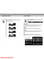
DVD Digital
AMP System
SPS-210
Downloaded From Disc-Player.com Samsung Manuals
Safety Precautions
Safety Instructions
The following illustrations represent precautions.
CAUTION
RISK OF ELECTRIC
SHOCK DO NOT OPEN
CAUTION. TO REDUCE THE RISK OF
ELECTRIC SHOCK, DO NOT REMOVE REAR
COVER. NO USER SERVICEABLE PARTS
INSIDE. REFER TO QUALIFIED SERVICE
PERSONNEL.
IMPORTANT NOTE
The mains lead on this equipment is supplied with a
moulded plug incorporating a fuse. The value of the fuse
is indicated on the pin face of the plug. If it requires
replacing, a fuse approved to BS1362 of the same rating
must be used.
Never use the plug with the fuse cover omitted if the
cover is detachable. If a replacement fuse cover is
required, it must be of the same colour as the pin face of
the plug. Replacement covers are available from your
dealer.
If the fitted plug is not suitable for the power points in
your house or the cable is not long enough to reach a
power point, you should obtain a suitable safety approved
extension lead or consult your dealer for asssistance.
However, if there is no alternative to cutting off the plug,
remove the fuse and then safely dispose of the plug. Do
not connect the plug to a mains socket, as there is a risk
of shock hazard from the bared flexible cord.
IMPORTANT
The wires in the mains lead are coloured in accordance
with the following code: BLUE = NEUTRAL
DANGER
This symbol is intended to alert you to the presence of
dangerous voltage within the product.
CAUTION
This symbol is intended to alert you to the presence of
important instructions accompanying the product.
The lightning flash with an arrowhead symbol,
within an equilateral triangle, is intended to alert
the user to the presence of uninsulated
“dangerous voltage” within the unit’s enclosure
that may be of sufficient magnitude to constitute
a risk of electric shock to persons.
The exclamation point within an equilateral
triangle is intended to alert the user to presence
of important operating and maintenance
(servicing) instructions in the literature
accompanying the appliance.
The wire coloured BLUE must be connected to the
terminal marked with the letter N or coloured BLUE or
BLACK. The wire coloured BROWN must be connected
to the terminal marked with the letter L or coloured
BROWN or RED.
WARNING : DO NOT CONNECT EITHER WIRE TO THE
EARTH TERMINAL WHICH IS MARKED WITH THE
LETTER E OR BY THE EARTH SYMBOL
, OR
COLOURED GREEN OR GREEN AND YELLOW.
Do NOT expose the DVD-VCR to
extreme temperature conditions
(below 5°C and above 40°C) or to
extreme humidity conditions (less
than 10% and more than 75%).
Do NOT expose the DVD-VCR to
direct sunlight.
Do NOT expose the DVD-VCR to
any liquids.
Do NOT place any objects on the
DVD-VCR or remote control
During a storm and/or lightning,
unplug the DVD-VCR from the mains
socket and aerial.
If the remote control is not used for a
long period of time, remove the
batteries and store it in a cool, dry
place.
Warning
To prevent fire or shock hazard, do not expose units
not specifically designed for outdoor use to rain or
moisture.
BROWN = LIVE
As these colours may not correspond with the coloured
markings identifying the terminals in your plug, proceed
as follows: -
The lightning bolt is a warning sign alerting you to dangerous voltage inside the product.
DO NOT OPEN THE DVD-VCR. Refer to service personnel.
Attention : Installation should be performed by
qualified service personnel only in accordance
with the National Electrical Code or applicable
local codes.
Power Disconnect. Units with or without ONOFF switches have power supplied to the unit
whenever the power cord is inserted into the
power source; however, the unit is operational
only when the ON-OFF switch is in the On
position. The power cord is the main power
disconnect for all units.
1
Downloaded From Disc-Player.com Samsung Manuals
THIS DEVICE IS NOT FOR USE IN INDUSTRIAL
ENVIRONMENTS
2
CONTENTS
Cautions on Installation
• Do not dissemble the unit. Touching the inside of the unit will expose you to a risk of
electric shock.
Table of Contents
Safety Instructions ..........................................................................................................................................................2
Accessories ....................................................................................................................................................................3
Cautions on Installation ..................................................................................................................................................4
Features..........................................................................................................................................................................4
Part Names.................................................................................................................................................................5~7
Remote Control Names ..................................................................................................................................................8
System Connections.......................................................................................................................................................9
Connection to External Components............................................................................................................................10
Basic Operations...........................................................................................................................................................11
Speaker Setup..............................................................................................................................................................12
Component Selection ...................................................................................................................................................13
Mode Selection.............................................................................................................................................................14
Notes on Dolby Digital, DTS and MPEG......................................................................................................................15
• Be sure to disconnect the power plug from the AC outlet when installing the unit or before
dissembling the unit.
• When pulling out the power cord from the wall outlet, do not hold the cord because the
cord may be damaged to cause short-circuiting or cut.
• Do not touch the unit with wet hands to avoid a risk of electric shock.
• Be careful to avoid dropping foreign objects such as pins, hair or coins into the unit to
avoid a risk of electric shock or fire.
• When cleaning the unit, do not use gasoline or thinner. Use clean dry clothes.
• Do not cover the air vents with a newspaper, a tablecloth, a curtain, etc. in order not be
obstruct heat radiation.
Installation of Speaker System.....................................................................................................................................16
Troubleshooting ............................................................................................................................................................17
Specifications................................................................................................................................................................18
Warranty Card ..............................................................................................................................................................19
• Do not place the exposed fire source such as a burning candle on the unit.
• Failure to pay due attention to installation of the speakers may cause the clothes of the
net frame to be torn or broken.
• This unit is manufactured under license
from Dolby Laboratories Licensing
Corporation. Dolby and
symbol are
trademarks of Dolby Laboratories
Licensing Corporation.
Accessories
After unpacking, check that the following items are contained.
• “DTS” and “DTS Digital Surround” are the
registered trademarks of Digital Theater
Systems, Inc.
Features
Three (3) speaker cords for
front/center speakers (5 meters each)
One (1) set of nonskid
speaker pads
Two (2) speaker cords for surround
speakers (10 meters each)
One (1) instruction
manual
3
Downloaded From Disc-Player.com Samsung Manuals
One (1) optical cord
• Dolby Digital function
• DTS function
• Dolby Pro Logic function
• MPEG Multichannel function
• Various sound field modes of Theater, Hall and Stadium
• Digital signal input function (Optical/Coaxial)
• Analog signal input function (AUX 1/AUX 2)
• Built-in subwoofer
• High quality audio
• Dimmer function
One (1) RCA cord
4
Part Names
Part Names
Display panel
Front Panel Controls
1 Dolby Digital display
It is displayed when the DVD recorded in Dolby Digital is played.
1 MUTE button
Press this button to turn off the sound instantly.
2 INPUT display
It shows the input selection of the external components connected to the main unit.
2 TEST TONE button (see page 13)
Use this button to check the connection status of each speaker.
3 ST-BY ON button
Press this button to light the display lamp and to start the unit.
4 STANDBY display lamp
It displays the standby status when lit. Press the POWER button to turn the lamp off.
5 Remote Sensor
It receives the remote control signals for operation with the remote control unit.
6 Master Volume dial
It is used to adjust the volumes of all six channels at the same time and to adjust
the volume of each channel individually.
7 CH. LEVEL button (see page 13)
Use this button to adjust the volume of each channel separately.
8 MODE button (see page 15)
Use this button to select the sound mode.
9 INPUT SEL. Button (see page 14)
Press this button to select the desired one among the external components
connected to the main unit.
5
Downloaded From Disc-Player.com Samsung Manuals
3 DTS display
It is displayed when the DVD recorded in DTS is played.
4 OPTICAL display
It shows that OPTICAL is selected for the digital input signal.
5 MPEG display
It is displayed when the DVD recorded in MPEG Multichannel is played.
6 COAXIAL display
It shows that COAXIAL is selected for the digital input signal.
7 TEST TONE display
It is displayed when the speaker volumes of six channels are adjusted.
8 ANALOG display
It shows that ANALOG is selected for the digital input signal.
9 LEVEL display
It is displayed when the speaker volume of each channel is adjusted.
10 Speaker display
It indicates the speakers in operation.
11 dB display
It is displayed with numerals when the volume of each channel or the entire volume is adjusted.
12 Operation display
It displays the functions in the current operational mode.
6
Part Names
Remote Control Names
12
1
11
DVD
SELECT
CENTER
2
3
AMP
10
9
WOOFER
SURROUND
4
5
6
7
30
INPUT
30
8
TONE
7~10m
DVD
DIMMER
MODE
MUTE
AMP
VOL.
AMP
SELECT
CENTER
WOOFER
SURROUND
INPUT
DIMMER
MODE
TONE
AMP
VOL.
MUTE
TV VOL.
TV CH.
TV MUTE
SET-UP
Reception Angle of
Remote Control Unit
1 DVD/AMP POWER button
Press the button to turn on the power to the unit.
Rear
1 Power switch
It turns the main power source on and off.
2 Digital signal input jacks (OPTICAL/COAXIAL)
For connection with an external component having the optical or coaxial output jack.
3 Analog signal input jacks (AUX1/AUX2)
For connection with up to two external components having the analog output jack.
4 Speaker output jacks
For connection with front L/R speakers, center speaker, and surround L/R spearkers.
5 Power cord
2 DVD button
Use this button to select the DVD function.
3 Subwoofer volume control buttons
Use these buttons to adjust the volume of the subwoofer.
The remote control works within the range
of 30 degrees to both sides and within the
distance of 7-10 meters from the remote
sensor of the unit.
4 TONE button (TEST TONE)
Use this button to check the connection status of each speaker.
5 INPUT button
Press this button to select the desired one among the external components connected to the unit.
6 MUTE button
Press this button to turn off the audio temporarily during playback of music or movie.
7 MODE/DIMMER button
MODE : For selection of sound field modes
DIMMER : For adjustment of brightness of the displays
8 AMP volume control buttons
Use these buttons to adjust the volume of all speakers at the same time.
9 Surround speakers volume control buttons
Use these buttons to adjust the volume of both surround speakers at the same time.
10 AMP button
Press this button for selection of AMP functions.
11 TV POWER button
Press this button to turn on the TV.
12 Center speaker volume control buttons
Use these buttons to adjust the volume of the center speaker.
7
Downloaded From Disc-Player.com Samsung Manuals
8
System Connections
Connection to External Components
Be sure to turn off the power before connecting the external component to the unit.
Connecting the Speakers
To protect the speakers, make connections while the power to the unit is turned off.
Surround R speaker
Surround L speaker
Blue
Digital External Component
Black
Connect with the external
components using digital signals.
Ex) CD recorder, MD, DVD, etc.
Front L speaker
Front R speaker
Center speaker
Blue
White
Green
RED
STANDBY/ON
PHONES
INPUT
Gray
LEVEL
OPEN/CLOSE
DVD VCR
COPY
SELECT
PROG
REC
EJECT
Analog External Component
Connect with the external
components using analog signals.
Ex) VCR, TV, etc.
Note
• Connect the speaker cord plugs to the speaker jacks of the same color.
9
Downloaded From Disc-Player.com Samsung Manuals
10
Basic Operations
Speaker Setup
For convenience of checking the connection of each speaker and volume adjustment, this unit
contains the TEST TONE function and the CH. LEVEL function.
How to adjust the volume with TEST TONE
1. Press the POWER button to turn on the power.
• When the power cord is plugged to the AC outlet, the ST-BY display is lit.
• When the power is turned on, the ST-BY display is turned off.
Note
The ST-BY display can be on when the “POWER” switch on
the rear panel of the unit is set to ON.
It is used at the initial setting after the system installation for adjustment of the
volume of each speaker so that the volume from each speaker can be heard at the
same level from the listening position depending on the layout of the room.
1. Press the TEST TONE button.
• The display for selection switches in the following order at the interval of two
seconds.
2. Use the INPUT SEL. Button to select the component.
•
2. Select the desired channel and use the MASTER VOLUME to
adjust the volume between –10dB and +10dB.
3. Operate the selected component.
• Refer to the instruction manual of each component for detailed information of
operation.
4. Adjust the volume.
• The volume may be adjusted between 1 (MIN) and 50 (MAX).
3. The channel switches to the next channel in three seconds after
adjusting the volume of the selected channel.
4. After adjusting the volume of all channels, press the TEST TONE
button again.
How to adjust the volume with CH. LEVEL
DIMMER function
When watching a movie in the dark, this function is useful to prevent
distraction due to the display of the main unit. The brightness of the
display can be selected among Bright Dim Off.
1. Automatic DIMMER function: After the ST-BY power is turned on,
the display is dimmed automatically in 15 seconds.
2. Manual DIMMER function: Press and hold down the “MODE” button
on the main unit or the remote control unit for 1.5 seconds
repeatedly to select among the choices of brightness of the display.
Note
* Press the MUTE button to turn off the sound instantly.
• The ST-BY display on the main unit blinks.
• It is convenient when you have a guest or answer the phone.
• To turn on the sound back, press the MUTE button again.
11
Downloaded From Disc-Player.com Samsung Manuals
It is usually used during playback. Adjust the volume to the listener’s taste depending
on the situation at the time of watching the movie or enjoying the music.
1. Press the CH. LEVEL button.
• The display for selection switches in the following order each time the button is
pressed.
* If the mode is set to “STEREO”:
2. Select the desired channel and use the MASTER VOLUME to
adjust the volume.
3. After adjusting the volume of all channels, it is switched to the
sound field mode in three seconds.
12
Component Selection
Mode Selection
Press the MODE button.
Press the INPUT SEL. button.
• The mode switches in the following order each time the button is pressed.
• The display shows the components for selection in the following order each time
the button is pressed.
DOLBY PRO LOGIC
Dolby Pro Logic is the stereo sound effect technology developed by Dolby Laboratories. With the sound
direction emphasis circuit, it provides the experience of sound movement between front and rear and
between left and right as in the theater system. The sound direction emphasis circuit separates the signals of
four channels (front L/R, center, rear) to enhance to three-dimensional sound depth.
THEATER
It is the surround function of providing the effect of being immersed in the 3D sound field and the feeling of
expansion as in the theater by reproducing the reflected sound and the reverberation in harmony.
STADIUM
It is the surround function of reproducing the unique tone that can be experienced only in the stadium, such
as the reverberation and the sound delay between the stadium and the listener’s ear. Select this mode to feel
the effect that the listener is in the stadium when watching the sports broadcasting or outdoor concert
programs.
HALL
It is the surround function of reproducing the sound effect in the concert hall by realizing the spatial
resonance and the reflected sound from different directions of the ceiling and the walls in the concert hall.
Select this mode for enjoying the concert, opera or orchestra to feel the effect that the listener is in the
concert hall.
Surround Effect by Audio Programs
Program
Speaker Configuration According to
the Surround Type
Type
DTS
Dolby Digital
MPEG
Dolby Pro Logic
Stereo
Theater
Hall
13
Downloaded From Disc-Player.com Samsung Manuals
Front
L/R
Sub
Cen Surround
woofer
L/R
ter
DTS Dolby Digital MPEG Dolby Pro Logic
Stereo
Theater Hall
Program marked
with DTS
Program marked
with Dolby Digital
Program marked
with MPEG
Program marked
with Dolby Pro Logic
Music
Concert
Sports
Old Movie
Program with
monaural sound
Educational and
news program
14
Notes on Dolby Digital, DTS and MPEG
DOLBY DIGITAL 5.1CH
Dolby Digital is the three-dimensional sound effect technology through digital signal processing of the next
generation, developed by Dolby Laboratories, and provides the sound completely split by six channels.
Six channels in Dolby Digital are called as 5.1-channel, of which 5 means the front L/R, center and rear L/R
channels. These five channels provide all audible frequency range of 20 – 20,000 Hz. Meanwhile, 0.1 channel
means the subwoofer, providing the bass range below 120 Hz.
Digital symbol is marked on the DVD.
Installation of Speaker System
To achieve the optimum quality of the sound effect provided by this unit, it is very
important to position the speakers properly. Refer to the following description for a better
sound experience.
Standard Speaker Positions
• Front L/R Speakers: Install the speakers on the left and right side in front of the listener at the
height of the listener’s ears and arrange the speakers to aim at the listening
position.
• Center Speaker: Install the speaker at the front center at the height of the listener’s ears.
DTS 5.1CH
DTS is the technology developed by Digital Theater Systems, Inc. Like Dolby Digital, it also provides the sixchannel mode consisting of front L/R, center, rear L/R and subwoofer and the same frequency range.
The difference between DTS and Dolby Digital lies in the data compression. Dolby Digital has a higher compression
ratio than DTS, thus occupying less space in the storage media. On the other hand, DTS occupies larger space
with a lower compression ratio but has gained a reputation that more emphasis is placed on the sound quality.
symbol is marked on the DVD.
• Surround L/R Speakers: Install the speakers on the left and right side in the rear of the listener at
the height of the listener’s ears and arrange the speakers to aim at the
listening position.
• If the speakers cannot be positioned at the height of the listener’s ears because of the structure of
the room, install the speaker above the listener’s ears. Make sure that the speakers are placed to
aim at the listening position.
• Subwoofer: Install the speaker on the floor in front of the listener.
* Install the subwoofer on hard floor keeping a distance of at least 10cm to the wall.
* Since there is a speaker on the left of the main unit, make sure that the left side is clear of any
obstruction.
MPEG 5.1CH
MPEG is a method of compression techniques for reproducing high quality of video and audio signals for
digital TV or DVD. Like Dolby Digital and DTS, it provides the six-channel mode consisting of front L/R,
center, rear L/R and subwoofer and the same frequency range.
MPEG )l( Multichannel symbol is marked on the DVD.
Center
Speaker
Front L
Speaker
Main
NOTE
Front R
Speaker
When installing the subwoofer, keep a
distance of at least 10cm to the wall
and at least 30cm to the TV.
DOLBY DIGITAL 2CH/DTS 2CH/MPEG 2CH
It is the function of integrating six channels into two channels for output so that the digital strips encoded in
six channels can be made compatible with the conventional 2-channel stereo system.
As this unit basically supports six channels, it may not be necessary to convert the input signals for 2-channel
system, but if the DVD to be played is encoded in 2 channels, it is played in 2CH mode.
Surround L
Speaker
15
Downloaded From Disc-Player.com Samsung Manuals
Surround R
Speaker
16
Ω∫««ƒø Ω∫≈ƒµÂ º≥ƒ°
Specifications
Troubleshooting
Problem
No power
No sound from the
speaker
Check Point
1. The power cord is not plugged
in the AC outlet.
2. The “POWER” switch on the
rear panel of the main unit is
not set to ON.
1. Plug the power cord tightly.
1. The speaker cords are not
connected to the speaker
terminals of the main unit or to
the speaker itself.
2. DVD, LDP, TV, etc. is not
connected to the INPUT terminal.
3. Optical cord is stained with dirty
objects.
4. MASTER VOLUME is set to the
minimum.
5. Muting is activated.
1. Check the connection of the
speaker cords.
1. MASTER VOLUME is set too
high.
Sound distortion
Remote control not
working
5.1CH not
displayed, and only
2CH or STEREO is
played
Remedies
2. The volume of the subwoofer is
set too high.
1. The distance to the main unit is
too far.
2. The batteries ran out.
3. The remote sensor is exposed
to direct sunlight.
1. The DVD player is not set to
5.1CH. (Refer to the instruction
manual of the DVD player.)
2. The DVD is encoded for 2channel system.
17
Downloaded From Disc-Player.com Samsung Manuals
2. Set the “POWER” switch to
ON.
Main Amplifier
• Output (at all channels driven)
Front L/R
Center
Surround L/R
Subwoofer
RMS
Total 175 Watts
25+25W
MAX.
Total 350 Watts
50+50W
25W
50W
25+25W
50+50W
50W
100W
• Analog input sensitivity/impedance .................................................................. 900mV / 47K Ohm
• Power......................................................................................................................... 230V / 50Hz
• Dimensions ............................................................................................ W252XD423XH266(mm)
2. Connect to the INPUT
terminal.
3. Wipe the cord with a soft
cloth.
4. Adjust the MASTER VOLUME.
5. Press the MUTE button
again.
Digital Specifications
• Input sensitivity/resistance .................................................................................. 32, 44.1, 48KHz
• Digital input impedance ........................................................................ COAXIAL 0.5V / 75 Ohm
Speakers
* Front L/R and Surround L/R
1. Lower the MASTER
VOLUME.
2. Lower the volume of the
subwoofer.
- Speaker........................................................................................... 3 inch + PEI Dome Speaker
- Impedance .............................................................................................................................. 4Ω
- Frequency range .................................................................................................. 100Hz~20KHz
- Dimensions .......................................................................................... W100XD103XH100(mm)
* Center Speaker
1. Use the remote control unit
at a closer distance.
2. Replace the batteries.
3. Block the direct sunlight.
- Speaker ..................................................................................................................... Dual 3 inch
- Impedance .............................................................................................................................. 4Ω
- Frequency range ................................................................................................. 100Hz~20KHz
- Dimensions .......................................................................................... W247XD103XH100(mm)
* Subwoofer
- Speaker ............................................................................................... 8 inch Magnetic Shielded
- Impedance .............................................................................................................................. 8Ω
- Frequency range .................................................................................................... 50Hz~200Hz
18
UNITED KINGDOM
This Samsung product is warranted for the period of twelve (12) months
from the original date of purchase, against defective materials and
workmanship. In the event that warranty service is required, you should
return the product to the retailer from whom it was purchased.
However, Samsung Authorised Dealers and Authorised Service Centres in
other EC Countries will comply with the warranty on the terms issued to
purchasers in the country concerned. In case of difficulty, details of our
Authorised Service Centres are available from:
Samsung Electronics (U.K.) Ltd.,
Euro Service Centre, Stafford Park 12,
TELFORD, Shropshire TF3 3BJ,
Tel: 0870) 2420303, Fax: 01952) 207117
■ WARRANTY CONDITIONS
1. The warranty is only valid if, when warranty service is required, the
warranty card is fully and properly completed and is presented with the
original invoice or sales slip or confirmation, and the serial number on
the product has not been defaced.
2. Samsung’s obligations are limited to the repair or, at its discretion,
replacement of the product or the defective part.
3. Warranty repairs must be carried out by Authorised Samsung Dealers or
Authorised Service Centres. No re-imbursement will be made for repairs
carried out by non Samsung Dealers and, any such repair work and
damage to the products caused by such repair work will not be covered
by this warranty.
REPUBLIC OF
IRELAND
5. This warranty covers none of the following:
a) Periodic check ups, maintenance and repair or replacement of parts
due to normal wear and tear.
b) Cost relating to transport, removal or installation of the product.
c) Misuse, including the faiure to use this product for its normal
purposes or incorrect installation.
d) Damage caused by Lightning, Water, Fire, Acts of God, War, Public
Disturbances, incorrect mains voltage, improper ventilation or any
other cause beyond the control of Samsung.
6. This warranty is valid for any person who legally acquired possession
of the product during the warranty period.
7. The consumers statutory rights in any applicable national legislation
whether against the retailer arising from the purchase contract or
otherwise are not affected by this warranty. Unless there is national
legislation to the contrary, the rights under this warranty are the
consumers sole rights and Samsung, its subsidiaries and distributors
shall not be liable for indirect or consequential loss or any damage to
records, compact discs, videos or audio taper or any other related
equipment or material.
SAMSUNG ELECTRONICS (U.K.) LTD.
4. This product is not considered to be defective in materials nor
workmanship by reason that it requires adaptation in order to conform to
national or local technical or safety standards in force in any Country
other than the one for which the product was originally designed and
manufactured. This warranty will not cover, and no re-imbursement will
be made for such adaptation nor any damage which may result.
19
Downloaded From Disc-Player.com Samsung Manuals
20