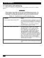
1
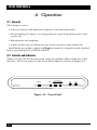
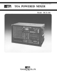
MARCH 1997
MX895A
MX895AE
Local Fiber Mux-6
-6
l Mux
Loca
LLB
SYNC
AL
LOC
RLB
LOSS
OTE
REM
TEST
ER
POW
CUSTOMER
SUPPORT
INFORMATION
Order toll-free in the U.S.: Call 877-877-BBOX (outside U.S. call 724-746-5500)
FREE technical support 24 hours a day, 7 days a week: Call 724-746-5500 or fax 724-746-0746
Mailing address: Black Box Corporation, 1000 Park Drive, Lawrence, PA 15055-1018
Web site: www.blackbox.com • E-mail: [email protected]
LOCAL FIBER MUX-6
FEDERAL COMMUNICATIONS COMMISSION
AND
INDUSTRY CANADA
RADIO FREQUENCY INTERFERENCE STATEMENTS
This equipment generates, uses, and can radiate radio-frequency energy, and if not
installed and used properly, that is, in strict accordance with the manufacturer’s
instructions, may cause interference to radio communication. It has been tested
and found to comply with the limits for a Class A computing device in accordance
with the specifications in Subpart B of Part 15 of FCC rules, which are designed to
provide reasonable protection against such interference when the equipment is
operated in a commercial environment. Operation of this equipment in a
residential area is likely to cause interference, in which case the user at his own
expense will be required to take whatever measures may be necessary to correct
the interference.
Changes or modifications not expressly approved by the party responsible
for compliance could void the user’s authority to operate the equipment.
This digital apparatus does not exceed the Class A limits for radio noise emission from
digital apparatus set out in the Radio Interference Regulation of Industry Canada.
Le présent appareil numérique n’émet pas de bruits radioélectriques dépassant les limites
applicables aux appareils numériques de la classe A prescrites dans le Règlement sur le
brouillage radioélectrique publié par Industrie Canada.
1
LOCAL FIBER MUX-6
NORMAS OFICIALES MEXICANAS (NOM)
ELECTRICAL SAFETY STATEMENT
INSTRUCCIONES DE SEGURIDAD
1. Todas las instrucciones de seguridad y operación deberán ser leídas antes de
que el aparato eléctrico sea operado.
2. Las instrucciones de seguridad y operación deberán ser guardadas para
referencia futura.
3. Todas las advertencias en el aparato eléctrico y en sus instrucciones de
operación deben ser respetadas.
4. Todas las instrucciones de operación y uso deben ser seguidas.
5. El aparato eléctrico no deberá ser usado cerca del agua—por ejemplo, cerca
de la tina de baño, lavabo, sótano mojado o cerca de una alberca, etc..
6. El aparato eléctrico debe ser usado únicamente con carritos o pedestales que
sean recomendados por el fabricante.
7. El aparato eléctrico debe ser montado a la pared o al techo sólo como sea
recomendado por el fabricante.
8. Servicio—El usuario no debe intentar dar servicio al equipo eléctrico más allá
a lo descrito en las instrucciones de operación. Todo otro servicio deberá ser
referido a personal de servicio calificado.
9. El aparato eléctrico debe ser situado de tal manera que su posición no
interfiera su uso. La colocación del aparato eléctrico sobre una cama, sofá,
alfombra o superficie similar puede bloquea la ventilación, no se debe colocar
en libreros o gabinetes que impidan el flujo de aire por los orificios de
ventilación.
10. El equipo eléctrico deber ser situado fuera del alcance de fuentes de calor
como radiadores, registros de calor, estufas u otros aparatos (incluyendo
amplificadores) que producen calor.
11. El aparato eléctrico deberá ser connectado a una fuente de poder sólo del
tipo descrito en el instructivo de operación, o como se indique en el aparato.
2
LOCAL FIBER MUX-6
12. Precaución debe ser tomada de tal manera que la tierra fisica y la polarización
del equipo no sea eliminada.
13. Los cables de la fuente de poder deben ser guiados de tal manera que no
sean pisados ni pellizcados por objetos colocados sobre o contra ellos,
poniendo particular atención a los contactos y receptáculos donde salen del
aparato.
14. El equipo eléctrico debe ser limpiado únicamente de acuerdo a las
recomendaciones del fabricante.
15. En caso de existir, una antena externa deberá ser localizada lejos de las lineas
de energia.
16. El cable de corriente deberá ser desconectado del cuando el equipo no sea
usado por un largo periodo de tiempo.
17. Cuidado debe ser tomado de tal manera que objectos liquidos no sean
derramados sobre la cubierta u orificios de ventilación.
18. Servicio por personal calificado deberá ser provisto cuando:
A: El cable de poder o el contacto ha sido dañado; u
B: Objectos han caído o líquido ha sido derramado dentro del aparato; o
C: El aparato ha sido expuesto a la lluvia; o
D: El aparato parece no operar normalmente o muestra un cambio en su
desempeño; o
E: El aparato ha sido tirado o su cubierta ha sido dañada.
3
LOCAL FIBER MUX-6
TRADEMARKS USED IN THIS MANUAL
Any trademarks mentioned in this manual are acknowledged to be the property of the
trademark owners.
4
LOCAL FIBER MUX-6
Contents
Chapter
Page
1. Specifications . . . . . . . . . . . . . . . . . . . . . . . . . . . . . . . . . . . . . . . . . . . . . . .6
1.1 Sub-Channels . . . . . . . . . . . . . . . . . . . . . . . . . . . . . . . . . . . . . . . . . . . .6
1.2 Main Channel . . . . . . . . . . . . . . . . . . . . . . . . . . . . . . . . . . . . . . . . . . .6
1.3 General . . . . . . . . . . . . . . . . . . . . . . . . . . . . . . . . . . . . . . . . . . . . . . . .7
2. Introduction . . . . . . . . . . . . . . . . . . . . . . . . . . . . . . . . . . . . . . . . . . . . . . . .9
2.1 General . . . . . . . . . . . . . . . . . . . . . . . . . . . . . . . . . . . . . . . . . . . . . . . .9
2.2 Functional Description . . . . . . . . . . . . . . . . . . . . . . . . . . . . . . . . . . . .9
2.3 Applications . . . . . . . . . . . . . . . . . . . . . . . . . . . . . . . . . . . . . . . . . . . . .10
3. Installation . . . . . . . . . . . . . . . . . . . . . . . . . . . . . . . . . . . . . . . . . . . . . . . . .13
3.1 Site Preparation . . . . . . . . . . . . . . . . . . . . . . . . . . . . . . . . . . . . . . . . . .13
3.2 Setup . . . . . . . . . . . . . . . . . . . . . . . . . . . . . . . . . . . . . . . . . . . . . . . . . .13
3.3 Installation in 19” Racks . . . . . . . . . . . . . . . . . . . . . . . . . . . . . . . . . . .14
3.3.1 General . . . . . . . . . . . . . . . . . . . . . . . . . . . . . . . . . . . . . . . . . . .14
3.3.2 Installation of Unit . . . . . . . . . . . . . . . . . . . . . . . . . . . . . . . . . .14
3.4 Electrical Installation . . . . . . . . . . . . . . . . . . . . . . . . . . . . . . . . . . . . . .15
3.4.1 AC Power . . . . . . . . . . . . . . . . . . . . . . . . . . . . . . . . . . . . . . . . . .15
3.4.2 Sub-Channels . . . . . . . . . . . . . . . . . . . . . . . . . . . . . . . . . . . . . . .16
3.4.3 Main Channel . . . . . . . . . . . . . . . . . . . . . . . . . . . . . . . . . . . . . .16
4. Operation . . . . . . . . . . . . . . . . . . . . . . . . . . . . . . . . . . . . . . . . . . . . . . . . . .20
4.1 General . . . . . . . . . . . . . . . . . . . . . . . . . . . . . . . . . . . . . . . . . . . . . . . .20
4.2 Controls and Indicators . . . . . . . . . . . . . . . . . . . . . . . . . . . . . . . . . . .20
4.3 Operating Procedure . . . . . . . . . . . . . . . . . . . . . . . . . . . . . . . . . . . . .22
4.4 System Tests . . . . . . . . . . . . . . . . . . . . . . . . . . . . . . . . . . . . . . . . . . . . .23
4.5 Fault Isolation and Troubleshooting . . . . . . . . . . . . . . . . . . . . . . . . .24
5
LOCAL FIBER MUX-6
1. Specifications
1.1 Sub-Channels
Transmission Format—Asynchronous
Data Rate—Up to 38.4 kbps (refer to Table 2-1 and 2-3)
Distortion—Refer to Table 1-1
Interface—EIA RS-232C/CCITT V.24
Connectors—(6) DB25 female
Number of Sub-channels—Up to 12 by attaching a channel doubler to each
of the connectors
Mode of Operation—Full duplex
1.2 Main Channel
Optical Interface (Dual Fiber)
Transmission Line—Double optical cable
Operating Range—3.2 miles (5 km)
Data Rate—2.4576 Mbps
Operating Wavelength—850 nanometers (optional 1300 nm)
Optical Output Level— -24 dBm min into 50/125 fiber, -20 dBm min
into 62.5/125 fiber, -16 dBm min into 100/140 fiber
Receiver Sensitivity— -40 dBm
Dynamic Range—24 dB
Fiberoptic Interface—Standard SMA or ST connectors
6
LOCAL FIBER MUX-6
1.3 General
Diagnostics
Local Digital Loopback—Activated by pushbutton
Remote Digital Loopback—Activated by pushbutton
Switches/Indicators
Power Indicator (Green)—On when unit is powered
Test Indicator (Yellow)—On when local or remote unit is performing
a loopback
Local Sync Loss Indicator (Red)—On when synchronization is lost at
local unit
Remote Sync Loss Indicator (Red)—On when synchronization is lost at
remote unit
LLB Switch—When pressed, unit is performing local loopback
RLB Switch—When pressed, unit is performing remote loopback
Physical Description
Size—1.72"H (1 U) x 13.3"W x 8.6"D (4.4 x 33.8 x 22 cm)
Weight—3.5 lb. (1.6 kg)
7
LOCAL FIBER MUX-6
Environment
Temperature—32 to 122°F (0 to 50°C)
Humidity—Up to 90% non-condensing
Power
Power Requirements—110/115/230 VAC (±10%), 47–63 Hz, 7.5 VA max.
8
LOCAL FIBER MUX-6
2. Introduction
2.1 General
The Local Fiber Mux-6 is a full-duplex time-division asynchronous
multiplexor enabling up to twelve async terminals to be multiplexed onto a
single channel. The Local Fiber Mux-6 is intended for use in manufacturing
facilities, building complexes, campuses, and other similar point-to-point
applications.
2.2 Functional Description
The Local Fiber Mux-6 contains six sub-channels that can be expanded to
twelve through connection of channel doubler cables. The number of
channels available (6/12) is set by a user-selectable strap.
When the unit is set for six channels, each channel can be used to transmit
full-duplex data end-to-end. When the unit is set for twelve channels, each
sub-channel can be used for either data or control-signal transmission,
according to the specific application. For example: six channels can be used
to transmit full-duplex data and six can be used to transmit control signals
end-to-end, or else the full twelve channels can be used to transmit full-duplex
data end-to-end.
The main channel interface has a dual fiber for transmission over duplex
fiberoptic cable.
Multiplexing is implemented using an oversampling technique. Each of
the twelve channels is sampled at 157.2 kbps rate. Table 2-1 summarizes
Local Fiber Mux-6 performance with various options and modes of operation.
NOTE
Whenever possible (if the number of channels is less than or equal to 6)
we recommend that you operate the Local Fiber Mux-6 in the six-channel
mode, which results in less distortion.
9
LOCAL FIBER MUX-6
Table 2-1. Performance in Various Modes of Operation.
No. of Subchannels in use
Max.
Data Rate
Distortion (%)
Optical
6
19.2
6.25
6
38.4
12.5
12
19.2
12.5
12
38.4
25
2.3 Applications
The Local Fiber Mux-6 is used mainly for point-to-point configurations where
distances of up to several kilometers are involved. A typical application is
demonstrated in Figure 2-1 where a cluster of terminals is connected to a host
computer through a single link. Different configurations are available using
dual-fiber transmission media.
Table 2-2. Point-to-Point Configurations.
10
No. of Subchannels
Maximum data rate on each sub-channel (25% distortion)
12 data
38.4 kbps
6 data
38.4 kbps*
6 data and
6 control
38.4 kbps
LOCAL FIBER MUX-6
Local Fiber
Mux-6
Local Fiber
Mux-6
Async
Computer
Figure 2-1. Typical Point-to-Point Installation.
For installations involving clusters of terminals distributed in several
locations, Local Fiber Mux-6 units may be installed in a ring-type
configuration (refer to Figure 2-2). At each site the unconnected channels
must be bypassed by shorting Pins 2 and 3 of the relevant sub-channel
connector.
Table 2-3. Ring Configuration.
Data rate
on each
Sub-channel
Distortion
per Node (%)
Number of
Nodes/Sites
19.2 kbps
12.5
4
9.6 kbps
6.25
4
4.8 kbps
3.125
8
2.4 kbps
1.5625
16
1.2 kbps
0.78125
32
11
LOCAL FIBER MUX-6
4
TERM
1
T
2 WIRE
1
R
4
HOST
12
R
T
2 WIRE
2 WIRE
4
TERM
4
TERM
R
T
5
9
8
12
R
2 WIRE
T
Figure 2-2. Typical Ring Installation.
12
LOCAL FIBER MUX-6
3. Installation
3.1 Site Preparation
The Local Fiber Mux-6 is installed within 5 feet (1.5 m) of a grounded
AC outlet.
3.2 Setup
a) Unscrew the two upper-cover screws located at the back of the unit
(refer to Figure 3-3).
b) Slide the rear drawer out.
c) Locate the strap marked “select 6 or 12 channels” (indicated by an arrow
on the circuit board). For up to 6 channels with no control applications,
place the strap between the center pin, and the one marked “6.” For any
other applications, place the strap between the center pin and the one
marked “12” (refer to Figure 3-1).
d) Locate the strap marked GND. According to your requirements, set the
signal ground to be connected to shielding (chassis) ground or floating
(NC).
e) Replace the rear drawer.
f) Fasten the two upper cover screws at the back of the unit.
GND
NC
12
6
SELECT
6 OR 12
CHANNELS
Figure 3-1. Strapping Diagram.
13
LOCAL FIBER MUX-6
3.3 Installation in 19" Racks
3.3.1 GENERAL
The Local Fiber Mux-6 can be installed in a 19" rack. Its height is slightly less
than 1U (1.75"), and the width is slightly less than the available mounting
width.
WARNING
Disconnect the units from mains power while performing the following
procedures.
3.3.2 INSTALLATION OF A UNIT
The rack-adapter components for single-unit installation include two short
brackets. The brackets are fastened by means of screws to the side walls for
the case, as shown in Figure 3-2. The brackets are attached to the two side
walls of the unit.
a) To prepare the unit for rack installation, attach the two brackets to the
side walls of the unit. Each bracket is fastened by means of two screws
(with flatwashers), which are inserted into the two front holes on the
wide wall (nuts are already in place, on the inner side of the wall).
b) After attaching the brackets, the unit is ready for installation in the 19"
rack. Fasten the brackets to the side rails of the 19" rack by means of
four screws—two per side (not included in the kit).
14
LOCAL FIBER MUX-6
Figure 3-2. Installation of a Unit in a 19" Rack.
3.4 Electrical Installation
In the following discussions, refer to Figure 3-3 (rear panel).
3.4.1 AC POWER
AC power is supplied to the Local Fiber Mux-6 through a 5 foot (1.5 m) cord
terminated by a grounded 3-wire plug. The AC cord is fused at the rear panel
AC power receptacle of the unit. A slow-blow fuse of 0.1A is required for
230V operation, and a 0.2A fuse is required for 115V operation.
15
LOCAL FIBER MUX-6
3.4.2 SUB-CHANNELS
Six D-type 25-pin female connectors on the rear panel enable connection to
the unit. Detailed information about the signals present at these connectors
is given in Table 3-1. For twelve-channel operation, channel doublers are
required. Refer to Figure 3-4 for the pinout of the channel doubler. For sixchannel operation, with full duplex data and end-to-end control signals on
each channel, refer to Figure 3-5 (DTR to DSR control signal) or to Figure 3-6
(RTS to DCD control signal).
3.4.3 MAIN CHANNEL
Two SMA connectors are located on the rear panel, marked TX and RX.
Remove the protective caps from the connectors and keep them in a safe
place for later use. Clean both connectors to remove dust accumulated
during shipment (using ethanol or similar cleaning fluid). Connect the
transmit fiber to the TX connector and the receive fiber to the RX connector,
and secure the fastening nuts. At the remote unit, the transmit fiber must be
connected to RX and the receive fiber to TX.
WARNING
Do not overtighten the fiberoptic connectors.
Unscrew these screws
to pull out circuit board.
MAIN CHANNEL
FUSE
~115V/O.2AS.B.
RX
CH 1/7
CH 2/8
CH 3/9
CH 4/10
CH 5/11
CH 6/12
TX
Figure 3-3. Local Fiber Mux-6 Rear Panel.
16
LOCAL FIBER MUX-6
Table 3-1. Sub-Channel Connector Pin Assignment.
CCITT
V.24
EIA
RS-232C
Pin.
No.
Signal Name
Description
101
AA
1
Protective Ground
Chassis ground. May
be isolated from
signal ground.
102
AB
7
Signal Ground
Common signal and
DC power supply
ground.
103
BA
2 (14)*
Transmit Data
Serial digital data
from a terminal or
other source into the
Local Fiber Mux-6.
104
BB
3 (16)
Receive Data
Serial digital data
output from the Local
Fiber Mux-6.
105
CA
4 (19)
Request to Send
A positive level to the
Local Fiber Mux-6
when data transmission is desired.
106
CB
5 (13)
Clear to Send
A positive level from
the Local Fiber Mux-6
(if data transmission
is possible).
107
CC
6 (21)
Data Set Ready
A positive DC voltage
(+8V) from the Mux
indicating the unit is
powered.
109
CF
8 (12)
Receive Line Signal
Detector (Carrier
Detect)
A positive level from
the Mux except
when either a sync
loss occurs or remote
loopback is
performed.
—
—
9
10
+8 volts
-8 volts
These signals are
reserved for data-set
testing and for powering miniature
modems.
*Pin numbers in parentheses are for the secondary
channel available when using a channel-doubler cable.
17
LOCAL FIBER MUX-6
Local Fiber Mux-6
Sub-Channel
Connector
Channel Doubler
Protective Ground
Transmitted Data (TD)
Received Data (RD)
Request to Send (RTS)
Clear to Send (CTS)
Data Set Ready (DSR)
Received Line Signal Detector
Not used
1
2
3
4
5
6
8
15
17
20
24
7
1
2
3
4
5
6
8
15
17
20
24
7
Port A
1
2
3
4
5
6
8
15
17
20
24
7
Port B
Secondary TD
Secondary RD
Secondary RTS
Secondary CTS
Secondary DSR
Secondary RLSD
Not used
14
16
19
13
21
12
11
18
25
23
14
16
19
13
21
12
11
18
25
23
1
2
3
4
5
6
8
15
17
20
24
7
Figure 3-4. Connecting Channel Doubler to the Local Fiber Mux-6
Sub-Channel.
18
LOCAL FIBER MUX-6
Local Fiber Mux-6
Sub-Channel
Connector
Protective Ground
Transmitted Data (TD)
Received Data (RD)
Request to Send (RTS)
Clear to Send (CTS)
Data Set Ready (DSR)
Received Line Signal Detector
Signal Ground
Secondary TD
Secondary RD
1
2
3
4
5
6
8
7
14
16
Channel Doubler
1
2
3
4
5
6
8
7
14
16
Special
Cable 1
1
2
3
4
5
6
8
20
7
Figure 3-5. DTR to DSR End-to-End Control Signal.
Local Fiber Mux-6
Sub-Channel
Connector
Special
Cable 2
Channel Doubler
Protective Ground
Transmitted Data (TD)
Received Data (RD)
Request to Send (RTS)
Clear to Send (CTS)
Data Set Ready (DSR)
Received Line Signal Detector
Signal Ground
Secondary TD
Secondary RD
1
2
3
4
5
6
8
7
14
16
1
2
3
4
5
6
8
7
14
16
1
2
3
4
5
6
7
8
Figure 3-6. RTS to DCD End-to-End Control Signal.
19
LOCAL FIBER MUX-6
4. Operation
4.1 General
This chapter covers:
• A list of controls and indicators together with their functions.
• An operating procedure covering power-on, operating instructions, and
power-off.
• Information on strapping.
• A unit system test procedure for use by the operator and technician.
Installation procedures given in Chapter 3 must be completed and checked
before operating the Local Fiber Mux-6.
4.2 Controls and Indicators
Tables 4-1 and 4-2 list the functions of the Local Fiber Mux-6 indicators and
switches. The front panel of the Local Fiber Mux-6 is shown in Figure 4-1.
SYNC LOSS
POWER
RAD
TEST
LOCAL REMOTE
FLM-1
Figure 4-1. Front Panel.
20
LLB
RLB
LOCAL FIBER MUX-6
Table 4-1. Indicators.
Item
Indicator
Function
1
Power
Green LED lights when power is
present.
2
Test
Yellow LED lights when either local
or remote unit is performing a test.
3
Local Sync Loss
Red LED lights when synchronization
is lost at the local unit.
4
Remote Sync Loss
Red LED lights when synchronization
is lost at the remote unit.
Table 4-2. Indicators.
Item
Switch
Function
5
LLB
When pressed (pushed in) the unit
performs local loopback.
6
RLB
When pressed (pushed in) the unit
performs remote loopback.
21
LOCAL FIBER MUX-6
4.3 Operating Procedure
WARNING
When you plug in the Local Fiber Mux-6, the protective earth terminals of
this instrument must be connected to the protective conductor of the
(mains) power cord. The mains plug shall only be inserted in a socket
outlet provided with a protective earth contact. The protective action
must not be negated by use of an extension cord (power cable) without a
protective conductor (grounding). Make sure that only fuses with the
required rated current are used for replacement. The use of repaired
fuses and the short-circuiting of fuse holders must be avoided.
Whenever it is likely that the protection offered by fuses has been
impaired, the instrument must be made inoperative and secured against
any unintended operation.
Power-On
Apply AC power by connecting the AC power cord to an acceptable AC
source. If the power indicator lights, then the Local Fiber Mux-6 is powered.
If the local and remote Local Fiber Mux-6 units are in operation and properly
connected via the main channel, no other indicator should be ON. If
another condition exists, refer to Section 4.5 for troubleshooting information.
Operation
The Local Fiber Mux-6 operates entirely unattended except when performing
system tests.
Power-Off
To turn off Local Fiber Mux-6, simply remove the AC power cord from the AC
source.
Operational Field Strapping Changes
If you need to reconfigure the Local Fiber Mux-6 for twelve-channel mode or
six-channel mode, follow the appropriate set-up procedure described in
Section 3-2.
22
LOCAL FIBER MUX-6
4.4 System Tests
Two system tests are available in the Local Fiber Mux-6: local loopback and
remote loopback.
Local Loopback
When performing local loopback, the data from the local transmitter is
looped back to the local receiver at the digital level, thus checking all local
digital circuitry for proper operation. This test is activated by pressing the
LLB push-button located on the front panel. If the local unit is operating
properly, the yellow TEST indicator should light, and all other indicators
should be OFF. If the local and remote units are properly connected via the
main channel, the local transmitter analog interface and both the remote
analog and digital receiver sections are checked. The yellow TEST indicator
on the remote unit should also be lit if the units are properly connected.
Remote Loopback
Remote loopback loops back data from the remote receiver to the remote
transmitter, thus checking:
• All local digital circuitry
• Both local and remote analog interfaces
• Main channel link
• Remote digital receiver section.
This test is performed by pressing the RLB push-button on the front panel.
If both local and remote units operate properly, the yellow TEST indicators
should be lit at both units, and all other indicators should be OFF.
NOTE
When either local or remote loopback test is performed, the following
signals at the remote unit sub-channels are set to OFF (negative voltage)
condition:
• Received Data (Circuit 104)
• Clear to Send (Circuit 106)
• Receive Line Signal Detector (Circuit 109)
23
LOCAL FIBER MUX-6
4.5 Fault Isolation and Troubleshooting
Use Table 4-3 to help you troubleshoot any problems with the Local Fiber
Mux-6.
WARNING
These service instructions are for use by qualified personnel only. To
avoid electric shock, do not perform any servicing other than that
contained in the operating instructions unless you are qualified to do so.
Table 4-3. Fault Isolation and Troubleshooting.
Symptom
Action
All front panel indicators are OFF
(a) Check that power is supplied to the unit.
(b) Check the fuse inside the AC receptacle
on the rear panel and replace it with a new
one.
(c) Replace unit. The fault is probably in
the unit’s power-supply circuits.
Red LOCAL SYNC LOSS is ON
(a) Perform LLB. Yellow TEST indicator
should light and LOCAL SYNC LOSS
should go OFF. If not, replace the local
unit. Otherwise, proceed to step (b).
(b) Perform RLB. Yellow TEST indicator
should light and LOCAL SYNC LOSS
should go OFF. In that case, replace the
remote unit. Otherwise, proceed to step (c).
(c) Perform steps (a) and (b) at the remote
site. If the fault is still not located, replace
both units one at a time. If the problem
remains, the main-channel link is defective
and should be checked.
Red REMOTE SYNC LOSS is ON
Perform all the tests as in the case of
LOCAL SYNC LOSS, starting at the remote
site.
24
© Copyright 1997. Black Box Corporation. All rights reserved.
1000 Park Drive
•
Lawrence, PA 15055-1018
•
724-746-5500
•
Fax 724-746-0746