1
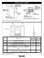
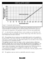
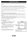
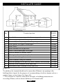
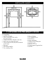
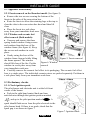
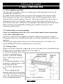
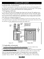
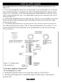
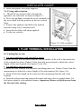
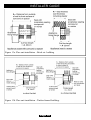
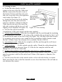
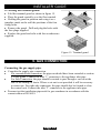
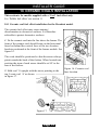
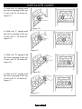
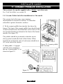
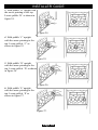
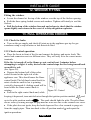
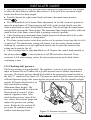
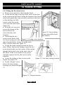
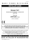
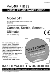
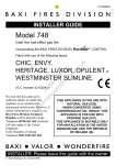
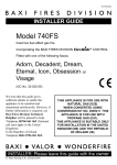
5115493/01
INSTALLER GUIDE
Model 541
fitted with
Decadent
Chic
or
fascia
ROOM SEALED RADIANT / CONVECTOR
GAS FIRE
(GC No. 32-032-65)
THIS APPLIANCE IS FOR USE WITH NATURAL GAS (G20).
THIS APPLIANCE IS SUITABLE ONLY FOR INSTALLATION IN THE UNITED
KINGDOM (GB) AND THE REPUBLIC OF IRELAND (IE).
We trust that this guide gives sufficient details to enable this appliance to be installed
and maintained satisfactorily. However, if further information is required, our
Baxi Fires Division Technical Helpline will be pleased to help.
Telephone 08706 061 065 (National call rates apply in the United Kingdom). In the
Republic of Ireland telephone 0044 8706 061 065.
INSTALLER: Please leave this guide with the owner
© Baxi Heating U.K. Ltd.
INSTALLER GUIDE
Safety First.
Baxi Fires Division fires are CE Approved and designed to meet the appropriate British
Standards and Safety Marks.
Quality and Excellence.
All Baxi Fires Division fires are manufactured to the highest standards of quality and
excellence and are manufactured under a BS EN ISO 9001 quality system accepted by
the British Standards Institute.
The Highest Standards
Baxi Fires Division is a member of the Society of British Gas Industries which works to
ensure high standards of safety, quality and performance.
Careful Installation
Baxi Fires Division is a CORGI registered company. All our gas fires must be
installed by a competent CORGI Registered Installer in accordance
with our Installer Guide and should not be fitted directly on to a
carpet or floor of combustible material.
Baxi Fires Division, Erdington, Birmingham B24 9QP
www.firesandstoves.co.uk
Because our policy is one of constant development and improvement, details may vary slightly from those
given in this publication
Page 2
INSTALLER GUIDE
CONTENTS
Section
Heading
Page
1. SAFETY
2. APPLIANCE DATA
3. LIST OF AVAILABLE KITS
4. GENERAL INSTALLATION REQUIREMENTS
5. UNPACKING AND PRELIMINARY CHECKS
6. GAS SUPPLY CONNECTION
7. WALL PREPARATION
7.1 Select appliance position.
7.2 Constructing a recessed opening.
7.3 Combustible wall materials.
7.4 Cutting the flue hole for brick, stone etc. building.
7.5 Cutting the flue hole in timber frame buildings.
7.6 Prepare appliance fixing holes.
8. FLUE TERMINAL INSTALLATION
8.1 Cutting flue to size.
8.2 Fitting to wall.
8.3 Fitting the terminal guard.
9. GAS CONNECTION
10. CERAMIC COALS INSTALLATION
11. CERAMIC PEBBLES INSTALLATION
12. WINDOW FITTING
13. FULL OPERATING CHECKS
14. FASCIA FITTING
14.1 Fitting the Decadent fascia
14.2 Fitting the Chic fascia
15. FINAL REVIEW
16. SERVICING & PARTS REPLACEMENT
16.1 To remove the fascia.
16.2 To remove window unit.
16.3 To remove the ceramic fuel effect and rear wall.
16.4 To remove the complete burner module.
16.5 To remove the burner from the burner module.
16.6 To remove the injector.
16.7 To remove the pilot unit.
16.8 To remove the gas valve.
16.9 To remove the switch and wiring loom.
Page 3
4
4
7
7
12
14
15
15
15
16
17
17
18
19
19
21
22
22
23
25
27
27
29
29
30
31
32
32
34
34
34
35
35
35
36
36
INSTALLER GUIDE
1. SAFETY
Installer
Before continuing any further with the installation of this appliance please read the
following guide to manual handling:
! The lifting weight of this appliance is as below
Model
Decadent
Chic
Heat Engine (kg)
12.58
12.58
Fascia / Firefront (kg) Combined Weight (kg)
4.75
17.33
3.65
16.23
! One person should be sufficient to lift the fire. If for any reason this weight is
considered too heavy then obtain assistance.
! When lifting always keep your back straight. Bend your legs and not your back.
! Avoid twisting at the waist. It is better to reposition your feet.
! Avoid upper body/top heavy bending. Do not lean forward or sideways whilst
handling the fire.
! Always grip with the palm of the hand. Do not use the tips of fingers for support.
! Always keep the fire as close to the body as possible. This will minimise the
cantilever action.
! Use gloves to provide additional grip.
! Always use assistance if required.
2. APPLIANCE DATA
This product uses a fuel effect, a burner compartment rear wall and gaskets
containing Refractory Ceramic Fibres (RCF), which are man-made vitreous
silicate fibres. Excessive exposure to these materials may cause irritation to eyes,
skin and respiratory tract. Consequently, it is important to take care when
handling these articles to ensure that the release of dust is kept to a minimum. To
ensure that the release of fibres from these RCF articles is kept to a minimum,
during installation and servicing we recommend that you use a HEPA filtered
vacuum to remove any dust and soot accumulated in and around the fire before
and after working on the fire. When replacing these articles we recommend that
the replaced items are not broken up, but are sealed within a heavy duty polythene
bag, clearly labelled as RCF waste. This is not classified as “hazardous waste” and
may be disposed of at a tipping site licensed for the disposal of industrial waste.
Protective clothing is not required when handling these articles, but we recommend
you follow the normal hygiene rules of not smoking, eating or drinking in the work
area and always wash your hands before eating or drinking. This appliance does
Page 4
INSTALLER GUIDE
not contain any component manufactured from asbestos or asbestos related
products.
Gas
Natural
Inlet pressure
20mbar
Input - Max. (Gross)
3.65kW (12,454 Btu/h)
Input - Min. (Gross)
1.5kW (5,118 Btu/h)
Inlet pressure (Cold)
20.0 ± 1.0mbar (8.0 ± 0.4in w.g.)
Gas connection
8mm pipe
Main burner
Simplex aerated
Burner injector
Bray Cat. 92 size 280
Pilot unit
Ignition
Aeration adjustment
Controls
Left side of firebox. Combined pilot jet, thermocouple sensor
and electrode. SIT ref. NGOP9706
Integral piezo on gas valve.
None required
Manual pilot and main burner off/on control (Right control).
Separate variable control (Left control) for main burner can be
operated by its control knob or from the high level rocker
switch. Fitted with flame supervision device and integral piezo
igniter
Batteries
4 x 1.5V AA
Walls
Minimum 102mm (4in.) thick.
Maximum 660mm (26in.) thick.
The appliance data label is located on a plate at the base of the fire. This can be seen by
removing the lower firefront / firefront casting.
This appliance must not be recessed into a combustible wall.
Page 5
INSTALLER GUIDE
Figure 1. Recess and flue hole dimensions
Key
Description
A
Model
Chic
Decadent
Appliance height (mm)
609
607
B
Appliance width (mm)
482
487
C
Appliance depth into room (mm)
104
133
Minimum mandatory clearance to combustible
D
surfaces projecting beyond the front of appliance
102
102
(mm).
Recommended clearance to non-combustible
E
51
51
surfaces for access purposes (mm).
Figure 2. Appliance dimensions and clearances (Fire dimensions are subject to
manufacturing deviation)
Page 6
INSTALLER GUIDE
3. LIST OF AVAILABLE KITS
Description
! Spacer kit (5 inch)
! Spacer kit (3 inch)
Part number
0595121
0595131
! Timber frame Flue Clearance kit.
This kit includes : -
0583141
1 off
1 off
1 off
1 off
Insulation for rear of fire
Flue clearance sleeve
Drip collar
External wall plate
Under no circumstances is the fire to be recessed into Timber frame constructions. For
timber framed installations see section 7.
4. GENERAL INSTALLATION REQUIREMENTS
4.1 The appliance can be installed into the following :a)
A minimum 4.5in rebate surround or 5in. spacer kit Part No 0595121. Where
either of these are mounted to a combustible wall make sure that there is no combustible
material or combustible cladding in the area indicated on the wall fixing template.
b)
A 2in rebate surround in conjunction with the 3in. spacer kit Part No 0595131.
Where the surround is mounted to a combustible wall make sure that there is no
combustible material or combustible cladding in the area indicated on the wall-fixing
template.
c)
Recessed into a builder’s opening or cavity of a non- combustible wall. The
minimum cavity size is shown in figure 1. A lintel may be required above the recess
opening. If in doubt seek expert building advice. Lintel construction details are given in
section 7 of this guide. This appliance must not be recessed into a combustible wall.
4.2 Note that soft wall coverings (e.g. embossed vinyl etc.) are easily affected by heat.
They may therefore, scorch or become discoloured when close to a heating appliance.
Please bear this in mind when installing.
4.3 Installation to a timber-framed building should be in accordance with the relevant
sections of The Institute of Gas Engineers publication IGE/UP/7 “Gas installations in
timber frame buildings”.
Please note that advice should be sought before installing in a timber frame building
since the alterations required may nullify any NHBC cover relating to the property. If in
doubt, guidance should be requested from your local authority planning or building
Page 7
INSTALLER GUIDE
department.
Under no circumstances is the fire to be recessed into Timber frame constructions.
For timber framed installations see section 7.
4.4 The installation must be in accordance with this guide.
For the user’s protection, in the United Kingdom it is the law that all gas appliances are
installed by competent persons in accordance with the current edition of the Gas Safety
(Installation and Use) Regulations. Failure to install the appliance correctly could lead
to prosecution. The Council for the Registration of Gas Installers (CORGI) requires its
members to work to recognised standards.
In the United Kingdom the installation must also be in accordance with:
All the relevant parts of local regulations.
The current edition of the Building Regulations issued by the Department of the
Environment and the Welsh Office, the Building Standards (Scotland) (Consolidation)
Regulations issued by the Scottish Development Department or the Building
Regulations (Northern Ireland) issued by the Department of the Environment for
Northern Ireland.
All relevant codes of practice.
The relevant parts of the current editions of the following British Standards:BS 5440 Part 1
BS 5871 Part 1
BS 6891
In the republic of Ireland the installation must also conform to:
a)
The relevant parts of the current edition of IS 813 “Domestic Gas Installations”
b)
All applicable national and local rules in force.
Where no specific instructions are given, reference should be made to the relevant
British Standard Code of Practice.
4.5 A minimum clearance of 51mm should be maintained at each side of the fire for
servicing access.
Any combustible side wall or other combustible projection must be at least 102mm
clear from direct exposure to the radiant surface of the appliance unless suitably
protected.
4.6 The minimum height from the base of the fire to the underside of any shelf made
from wood or other combustible materials is as follows:•
For a shelf up to 150mm deep
Minimum height = 780mm.
•
For a shelf deeper than 150mm
780mm + 12.5mm for every 25mm depth over 150mm.
(See graph 1)
Page 8
INSTALLER GUIDE
Graph 1. Combustible shelf clearances.
There is no restriction on the position or depth of non-combustible projections for all
normal installations. Installation into an unusually tightly restricted recess, however,
could cause the temperature of the appliance surfaces to become unacceptably high.
4.7 It is advisable that combustible fabrics such as curtains are not fitted above the
fire. If, however, this is unavoidable, the extreme bottom edge of the fabric must be at
least 780mm above the base of the fire.
4.8 This appliance does not require a non-combustible hearth. It can be installed on
any hard surface. This surface should be level and sufficiently flat to enable the bottom
of the fascia / firefront casting to be aligned horizontally. Any unevenness (Uneven tiles,
Cotswold stone etc.) should be rectified.
The appliance must not stand on carpet or other textured surfaces which may
interfere with the flow of convection air through the bottom of the appliance. The
floor surface that must be free of carpets, rugs or other fabric coverings should be at
least as wide as the appliance fascia and project forward at least 300mm from the rear
wall. In order to prevent carpet etc. being placed within this area, we strongly
recommend that the appliance is installed on a raised hearth or that the periphery of this
area is bordered by a fender.
4.9
The appliance must not stand on combustible materials or carpets.
Page 9
INSTALLER GUIDE
4.10 A hole 152mm (6in) dia. is required through the wall for the flue unit. The height
of the hole centre is shown in figure 1 and on the wall-fixing template supplied with the
appliance.
4.11 This appliance has exposed battery and electric motor components. It is not
recommended, therefore, that it be used in rooms which contains a bath, shower or
where steam is regularly present due to the possibility of corrosion or electrical shorting.
4.12 A concealed gas supply connection can be made through the rear left panel.
Visible front connection can be from the left or right side.
4.13 No special ventilation bricks or vents into the room containing the appliance are
required.
4.14 A terminal guard is supplied with this appliance.
In England and Wales the Building Regulations require a terminal guard to be fitted if
the terminal could come into contact with people near the building or be subject to
damage.
In the republic of Ireland the installation must also conform to the relevant parts of the
current edition of IS 813 “Domestic Gas Installations”
We recommend that the guard is fitted where contact with or damage to the terminal is
possible even if regulations do not demand it.
4.15 Combustible cladding.
Decadent model.
If the fire is to be fitted against a wall with
combustible cladding, the cladding must be
removed from the area shown in figure 3.
Chic model.
If the fire is to be fitted against a wall with
combustible cladding, the cladding must be
removed from behind fire and must have a
minimum clearance of 5mm from the fascia /
outside of the appliance.
4.16 Minimum allowable distances from the
terminal are shown in figures 4a and 4b.
Page 10
Figure 3. Area to be free of
combustible cladding.
INSTALLER GUIDE
Key
A*
B*
C*
D
E
F
G
H**
I
J
K
L
M
N
Terminal position
Minimum
distance
(mm)
Directly below an opening, air brick, opening window etc.
300mm
Above an opening, air brick, opening window etc.
300mm
Horizontally to an opening, air brick, opening window etc.
300mm
Below gutters, soil pipes or drain pipes.
300mm
Below eaves.
300mm
Below balconies or car port roof.
600mm
From a vertical drain pipe or soil pipe.
300mm
From an internal or external corner.
600mm
Above ground, roof or balcony level.
300mm
From a surface facing the terminal.
600mm
From a terminal facing the terminal.
600mm
From an opening in a car port (e.g. door, window) into dwelling. 1200mm
Vertically from a terminal on the same wall.
1500mm
Horizontally from a terminal on the same wall.
300mm
Figure 4a.
*In addition, the terminal should not be nearer than 300mm to an opening in the
building fabric formed for the purpose of accommodating a built-in element such as a
window frame or door frame (See figure 4b).
** The reference to external corners does not apply to building protrusions not
exceeding 450mm, such as disused chimneys on external walls.
Page 11
INSTALLER GUIDE
Figure 4b.
5. UNPACKING AND PRELIMINARY CHECKS
5.1 Unpacking.
1 Main fire assembly
1 Fascia (Attached to fire on the
Decadent model)
1 Ceramic fuel effect (Packed in the fire)
1 Nut & olive for 8mm inlet pipe
1 Front casting and ash pan pack (Decadent
model only)
1 Flue unit
1 Wall fixing template
2 Fire retaining cables
Page 12
2
2
8
8
1
1
4
1
2
Fibre wall plugs
No 6 tapping screws
Woodscrews
Plastic wall plugs
Length of flue sealing tape
Literature pack
Batteries 1.5V AA
Terminal guard (supplied flat)
Eyebolts
INSTALLER GUIDE
5.2 Appliance disassembly.
5.2.1 Fascia removal on the Decadent model (See figure 5).
! Remove the two screws securing the bottom of the
fascia to the sides of the convection box.
! Raise the fascia to allow the retaining lugs at the top to
clear the slots in the convection box hood and then lift
clear.
! Place the fascia in a safe place
away from your immediate work area.
5.2.2 Window and ceramic fuel
effect removal (Both models).
! Unscrew and remove the three
spring loaded window fixing screws
and washers from the base of the
window frame (See figure 6). Keep
the screws and washers in a safe
place.
! Gently swing the base of the
window frame forward while lifting
Figure 5. Fascia removal
the frame upward. The window
Figure 6. Window
should lift clear of the fire. Put the
removal
window in a safe place away from
your immediate work area.
! Carefully remove the ceramic fuel effect in its packaging. The ceramic fuel effect
base is a single piece. The individual ceramic pieces are packed separately. Put them in
a safe place away from your immediate work area.
5.3 Preliminary checks.
5.3.1 Check ignition spark.
The pilot burner and electrode unit is at the left front
corner of the burner.
! Push in the right hand control knob and turn
anticlockwise through the ignition position marked
and up to the pilot position marked
.A
spark should flash across from the pilot electrode to the
pilot burner hood. If there is no spark, check that the
spark gap is as shown in figure 7.
Figure 7. Ignition check
Page 13
INSTALLER GUIDE
5.3.2 Check flame control motor.
(See figure 8)
! Lift the plastic battery holder out of its
metal support situated at the lower right
corner.
! Fit the four 1.5V batteries and replace the
battery holder.
! Place the fascia in front of the fire and
connect the battery and motor leads. The
motor lead connectors are two different sizes.
They will only fit to the correct motor
terminals.
! Depress the top half of the rocker switch
located at the right side of the appliance case.
This should cause the flame control knob
Figure 8. Flame control motor check
(The left-hand control knob) to rotate
anticlockwise until it is vertical. Depressing the bottom half of the rocker switch should
then cause the knob to rotate almost 180º clockwise. A clicking sound will be heard
while the flame control knob is rotating.
6. GAS SUPPLY CONNECTION
A nut & olive are provided for an 8mm pipe inlet connection to the inlet ‘T’ connector
at the bottom front of the appliance. This can be rotated to allow a connection from any
direction and includes a valve for isolating the gas supply.
The supply pipe must be rigid material. Flexible pipe must not be used.
Concealed supply pipe connecting from rear of the appliance.
Before the appliance is installed it will be necessary to extend the supply line so that it
will project through the sealed opening at the back of the fire case and run to the inlet
‘T’ connector at the front.
Make sure that the supply line run up to the rear opening is kept away from the area that
will be taken by the appliance case when it is installed.
Note that when fitted the centre of the appliance inlet ‘T’ connector is 25mm above the
floor.
Cut a slit in the seal at the back of the appliance case. The seal must envelop the pipe.
Do not slit the seal unless the supply pipe is to pass through it.
Cap the open end of any supply pipe installed before the wall is drilled to prevent
any debris or dust etc. entering the pipe.
Page 14
INSTALLER GUIDE
7. WALL PREPARATION
7.1 Select appliance position.
The flue must be installed so that it is at right angles to the back panel of the fire all
round the flue circumference.
For timber framed buildings make sure that the flue opening will be between studs.
When being recessed into a non-combustible wall or builders opening the fire itself
should be fitted vertically against a flat wall. Where this is difficult to achieve due to
building inaccuracies care should be taken to ensure that the back of the fire is not
stressed in any way due to distortion of the appliance when tightening the fixing screws.
Where necessary, non-combustible packing pieces should be used to provide a
satisfactory fixing surface.
7.2 Constructing a recessed opening.
Under no circumstances is the fire to be recessed into timber frame constructions
or any other combustible wall.
The recess in the wall for the appliance should be within the sizes shown in figure 1.
The bottom of the recess should be at the same level as the finished floor in front of the
appliance.
A lintel may be required above the recess for the convection box. If in doubt, seek
expert building advice before commencing to cut the recess.
7.2.1 Fitting a lintel.
Whenever a lintel is required to support the recess in the inner leaf of a brick/blockwork
building, follow the method outlined below (See figure 9).
! The lintel should be either steel
(Catnic) or reinforced precast
concrete. It should be 750mm
long x 75mm deep x inner leaf
thickness.
! The opening should be, as near
as possible, centrally below a joint
in the inner leaf block.
! Cut out the opening for the
lintel.
! Where cutting through
masonry, drill pilot holes and then
cut out the slot using a mechanical
cutter. This will minimise damage
to the surrounding structure.
Figure 9. Lintel installation
Page 15
INSTALLER GUIDE
! Insert the lintel. Bed the lintel on mortar. Don’t dry bed. Slate pin to ensure the lintel
and structure above is secure and safe
! Make the opening below the lintel by removing the masonry and clearing debris. If
the cavity has loose fill (e.g. granular) insulation material, pack the edges of the opening
with Rockwool as you proceed to hold back the insulating material.
7.2.2 Preparing a wall cavity.
! The wall cavity must not be bridged other than by the flue unit. The appliance case
must not project into the cavity between the inner and outer walls by more than 10mm.
! The cavity should be sealed where the opening has been cut. We recommend filling
fully across the cavity with Rockwool or equivalent to at least 100mm above and each
side of the recess opening (See figure 10).
! An alternative to rockwool above the opening is to seal across the top of the cavity
with superlux board or equivalent. The board should slope downward to the back so that
any moisture will be channelled to the outside (See figure 10).
Figure 10.
7.3 Combustible wall materials.
! For brick or other non-combustible wall constructions, be sure to remove any
combustible wall cladding material from the area shown in figure 1.
! For Timber frame buildings, the back surface of the appliance case must be separated
from the timber frame by 25mm of non-combustible material. This can consist of the
usual 12.5mm thick plasterboard plus a 12.5mm thick sheet of non-combustible
insulating material (e.g. fibre cement board). A Timber frame flue clearance kit is
available. Part no. 0583141. This contains a pre-cut insulating sheet. The insulating
Page 16
INSTALLER GUIDE
sheet can be used to seal the annular gap between the flue unit and the inner leaf sleeve
- see section 7.5. Do not permanently fix the insulating sheet to the wall at this stage see section 8.2.
7.4 Cutting the flue hole for brick, stone etc. building.
Cut the hole for the flue unit. Make sure that it is straight and level. Though a hammer
and chisel can be used, using a core drill is by far the quickest and simplest method for
normal brick work.
! Before cutting the hole in the wall make sure that the height to the top surface of the
finished floor or hearth is known. The height from this surface to the flue hole centre is
shown in figure 1. The terminal position must also comply with the location
requirements given in section 4.15.
! Place dust sheets on the floor and over any furnishings etc.
! Place the template against the wall. Make sure that the centre of the flue hole is as
shown in figure 1.
! Pierce the template at the centre of the screw fixing holes and the flue hole and mark
the positions on the wall. Remove the template.
7.4.1 Core drilling.
! Drill a pilot hole through the wall. Inspect the hole to ensure that it is in the brick
work and not in mortar. If it is in mortar, it is advisable to reposition the hole
approximately 25mm away - Make sure that the minimum side clearances and height
are complied with. Remember to reposition the screw fixing holes.
! Drill the flue hole with a 152mm (6in) core drill. Where practical, it is recommended
that the hole is drilled from inside the building to about half the wall depth with the
remainder drilled from outside. This ensures that the edges of the hole are clean on both
sides.
7.4.2 Hammer and chisel cutting.
! Mark a 152mm (6in) diameter circle for the flue hole. Chisel out the area marked.
! It may be necessary to make good both the internal and external wall faces. To
achieve a neat finish and to make any future removal of the flue unit easier, it is
recommended that a cardboard cylinder is formed around the flue unit and inserted in
the hole while making good. Remove the cardboard cylinder after making good.
7.4.3 Leaving a hole for a building under construction.
! It will be convenient to use a non-corrosive metal tube 160mm diameter built into
the wall at the correct position for the flue unit.
7.5 Cutting the flue hole in timber frame buildings.
Drill the pilot hole and hole in outer wall as section 7.4.
! Since the flue will pass through combustible material in the inner leaf of the wall, a
Page 17
INSTALLER GUIDE
non-combustible sleeve 203mm (8in.) diameter will be required round the flue (See
figure 11).
! Cut a hole through the inner leaf to accommodate a non-combustible sleeve 203mm
(8in.) outside diameter. To minimise the effect of breaking through the vapour control
layer (VCL), if possible, cut the hole approximately 10mm undersize so that the sleeve
will be forced through the layer. A recommended technique for cutting the inner leaf is
shown in figure 11.
! Fit the non-combustible sleeve to the inner leaf. The sleeve must extend to be at least
flush with the breather membrane/timber sheathing but must not protrude more than
10mm into the cavity.
! The annular gap between the flue unit and the sleeve must be sealed to prevent air
heat and moisture passing along it. The 12.5mm insulating sheet (See section 7.3) can
be used for this. Do not permanently fix the insulating sheet to the wall at this stage
(See section 8.2).
Figure 11. Timber frame
wall preparation
7.6 Prepare appliance fixing holes.
7.6.1 Screwing case to wall.
! Recheck the position of the screw fixing holes relative to the flue hole.
! Drill the four fixing holes to a minimum depth of 42mm using a 7mm diameter
masonry drill.
Page 18
INSTALLER GUIDE
! Insert four plastic wall plugs supplied.
7.6.2 Using cable retention.
! Thread the two tension cables through the
appliance case side holes as shown in figure 12.
! Move the appliance towards the recess and mark on
the recess back wall the position for the two eyebolt
holes.
! Remove the appliance and drill at the marked
positions using a no.12 masonry drill.
! Insert the two fibre wall plugs supplied.
! Fit the two eyebolts.
Figure 12. Cable retention
8. FLUE TERMINAL INSTALLATION
8.1 Cutting flue to size.
! For outset appliances with surround or spacer
Measure the total wall thickness from the outside surface of the wall to the inside face
of the surround or spacer. Deduct 35mm from this measurement to obtain the correct
length of flue unit required (See figures 13a & 13b).
! For appliances inset in a recess
Measure the total finished wall thickness including plaster etc. Deduct 35mm from this
measurement to obtain the correct length of flue unit required (See figure 13a).
! Mark off the flue length on the outer (air) tube measuring from the end of the
terminal.
! Insert the polystyrene ring between the inner and outer tubes to support them. Cut
both tubes squarely at the marked distance. Important: Remove all polystyrene from
the flue unit after cutting.
Page 19
INSTALLER GUIDE
Figure 13a. Flue unit installation - Brick etc. building
Figure 13b. Flue unit installation - Timber framed building.
Page 20
INSTALLER GUIDE
8.2 Fitting to wall.
! Fit the flue tubes firmly over the
spigots at the rear of the fire. Make sure
that the seam on the flue tube is not at
the bottom. Push on until the outer (air)
tube just covers the slots in the appliance
outer spigot (See figure 14).
! Secure the flue to the fire by drilling
through the outer flue tube and outer
spigot at a distance of between 6mm &
7mm from the cut end of the outer flue
tube and securing with the two no.6 self
tapping screws supplied (See figure 14). Figure 14. Flue securing
! Seal the flue unit all round the
circumference of the outer spigot with the tape supplied.
! Timber frame buildings: Offer the fire complete with flue unit through the insulating
sheet (mentioned in section 7.3). Fit a drip collar round the flue positioned so that it will
be located in the centre of the wall cavity (See figure 13b). The drip collar can be made
by wrapping a non-corrosive wire round the flue or moulding a bead of mastic round
the flue. A timber frame flue clearance kit is available. Part no. 0583141.
! Case fixing to wall: Offer the fire complete with flue unit through the wall, Insert
the four fixing screws and tighten.
! Cable retention:
Fit the eyebolts onto the cables. Thread the cables through the
appliance case sides as shown in figure 12. Offer the fire complete with flue unit
through the wall. Pull the cables taut.
! Timber frame building with combustible outer leaf (e.g. shiplap boarding): A metal
or other non-combustible end plate must be fitted on the outside of the wall. The plate
must be concentric with the flue and at least 254mm (10in) square or diameter (See
figure 13b).
! Seal the outer flue tube to the outside surface of the wall with fireclay or cement.
Make sure that the slots in the flue terminal are not closer than 8mm to the wall and are
not obstructed by cement.
Page 21
INSTALLER GUIDE
8.3 Fitting the terminal guard.
! Fold the terminal guard as shown in figure 15.
! Place the guard centrally over the flue terminal.
! Holding the guard in position and using it as a
template, mark on the wall the positions of the four
fixing holes.
! Remove the guard. Drill and plug the holes with
the four plugs supplied.
! Replace the guard and refix with four woodscrews
supplied.
Figure 15. Terminal guard
9. GAS CONNECTION
Connecting the gas supply pipe.
! Complete the supply pipe connection
!
For concealed rear connection, the pipe run should have been extended as section
4 of this guide. Connect the inlet ‘T’ connector to the appliance inlet pipe.
!
For Side Connection, the pipe should be routed to pass through a cut-out at the
side of the casting or fascia. Where a cut-out is not provided it will be necessary
to create one. For right side connection, the pipe should also be formed to clear
the control unit. Connect the inlet ‘T’ connector to the appliance inlet pipe.
! Pressure test the installation pipework for gas soundness in accordance with the
current edition of BS 6891.
Page 22
INSTALLER GUIDE
10. CERAMIC COALS INSTALLATION
This section is for models supplied with a ‘Coal’ fuel effect only.
For ‘Pebble fuel effect’ see section 11
10.1 Ceramic coal fuel effect installation for the Decadent model.
The ceramic fuel effect may cause staining /
discolouration to decorative surfaces. It is therefore
advisable to protect decorative surfaces.
1. Fit the ceramic coal into the fire above the burner. The
front of the ceramic coal should locate on the horizontal
faces but behind the vertical faces of the two location
brackets positioned at the front of the burner module. See
figure 16.
The coals should be positioned so that the arrows always
point towards the back of the firebox. When located into
position the stem of each arrow should be at 90° to the
rear of the firebox.
2. Hold coal ‘A’ upright with the arrow pointing to the
top. Locate coal ‘A’ as shown
in figure 17.
Figure 17.
Page 23
Figure 16. Ceramic coal
base location
INSTALLER GUIDE
3. Hold coal ‘B’ upright with
the arrow pointing to the top.
Locate coal ‘B’ as shown in
figure 18.
Figure 18.
4. Hold coal ‘C’ upright with
the arrow pointing to the top.
Locate coal ‘C’ as shown in
figure 19.
Figure 19.
5. Hold coal ‘D’ upright with
the arrow pointing to the top.
Locate coal ‘D’ as shown in
figure 20.
6. Hold coal ‘E’ upright with
the arrow pointing to the top.
Locate coal ‘E’ as shown in
figure 21.
Figure 20.
Figure 21.
Page 24
INSTALLER GUIDE
11. CERAMIC PEBBLES INSTALLATION
This section is for models supplied with a ‘Pebble’ fuel effect only.
For ‘Coal fuel effect’ see section 10.
11.1 Ceramic Pebble fuel effect installation for Chic model.
The ceramic fuel effect may cause staining /
discolouration to decorative surfaces. It is therefore
advisable to protect decorative surfaces.
1. Fit the ceramic pebble base into the fire above the
burner. The front of the ceramic pebble base should locate
on the horizontal faces but behind the vertical faces of the
two location brackets positioned at the front of the burner
module (See figure 22).
The pebbles should be positioned so that the arrows
always point towards the back of the firebox. When
located into position the stem of each arrow should be at
90° to the rear of the firebox.
Figure 22. Ceramic pebble
base location
2. Hold pebble ‘A’ upright
with the arrow pointing to
the top. Locate pebble ‘A’ as
shown in figure 23.
Figure 23.
Page 25
INSTALLER GUIDE
3. Hold pebble ‘B’ upright with
the arrow pointing to the top.
Locate pebble ‘B’ as shown in
figure 24.
Figure 24.
4. Hold pebble ‘C’ upright
with the arrow pointing to the
top. Locate pebble ‘C’ as
shown in figure 25.
Figure 25.
5. Hold pebble ‘D’ upright
with the arrow pointing to the
top. Locate pebble ‘D’ as shown
in figure 26.
Figure 26.
6. Hold pebble ‘E’ upright
with the arrow pointing to the
top. Locate pebble ‘E’ as
shown in figure 27.
Figure 27.
Page 26
INSTALLER GUIDE
12. WINDOW FITTING
Fitting the window.
! Locate the channel at the top of the window over the top of the firebox opening.
! Refit the three spring loaded screws and washers. Tighten sufficiently to seal the
firebox.
! Pull the bottom of the window forward and release to check that the window
opens slightly and returns in the event of a delayed ignition explosion.
13. FULL OPERATING CHECKS
13.1 Check for leaks.
! Turn on the gas supply and check all joints up to the appliance gas tap for gas
soundness using a soap solution or leak detection fluid.
13.2 Check control operation.
! Place the fascia in front of the fire and connect the battery and motor leads. The
motor lead connectors are two different sizes. They will only fit to the correct motor
terminals.
If the fire is turned off or the flames go out, wait at least 3 minutes before
attempting to relight. A safety device in the control stops the fire being turned back
on until it is safe.
(See figure 28).
! Depress the bottom half of the rocker
switch located at the right side of the
appliance case. This should cause the flame
control knob (The left-hand control knob) to
rotate clockwise until its bar is pointing
vertically downward A clicking sound will be
heard while the flame control knob is
rotating.
Figure 28. Control
! Push in the right control knob and, while
keeping it depressed, turn anticlockwise through the ignition position marked
and
up to the pilot position marked
. The spark should light the pilot. The pilot flame
can be seen by looking through the gap near the front left side of the ceramic fuel effect.
! If the pilot does not ignite, keep the knob depressed for a few seconds to purge air
from the supply pipes. Then turn back to the off position marked
ignition procedure.
Page 27
• and repeat the
INSTALLER GUIDE
! When the pilot has lit, keep the right hand control knob depressed for a few seconds
to allow the pilot flame to stabilise then release it. If the pilot does not remain alight
ensure that the air has been purged.
! Partially depress the right control knob and turn to the main burner position
marked
.
! The left-hand knob is for burner flame adjustment. In its fully clockwise position it
turns the main burner off. Depressing top half of the rocker switch should cause the
flame control knob to rotate anticlockwise direction. This should light the main burner
and gradually increase the flame height. The maximum flame height should be achieved
when the bar of the flame control knob is pointing vertically upwards.
! After checking up to maximum flame height, depress the bottom half of the rocker
switch until the main burner is extinguished.
! The flame control rocker switch does not have to be operated every time the fire is lit
or turned off. The main burner setting will remain at its previously chosen position
enabling the customer to use the right hand control only to ignite the burner at that
setting and to turn the fire off.
! After checking turn the right hand knob to off. Depress the control knob partially at
the pilot position (
•
), turn clockwise to off ( ) and release the knob. If any
resistance is felt when turning, release the downward pressure on the knob before
continuing to turn.
13.3 Checking inlet pressure.
The burner aeration is non-adjustable. The appliance is preset to give the correct heat
input on Natural Gas at 20 mbar (8in w.g) inlet pressure and no further adjustment is
necessary. The burner pressure should be checked at the pressure test point located on
the inlet ‘T’ connector (See figure 29). The pressure check should be carried out using a
calibrated pressure gauge after removing the test point screw. The fire should be alight
and the left hand control knob at its
fully anticlockwise setting
(Maximum flame height). The
pressure setting should be within the
limits shown in section 3 of this
manual (Appliance data). After
checking the pressure, turn off the
fire, remove the pressure gauge and
replace the pressure test sealing
screw. Relight the fire and test all
gas joints for soundness using a
suitable leak detection fluid.
Figure 29. Pressure test point
Page 28
INSTALLER GUIDE
14. FASCIA FITTING
14.1 Fitting the Decadent fascia
! Remove any protective film from the fascia.
! Locate the two lugs at the top of the fascia in the slots
in the convection box hood. Swing the bottom of the fascia
sides back against the convection box and lower the fascia
so that the lugs are fully
seated in the slots in the
convection box hood (See
figure 30).
! Refit the two screws to
secure the bottom of the
fascia sides to the
Figure 30. Fascia fitting
convection box side
(Fascia may differ from
brackets.
that shown)
! Check that the two
screws in the back of the
Figure 31 Casting screw position.
fire front casting are in the
inner threaded holes. If they are in the outer
holes, relocate them (See figure 31)
! Fit the fire front casting between the fascia
sides. Where fitted to the casting, locate the two
screw heads at the rear top corners of the casting
through the keyhole slots at the inner sides of
the fascia. If the screw heads do not project
enough or project too far, the screws can be
adjusted.
! Lower the casting so that it rests on the
Figure 32. Fire front casting location
hearth (See figure 32).
! Fit the "ash pan" cover
below the front casting
locating it as shown in figure
33.
Figure 33. Ash pan location
Page 29
INSTALLER GUIDE
14.2 Fitting the Chic fascia
! Remove any protective film from the
fascia.
! Locate the two lugs at the top of the
fascia in the slots in the convection box
hood. Swing the bottom of the fascia sides
back against the convection box and lower
the fascia so that the lugs are fully seated
in the slots in the convection box hood
(See figure 34).
! Secure the bottom of the fascia sides to
the convection box side brackets using the
two screws supplied (See figure 34).
! Supplied in the fascia pack are two
tubular trim sets. Hang these to the tabs on
the fascia (See figure 35).
! The lower section of the fascia is
secured with magnets. Locate it as in
Figure 34. Fascia securing
figure 36. The
bottom of the
lower section
should sit on
the tags as
shown.
Figure 35. Fitting the ‘Chic’ hanging trims
Figure 36. Fitting the lower section to
the ‘Chic’ fascia.
Page 30
INSTALLER GUIDE
15. FINAL REVIEW
! Recheck the pilot ignition and operation of the fire through the range of settings.
! Visually inspect the appliance. Clean off any marks incurred during installation.
! Advise the customer to read their owner guide before operating the fire and to
always follow the advice in the section headed “Cleaning Your Fire”.
! Stress that no loose ceramic fuel effect pieces must be added to the ceramic fuel
effect supplied with the appliance and that any replacement ceramic fuel effect
must only be the authorised spare.
! Advise the customer how to operate the appliance. Take the customer through the
full operating sequence step by step. Point out that lighting instruction details are
contained on the plate attached at the bottom of the appliance. Leave the plate visible in
front of the bottom front cover as a reminder to the customer.
! Advise the customer that the pilot flame can be viewed to ensure that it is alight.
Show the user where to view the pilot and point out the illustration in the owner guide
showing how to view the pilot.
! Advise the customer that the pilot can be left alight but mention that if the premises
are to be left unoccupied for a lengthy period, it is advisable to turn the pilot off.
! Emphasise that if the glass panel is broken or damaged, the fire should be
turned off and not used until the window unit is refitted with an authorised
replacement.
! Recommend that the appliance should be serviced by a competent person (In the UK
preferably a CORGI registered person) at least annually. If the appliance is in premises
in the United Kingdom occupied by a tenant, point out that by law a landlord must have
any gas appliance, flue and pipework which is situated in a tenant’s premises checked
for safety at least every 12 months.
! Hand the literature pack with this guide to the customer.
Page 31
INSTALLER GUIDE
16. SERVICING & PARTS REPLACEMENT
Always turn off the gas and allow the appliance to cool completely before
commencing any servicing. (The inlet ‘T’ connector on this appliance incorporates
an isolating valve)
Always test for gas soundness after refitting the appliance.
This product uses a fuel effect, a burner compartment rear wall and gaskets
containing Refractory Ceramic Fibres (RCF), which are man-made vitreous
silicate fibres. Excessive exposure to these materials may cause irritation to eyes,
skin and respiratory tract. Consequently, it is important to take care when
handling these articles to ensure that the release of dust is kept to a minimum. To
ensure that the release of fibres from these RCF articles is kept to a minimum,
during installation and servicing we recommend that you use a HEPA filtered
vacuum to remove any dust and soot accumulated in and around the fire before
and after working on the fire. When replacing these articles we recommend that
the replaced items are not broken up, but are sealed within a heavy duty polythene
bag, clearly labelled as RCF waste. This is not classified as “hazardous waste” and
may be disposed of at a tipping site licensed for the disposal of industrial waste.
Protective clothing is not required when handling these articles, but we recommend
you follow the normal hygiene rules of not smoking, eating or drinking in the work
area and always wash your hands before eating or drinking.
16.1 To remove the fascia.
Decadent
! Remove the bottom front casting.
! Lift the fire front casting clear by lifting the fire front
casting up and forward. This will release the locating
screw heads at the back of the casting from the keyholes in
the fascia sides.
! Remove the wiring loom connectors from the right
hand side of the gas valve.
! Remove the two screws securing the bottom of the
fascia to the sides of the convection box.
! Raise the fascia to allow the retaining lugs at the top to
clear the slots in the convection box hood and then lift
clear (See figure 37). Be careful not ttrap the wiring loom
when lifting clear.
Figure 37. Fascia removal
Page 32
INSTALLER GUIDE
Chic
! The lower section of the fascia is secured
with magnets. Remove this by pulling clear of
the fascia (See figure 38).
! Remove the two tubular trim sets from the
top and bottom of the fascia. To do this simply
lift upward and forward (See figure 39).
! Unscrew and remove the two screws that
secure the bottom of the fascia sides to the
convection box (See figure 39).
Figure 38.Removing the lower section
! Remove the wiring loom connectors from
of the ‘Chic’ fascia.
the left hand
side of the gas
valve.
! Raise the
fascia to allow
the retaining
lugs at the top to
clear the slots in
the convection
box hood and
Figure 39. Removing the ‘Chic’ hanging trims
then lift clear
(See figure 40). Be careful not trap the
wiring loom when lifting clear.
Figure 40.
Page 33
INSTALLER GUIDE
16.2 To remove window unit.
! Remove the fascia (See section 16.1).
! Unscrew and remove the three spring-loaded windowfixing screws and washers from the base of the window
frame (See figure 41).
! Gently swing the base of the window frame forward
while lifting the frame upward. The window should lift
clear of the fire. Put the window in a safe place away from
your immediate work area.
16.3 To remove the ceramic fuel effect and rear
wall.
! Remove the fascia (See section 16.1).
! Remove the window unit (See section 16.2)
! Lift out the ceramic fuel effect.
! Remove the rear wall by carefully sliding it upwards
to clear the retaining channel and then swinging the top
slightly forward.
Figure 41. Window fixing
16.4 To remove the complete burner module.
! Remove the fascia (See section 16.1).
! Remove the window unit (See section 16.2).
! Lift out the ceramic fuel effect and rear wall (See
section 16.3).
! Isolate the gas supply using the inlet ‘T’
Figure 42. Bracket may
connector on the appliance.
differ from that shown
! Unscrew the nut from the top of the inlet
‘T’ connector.
! Detach the battery box from the fire unit
by removing two screws (See figure 42).
! Detach the burner front cover by
unscrewing the 10 screws at the front of the
burner module shown in figure 43.
! Slowly ease the burner module forward
and clear ensuring that the thermocouple
does not catch on the bottom of the firebox.
Figure 43. Burner module fixing screws.
! Replace in reverse order.
! When replacing, make sure that the
wiring loom runs above and to the right of the battery box and behind the control valve
(See figure 44). The motor lead connectors are two different sizes. They will only fit to
Page 34
INSTALLER GUIDE
the correct motor terminals.
16.5 To remove the burner from the
burner module.
! Remove the complete burner module as
in section 16.4
! Support the injector elbow and unscrew
Figure 44. Wiring loom route.
the pipe nut from its base.
! The burner bracket is secured to the front
cover by four screws. Remove these screws.
! The burner and its bracket can now be lifted clear of the module.
! If replacing the burner unscrew the two nuts securing the burner bracket to the
burner. Remove the burner.
! Replace in the reverse order.
! When replacing, make sure that the wiring loom runs above and to the right of the
battery box and behind the control valve (See figure 44). The motor lead connectors are
two different sizes. They will only fit to the correct motor terminals.
16.6 To remove the injector.
! Remove the complete burner module as in section 16.4
! Support the injector elbow and unscrew the pipe nut from its base.
! The burner bracket is secured to the front cover by four screws. Remove these
screws.
! The burner and its bracket can now be lifted clear of the module.
! Unscrew the injector from the burner.
! Replace in the reverse order.
! When replacing, make sure that the wiring loom runs above and to the right of the
battery box and behind the control valve (See figure 44). The motor lead connectors are
two different sizes. They will only fit to the
correct motor terminals.
16.7 To remove the pilot unit.
(See figure 45).
Note: The Pilot unit must be replaced as a whole
assembly. Its individual components are not
separately replaceable.
! Remove the complete burner module as in
section 16.4
! Remove the electrode lead at the pilot. Do
this by holding the lead as close to the electrode Figure 45. Pilot fixings.
Page 35
INSTALLER GUIDE
as possible. This will limit the possibility of damaging the lead connection.
! Unscrew the nut connecting the pilot to the pilot pipe.
! Unscrew the thermocouple at the rear of the gas valve.
! Unscrew the two screws securing the pilot to the module front.
! If the pilot gasket is damaged in any way it must be replaced.
! Replace in reverse order.
! When replacing, make sure that the wiring loom runs above and to the right of the
battery box and behind the control valve (See figure 44). The motor lead connectors are
two different sizes. They will only fit to the correct motor terminals.
16.8 To remove the gas valve.
! Remove the complete burner module as
in section 16.4
! Remove the electrode lead at the pilot.
Do this by holding the lead as close to the
electrode as possible. This will limit the
possibility of damaging the lead
connection.
! Unscrew the thermocouple at the rear of
the gas valve.
! Undo the inlet, outlet and pilot nuts on
the gas valve.
! Remove the two mounting screws on the
underside of the gas valve (See figure 46).
! Remove the valve by sliding it forward.
Figure 46. Control valve removal.
! Replace in reverse order.
! When replacing, make sure that the
wiring loom runs above and to the right of the battery box and behind the control valve
(See figure 44). The motor lead connectors are two different sizes. They will only fit to
the correct motor terminals.
16.9 To remove the switch and wiring loom.
(See figure 47).
! Remove the fascia (See section 13.1).
! Disconnect the two motor leads from the top left of the gas valve.
! Cut the cable tie securing the loom to the battery box bracket. Pull the loom out from
behind the control valve.
! Detach the two leads from the plastic battery holder.
! Press firmly inward the two retaining claws on the inside of the rocker switch.
Remove the loom through the switch aperture in the case side.
! Replace in the reverse order.
Page 36
INSTALLER GUIDE
! When replacing the switch make sure
that the white printing on the switch side
faces the back of the fire. If the printing
faces the front, pressing the upper half of
the switch will lower the flame height.
! When replacing, make sure that the
wiring loom runs above and down to the
right of the battery box and behind the
control valve (See figure 47).
! Secure the loom to the battery box
bracket with the cable tie supplied with
the new loom - check that there is
sufficient free length of loom wire to
allow the battery holder to be removed
from & replaced in the battery box
before securing the cable tie.
! The motor lead connectors are two
Figure 47. Switch and wiring loom removal.
different sizes. They will only fit
to the correct motor terminals.
Figure 48. Wiring diagram.
Page 37