1
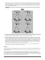
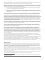
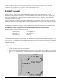
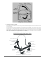
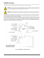
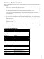
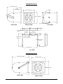
R2SUB
R2SUBZ, R2SUBDF
Premium All-Weather
R-Series Subwoofer System
Installation Guide
EC STATEMENT OF CONFORMITY
This document confirms that the range of products of Community Professional Loudspeakers bearing the CE label meet all of
the requirements in the EMC directive 89/336/EEC laid down by the Member States Council for adjustment of legal
requirements. Furthermore, the products comply with the rules and regulations referring to the electromagnetic
compatibility of devices from 30-August-1995.
The Community Professional Loudspeaker products bearing the CE label comply with the following harmonized or national
standards:
DIN EN 55013:08-1991
DIN EN 55020:05-1995
DIN EN 55082-1:03-1993
The authorized declaration and compatibility certification resides with the manufacturer and can be viewed upon request.
The responsible manufacturer is the company:
Community Light & Sound
333 East 5th Street
Chester, PA 19013
USA
TEL: 1-610 876-3400
FAX: 1-610 874-0190
Chester, PA USA March 2007
FIND THE LATEST ONLINE
Every effort has been made to ensure that the information contained in this manual was complete and accurate at the time
of printing. However, due to ongoing technical advances, changes or modifications may have occurred that are not covered
in this publication. The latest version of this manual and the most recent product information published by Communtiy is
always available at http://www.communitypro.com on the world wide web. The publication date can be found on the rear
cover or last page.
R2SUBZ and R2SUBDF - Installation Guide - Page 2
WELCOME TO COMMUNITY!
Since 1967, Community has been designing and building innovative loudspeaker products for the worldwide sound
reinforcement industry. Founded by Bruce Howze, who remains the principal designer to this day, the company has
achieved numerous ‘firsts’ in technology breakthroughs. Some of these include:
First - fiberglass composite loaded midrange horn for touring systems – the LMF.
First - large-scale fiberglass horns used on Elvis Presley’s 1971 tour.
First - testing and documentation of loudspeakers in a free field acoustical environment.
First - to publish coverage patterns of its loudspeakers, setting the industry standard.
First - mid-range compression driver, the M4.
First - carbon fiber diaphragm compression driver.
First - passive loudspeakers with internal multi-band, multi-level processing.
First - Ferrofluid-cooled professional cone drivers.
First - HF compression driver diaphragm without an outer suspension – the VHF100.
Community’s philosophy is to build products that are uncompromised in sound quality, reliability, durability and flexibility,
all at a fair price. We provide comprehensive technical support and we stand behind every product we manufacture. We
pledge to do our best to insure that you are satisfied with your Community purchase!
R2SUBZ and R2SUBDF - Installation Guide - Page 3
Community R2SUB
Premium All-Weather
R-Series Subwoofer System
Table of Contents
Introduction .................................................................................................. 5 R2SUB Installation Guidelines .......................................................................... 5 Directivity & Positioning .................................................................................. 5 Polarity ......................................................................................................... 6 Absolute Phase .............................................................................................. 7 R2SUBDF Assembly ........................................................................................ 8 R2SUBDF Mounting Instructions ....................................................................... 8 R2SUBZ Assembly ........................................................................................ 11 R2SUB with R2 Yoke Mounting Instructions ...................................................... 12 Maintaining Weather-Resistance ..................................................................... 13 Technical Specifications................................................................................. 13 R2SUB Dimensions ....................................................................................... 14 Warranty Information And Service .................................................................. 15 R2SUBZ and R2SUBDF - Installation Guide - Page 4
Introduction
The Community R2SUB is a powerful dual 12-inch subwoofer system, offering all the weather-resistant features and benefits
of the acclaimed R-Series.
The 400-watt R2SUB subwoofer includes two 12-inch drivers and can be flown or down-fired for flexible system
configuration. Featuring Community’s bulletproof DYNA-TECH protection circuitry, the R2SUB is engineered to provide
quality low frequency reproduction in a wide variety of outdoor and indoor environments. Its weather resistant properties
make it ideal for installation in amusement parks, sports arenas, cruise ships, race tracks and more, while its contemporary
design makes it just as appropriate for indoor installations as well. All R-Series loudspeakers by Community offer
exceptional sound quality - the R2SUB is no exception.
The R2SUB is a true low frequency system that can deliver extreme sonic performance down to 40 Hz. For R-Series based
designs requiring greater LF extension, the R2SUB is available to complement all of Community’s full-range R-Series
loudspeakers. With a smooth fiberglass enclosure in a neutral gray finish and Community’s exclusive three-layer WeatherStop™ grille, the R2SUB is protected by a five-year product warranty and fifteen-year enclosure warranty. Five ½”-13
threaded mounting/rigging points are provided.
Model R2SUBZ includes a weather-resistant yoke mounting bracket.
Model R2SUBDF includes a weather-resistant direct-firing mounting kit.
The TRC400 400-Watt 70/100/140V transformer is available as an optional accessory sold separately.
R2SUB Installation Guidelines
These guidelines are intended to help you optimally locate and install your R2SUB subwoofer(s) in order to get maximum
performance from the system.
Directivity & Positioning
Subwoofers are typically far less directional than the mid-range and high-frequency loudspeakers they will be used with.
This is because low frequency wavelengths are significantly longer than mid-range and high-frequency wavelengths (a 30
Hz wave is approximately 35 feet in length and a 100 Hz wave is approximately 11.3 feet in length). The extremely long
wavelengths cause them to behave quite differently from their shorter mid and high frequency counterparts.
First, long wavelengths do not ‘see’ small or moderate size obstructions as obstacles; they simply diffract around such
barriers as if they’re not there.
Second, the substantial length of low frequency waves makes it difficult to distinguish their source direction. This is why a
single subwoofer can often be used successfully to augment a stereo pair of mid-high loudspeakers without unduly harming
the stereo separation and image.
Third, low frequency waves tend to add together quite graciously, even if their sources are separated by considerable
distances, as long as they are in phase with each other. An example of this is the typical accentuation in low frequency
content that is often experienced in the middle of theatres and concert halls, generated by subwoofers placed far apart on
the opposite sides of the stage.
Overall, the characteristics mentioned above imply that the location of a subwoofer is not particularly critical, and to a
certain extent, this is true. However, there are several factors to consider before you start drilling mounting holes1.
(1) The R2SUB subwoofer will benefit greatly in terms of power output when it’s placed adjacent to one or more boundary
surfaces. If located on the floor or ceiling in a corner (Eighth Space), the R2SUB will produce a full 6 dB more output
than if located in the middle of a floor or ceiling. If located at the junction of two walls (Quarter Space), the R2SUB will
produce 3 dB more output than if it’s located in the middle of a floor. Free Power! What could be better? See Figure
1 for additional clarification.
Model R2SUBDF includes a Direct-Firing Kit that consists of four corner brackets and two support struts. This direct
firing kit allows the R2SUB to be easily attached to a floor, wall or ceiling to take advantage of the boundary surface
effect.
When choosing location(s), be careful not to sacrifice sonic quality for sheer power. If the available wall or corner
location results in the R2SUB being located behind or too close to one or more open microphones, early feedback is
1
A thorough understanding of how low frequency waves transmit in acoustical environments is very helpful when designing and installing
sound systems. We recommend reading “Fundamentals of Sound” and “Psychoacoustics” by F. Alton Everest in the “Handbook for Sound
Engineers” published by Howard Sams & Co.
R2SUBZ and R2SUBDF - Installation Guide - Page 5
likely to occur. If the wall or corner location is too far away from the full-range loudspeaker(s), it may result in the
R2SUB being drastically out of time sync with one or more of the full-range speakers. Sometimes the sound quality of
a wall or corner placement is not desirable, simply due to the room’s acoustical properties. Keep in mind that when
wall and corner locations are appropriate for use, they offer a tremendous increase in power output; however, they
may not always be the best choice.
It’s a good idea to experiment with different locations by conducting listening tests before finalizing the
installation.
Figure 1
(2) Keeping the subwoofer(s) as close as possible to the mid and high loudspeaker(s) will decrease phase irregularities and
time smear. If the subwoofer(s) is placed too far away from the mid/high loudspeaker(s), the listener will experience a
disjointed character to the program material, causing the musicality of the system to suffer.
(3) Although the R2SUB is not highly directional, its acoustical output follows the inverse square law. That is, every time
the distance from the R2SUB to the listener is doubled, the output level will decrease by 6dB. When covering a large
space with multiple R2SUB’s, it may be of benefit to space them some distance apart from one another to even out the
levels throughout the space (typically, this would be done if the mid/high loudspeakers are also spaced apart from one
another, such as in a distributed stadium system). Although spacing will help maintain an even level throughout the
listening space, there may be some areas in between two or more subwoofers that experience a certain amount of
power subtraction caused by destructive interference. Destructive interference occurs when waveforms meet and are
partially or wholly out of phase with each other due to unequal path lengths.
Conversely, if multiple R2SUB’s are located directly adjacent to one another, their power output will add together,
almost seamlessly. This is known as constructive acoustic addition.
Polarity
The correct polarity of the R2SUB subwoofer is a function of its placement in relation to the full-range loudspeaker(s) it will
be used with. This is known as the Phase Relationship of the two systems, though Absolute Phase also plays a role which
will be discussed later.
Depending on the placement of the R2SUB in relation to the full-range loudspeaker(s), as well as the selected crossover
point, the optimal response of the system might be obtained by reversing the phase of either the subwoofer or the fullrange loudspeaker(s). The easiest way to determine the proper phase relationship is to excite the system with a test signal
(such as pink noise) and to view the resultant response on an audio spectrum analyzer. If such equipment is not available,
it is also possible to determine the best phase relationship by careful listening.
R2SUBZ and R2SUBDF - Installation Guide - Page 6
One polarity (either normal or reversed) should result in a discernable cancellation through the crossover region, while the
opposite polarity should result in either a flat response or a peak through the crossover region.
Note: When experimenting to determine the proper polarity, reverse only the full-range loudspeaker(s) or the subwoofer,
never both at the same time. If there is no discernable difference, or a very minimal difference in the measured or audible
response when the polarity is reversed, it indicates one of two things:
(a) The full-range system that the subwoofer is being used with does not reproduce enough low frequency output to
cause either cancellation or addition with the subwoofer, or;
(b) The placement of the subwoofer in relation to the full-range loudspeaker is not optimum. Little or no response
variation will occur if the physical relationship results in an approximate ¼ wavelength of offset at the center of the
crossover frequency.
The solution to (a) is for both systems to remain in positive polarity. No harm will occur if the full-range system simply
does not reproduce enough low frequency energy to compete (either positively or negatively) with the subwoofer’s output.
The solution to (b) is to either change the physical relationship of the two systems, or to delay one of the two systems
(whichever one is positioned closer to the listeners) with a digital delay. A good quality measurement system that can read
and depict phase response or impulse response would be very useful in this situation. However, without such a system, you
can determine an effective delay time by trial and error. Simply increment the delay time in small steps (1 ms) until the
action of reversing the polarity produces maximum cancellation in one orientation and maximum addition in the opposite.
By using a digital delay you will have preserved optimum impulse response and phase response, and you can now filter out
any objectionable mid-bass overlap with an equalizer.
If a delay is not available, it is recommended that either the subwoofer or the full-range loudspeaker be re-located so that
they are closer together and that reversing the polarity of either the subwoofer or the full-range loudspeaker (but not both
at once) will result in a distinct dip at crossover, as discussed above.
If this is impossible due to physical restrictions, the subwoofer and the full-range loudspeaker should be moved further
apart, again until there is a distinct dip at the crossover frequency in one position of polarity. It may take some trial and
error to determine the optimal physical relationship.
Note that in some acoustical situations, the system may sound better when the phase relationship is non-optimum
(resulting in a dip at crossover), than when the crossover region is accentuated by the overlap of the subwoofer and the
full-range speaker(s). However, this is not the best way to achieve a good sounding system. The proper remedy is to
equalize (EQ) the peak at crossover with a parametric equalizer until the response is flat (or until you’ve achieved the tonal
response you desire). Another valid approach is to high-pass the full-range system (typically at 80 – 100 Hz) so that the
overlap with the subwoofer is reduced in magnitude. A third way is to increase the slope of the crossover to 24 dB per
octave or 48 dB per octave (if the crossover has such capability), thereby reducing the bandwidth of the spectrum in which
the two sources overlap.
There is an important reason for this: if the response dip at crossover is due to phase cancellation, the drivers and
amplifiers will be working harder than they should to produce less sound pressure level than they are capable of, because of
the cancellation taking place. All that cancelled energy uses power unnecessarily!
Conversely, if you attenuate the peak at crossover with equalization2, you are reducing the power that’s required to obtain a
given sound pressure level. The result is more available power, more headroom, and far less stress on the drivers.
Once you have either delayed or re-positioned the speakers, you can permanently wire the system in the phase relationship
that produces maximum acoustical addition at crossover, but first read the section below on “Absolute Phase.”
Absolute Phase
Quite a bit has been written about absolute phase, particularly in regard to studio recording and hi-fi sound reproduction.
The subject is, however, often ignored in the field of sound reinforcement. Essentially, positive absolute phase refers to
configuring the system so that the driver(s) moves forward toward the listener, thereby producing a positive wavefront
upon the first cycle of excitation by the source material. For example, at the instant of impact, when the head of the kick
drum moves outward towards the microphone, the speaker cones also move outward.
Obviously, the phase integrity of the entire signal processing chain must be maintained for this to occur. Is absolute phase
audible? Should you be concerned? Yes, it is audible and though subtle, it makes a big enough difference to warrant taking
the time needed to insure that the signal chain is phase-positive throughout. You’ll hear an improvement in sonic impact,
especially in the lower frequencies.
We recommend that absolute phase be kept positive in all low-frequency devices whenever possible. This can be checked
with a small handheld style phase response test unit, available from numerous manufacturers.
2
The three corrective methods referred to in the text (equalizing, high-passing, and increasing the slope of the crossover) are all various
implementations of equalization.
R2SUBZ and R2SUBDF - Installation Guide - Page 7
Although it’s easy to simply reverse the phase of the subwoofer to determine its best phase relationship to the full-range
speaker system, if the best position turns out to be reversed we recommend that you instead reverse the full-range
system(s) so that the subwoofer(s) can remain in a state of positive absolute phase.
R2SUBDF Assembly
The R2SUBDF includes a Direct Firing Mounting Kit that is designed to attach a weather-resistant R2SUB subwoofer
system to the floor, walls, or ceiling in order to take advantage of the surface as an acoustical boundary. Typical
applications include theme parks, sports venues, race tracks, shopping centers, cruise ships, skating rinks, and nightclubs.
Directly firing the R2SUB into an acoustical boundary provides a substantial increase in output level, when compared to
installing the subwoofer in free space.
The kit consists of four stainless steel Mounting Brackets that clamp to each of the four corners of the R2SUB, two stainless
steel Support Struts that provide additional structural integrity when the R2SUB is mounted on a wall or ceiling surface, and
one stainless steel Cable Cover to protect the R2SUB’s attached input cable.
Each of the four Mounting Brackets consists of two parts; the Surface Bracket is first fastened to the mounting surface, then
the Clamp Bracket is attached to the Surface Bracket, thereby securely clamping the R2SUB between the two parts of each
bracket. The Support Struts provide additional support to the R2SUB when it’s mounted on a wall or ceiling. Installation
of the R2SUB on a wall or ceiling should NOT be attempted without the use of the Support Struts.
The following parts are included with the Direct Firing Kit:
Surface Bracket (4)
Clamp Bracket (4)
Cable Cover (1)
Support Struts (2)
3/8-16 x 1" Carriage Bolt (8)
3/8" Flat Washer (8)
3/8" Lock Washer (8)
3/8" Hex Nut (8)
Gasket (4)
Layout Template (1)
Rubber washers, flat washers, lock washers and hex bolts are included on the mounting points of the R2SUB enclosure, and
should be utilized with the Support Struts as needed. No other hardware is provided to install the R2SUB loudspeaker using
the Direct Firing Kit. Such hardware must be supplied by the installer, and should be rated to safely handle the weight load
of the enclosures. The installer is solely responsible for determining if all components that are used to install or suspend the
enclosures are adequately sized and rated, and if the structure they are suspended from is capable of safely supporting the
aggregate weight load.
R2SUBDF Mounting Instructions
1.
First plan the optimum location(s) of the R2SUB(s).
2.
Once you have determined the subwoofer location(s), lay out a square pattern of four holes on 22 1/32” centers
(55.9 cm). See the diagram below. To simplify this operation, a full-size layout template has been provided in the
kit.
R2SUBZ and R2SUBDF - Installation Guide - Page 8
3.
Fasten the Surface Bracket part of each of the four brackets to the mounting surface using a suitable fastener.
Suggested fastener types and minimum sizes are as follows:
Wood: Lag bolts of three-eighths inch diameter (3/8”) or larger, by two-inches (2”) in length (or longer). Metric
equivalent is 10mm x 50mm. Make sure to drill a pilot hole to avoid breaking the lag bolt when tightening.
Steel Panel: 3/6-16 machine bolts (or larger) secured with flat washers, lock washer, and hex nuts. Length as
required. Metric equivalent is 10mm.
Concrete: 3/8” x 3” (or larger) expansion anchors such as HILTI Kwik-Bolt. Metric equivalent is M10 x 75mm.
Note: drilling a hole in concrete typically requires the use of a hammer drill.
IMPORTANT: Fastening the R2SUB to sheetrock, drywall, or plaster surfaces using the Direct
Firing Kit is not recommended!
4.
Place the R2SUB on the four Surface Brackets. Check to make sure that the R2SUB is oriented so that its speaker
input cord is in the most convenient position.
5.
Assemble the Clamp Brackets to the Surface Brackets using the 3/8-16 carriage bolts, flat washers, lockwashers,
and nuts provided. The carriage bolts should be inserted from the outside so that their rounded heads are visible
(see illustrations). Install a flat washer on the threaded end of each of the carriage bolts inside the Surface
Bracket, followed by a lockwasher and a nut. Tighten the nut with your fingers until you cannot turn it any further.
Finish by firmly tightening each nut with a socket and ratchet until the lockwasher is fully compressed
(approximately 12 to 15 foot-lbs).
IMPORTANT: On the corner where the speaker input cable in located, assemble the Cable Cover to the Clamp
Bracket, then the Clamp Bracket to the Surface Bracket, before inserting the carriage bolts. Route the speaker
cable through the bracket as shown in the illustration below. The Cable Cover is designed to protect the cable
from abrasion, as well as to provide a neat looking installation.
R2SUBZ and R2SUBDF - Installation Guide - Page 9
6.
Installation on Walls or Ceilings
If the R2SUB is to be installed on a wall or ceiling, the two stainless steel Support Struts must be utilized to insure
structural integrity.
The two Support Struts should be positioned on two opposite sides of the R2SUB. First, attach the end of a strut
with the hole in it to the Mounting Bracket using the same carriage bolt that holds the two parts of the Mounting
Bracket together. Next, attach the slotted end of the strut to the 1/2–13 threaded insert on the side of the R2SUB
using a 1/2–13 hex head bolt. Repeat the process on the opposite side of the R2SUB with the second Support
Strut. Tighten all fasteners securely (approximately 12 to 15 foot-lbs.).
R2SUB-DFK Assembly Using Support Struts
EXISTING RUBBER WASHER
EXISTING 1/2" FLAT WASHER
EXISTING 1/2"
LOCK WASHER
CABLE COVER
3/8-16x1"
CARRIAGE BOLT
EXISTING 1/2" HEX BOLT
CLAMP BRACKET
GASKET
SURFACE BRACKET
3/8" FLAT WASHER
3/8" LOCK WASHER
3/8-16x1"
CARRIAGE BOLT
SURFACE BRACKET
GASKET
CLAMP
BRACKET
(2) SUPPORT STRUTS
ONE ON OPPOSITE SIDE
NOT SHOWN
3/8" HEX NUT
3/8" FLAT
WASHER
3/8" LOCK WASHER
R2SUBZ and R2SUBDF - Installation Guide - Page 10
R2SUBZ Assembly
The R2SUBZ includes a weather-resistant U-shaped mounting yoke for mounting R2 systems. When properly utilized, the
mounting yoke allows your R2SUB loudspeaker to be properly aimed in virtually any direction.
CAUTION: The R2 Mounting Yoke is specifically designed to provide a high degree of safety in R2 installations.
It is highly recommended for mounting an R2. Other mounting methods should be carefully considered so that
undue strain and possible failure of the mounting points does not occur.
CAUTION: In order to maintain the weather-resistant integrity of an R2, all five rubber washers supplied with
the R2 mounting point hardware must be used and be flush against the enclosure when the R2 is mounted.
The yoke bracket is provided with the hardware required to attach it to the R2SUB enclosure. No additional hardware is
provided to attach the yoke bracket to the mounting surface. Such hardware must be supplied by the installer and should
be sized and rated for the weight load of the loudspeaker
The yoke has three 17/32” (13.5 mm) holes in the crossbar. These holes are intended for attachment of the yoke to the
structure to which the R2SUB is to be mounted. The hardware used for the attachment must be load-rated for the intended
purpose. Also ensure that the structure you are attaching to is capable of supporting the loudspeaker and yoke assembly.
This must include any torque load that may be applied to the structure as a result of the loudspeaker/yoke position and
aiming angle. For outdoor installations wind loading must also be taken into account. It is recommended that a qualified
and licensed structural engineer approve the mounting design.
R2SUBZ and R2SUBDF - Installation Guide - Page 11
R2SUB with R2 Yoke Mounting Instructions
Normally the yoke should first be attached to the R2SUB then the entire assembly mounted to a structure. However in the
some unusual cases it may be desirable to mount the yoke and secure it in place before mounting the R2SUB to the yoke.
Depending on the situation the sequence of the following mounting procedure may have to be modified to facilitate the
work. Nonetheless the instructions and precautions about use of the hardware should still be followed.
1.
To attach the yoke to the R2SUB, first determine whether the yoke will be attached to the sides or top/bottom of
the loudspeaker. This will depend on what the yoke is to be mounted to and how the R2SUB must be oriented
when positioned for proper coverage.
2.
Once the position of the yoke is determined, remove two supplied ½-13 stainless steel mounting bolts, with the
lock, flat, and rubber washers from the mounting points where the yoke is to be attached.
3.
Position the loudspeaker within the yoke making sure that the large rubber washers sit between the yoke and the
enclosure. Be aware this is intentionallymade to be a tight fit. Screw the ½-13 x 2-½” (64 mm) bolts into the
mounting holes using the rubber washers, flat washers, and lock washers removed in step 2. Tighten only enough
so as to allow the yoke to move as needed for the rest of the procedure. The rubber washer has a 7/16” (11 mm)
hole so it fits quite snugly around the mounting bolts to form the weather seal for the R2SUB mounting hole. It
also provides some friction to help hold the yoke in position until completely secured.
4.
Attach the short flat end of the Contour Strap to the mounting point located at the back/center of the enclosure
bell using the bolt, rubber washer, flat washer, and lock washer supplied in the mounting point. Make sure that the
rubber washer is between the Contour Strap and the enclosure. Leave the other end (the long flat end) of the
Contour Strap temporarily unattached. Eventually this will be attached to one of the side mounting points. This
point must be on the side where the crossbar of the yoke will be positioned when the loudspeaker is in its final
mounting location and aimed properly.
5.
Mount the R2SUB and its attached yoke to the structure that will support it. If the center hole on the yoke
crossbar is used as one of the yoke mounting points you need to attach the Securing Strap to this hole at the same
time you mount the yoke to the structure that will hold the R2SUB assembly. In addition to attaching the Securing
Strap to the yoke, the supplied stainless steel ½-13 x 2-½” bolt, ½” flat washers, ½” lock washer and ½-13” hex
nut can be used as a yoke mounting bolt. In any case, the Securing Strap attaches to the yoke using the end of
the Securing Strap with the short bent tab and the 9/16” (14 mm) hole in it. The Securing Strap tab is positioned
on the underside of the yoke crossbar with the long end bent towards the enclosure and positioned over the
Contour Strap.
6.
After properly securing the yoke to the structure, adjust the aiming angle of the R2SUB. Once the aiming angle is
set, bend the Securing Strap against the Contour Strap. The series of holes in the Securing Strap should line up
with one of the three 5/16” (8 mm) holes in the Contour Strap. This determines where to locate the bolt in the
Contour Strap to attach the Securing Strap. Lift the Contour Strap away from the R2SUB enclosure and put the ¼20 x 1” (25 mm) stainless steel bolt in this hole with the bolt head between the Contour Strap and the enclosure.
Secure the bolt to the Contour Strap with one of the supplied ¼” lock washers and ¼-20 hex nuts.
7.
Attach the free end of the Contour Strap to the mounting point on the side of the R2SUB enclosure using the ½” –
13 bolt, rubber washer, flat washer and lock washer supplied with the R2SUB mounting point. Make sure that the
rubber washer is located between the Contour Strap and the enclosure.
8.
Attach the Securing Strap to the ¼-20 bolt installed on the Contour Strap in step 8. Use the hole in the Securing
Strap nearest to the bolt when the R2SUB is at the proper aiming angle. You will have to bend the Securing Strap
towards the enclosure to put it on the bolt which is normal. First place one of the ¼” flat washers on the bolt, then
the Securing Strap on the bolt. Finish with the remaining ¼” flat washer, ¼” lock washer then ¼-20 nut.
9.
Firmly tighten the bolts holding the yoke to the R2SUB enough so seat the lock washer. Be careful not to overtighten as, given the size wrench that typically will be used, it is possible to apply excessive torque.
10. Lastly ensure that all the attachment bolts for the Contour and Securing Straps are securely tightened.
Caution: Any of the mounting bolts supplied with the R2SUB that are not used for mounting must be left
in place with their rubber washers and firmly tightened to maintain the integrity of the weatherproofing.
R2SUBZ and R2SUBDF - Installation Guide - Page 12
Maintaining Weather-Resistance
There are several things that must be observed when installing an R2SUB in order to maintain its weather-resistant integrity
for outdoor use.
1.
Always orient the loudspeaker so the mouth of the horn is, at a minimum, pointing slightly downward. Failure to
do this will result in water collecting inside the bell of the horn.
2.
When handling an R2SUB be careful not to scratch or scrape the powder coat finish on the perforated metal grille.
This finish on the grille protects the steel from corrosion. If the finish is scratched or otherwise cut into in any way,
the underlying steel will corrode at the point where the integrity of the finish has been violated.
3.
All five mounting holes must be sealed off with the stainless steel bolts, washers, and rubber washers supplied. If,
for any reason, these bolts must be removed, seal off the hole with silicone caulking or some other suitable
weather-tight sealant.
4.
The rubber washers supplied with the mounting bolts must always seat against the enclosure.
5.
The gland-nut securing the loudspeaker cable to the enclosure is sealed at the factory. Do not attempt to remove
this nut or the weather-tight seal will be broken. If it is desired to replace the gland-nut with a jack, the jack must
be a weatherproof design. It must be suitably sealed to the enclosure with silicone caulk or some other suitable
weather-tight sealant.
6.
The grille assembly is designed to prevent normal and wind-driven rain from directly entering the mouth of the
loudspeaker. The grille is not designed to withstand such things as being directly sprayed from a hose; therefore
this should be avoided.
7.
If you use any hardware in place of the stainless steel screws, bolts, nuts and washers supplied, it should also be
made of stainless steel.
Caution: If the above instructions are not observed, the weather-resistant integrity of an R2SUB can be compromised. This
can result in damage to or failure of the hardware or internal components.
Technical Specifications
Loudspeaker Model
R2SUB
Loudspeaker Type:
Weather-resistant subwoofer system
Operating Range:
30 Hz - 500 Hz
40 Hz - 150 Hz (±2dB)
Maximum Input Ratings:
400W Continuous / 1000W Program
Recommended Amplifier Power:
830W to 1200W @ 4 Ohms
Sensitivity 1W/1m:
92 dB SPL
Maximum Output:
118 dB SPL
Nominal Impedance:
4 Ohms
Minimum Impedance:
3.5 Ohms @ 100 Hz
Nominal –6dB Beamwidth:
360° H x 180° V
Recommended Signal Processing:
35 Hz 24dB/Octave high pass filter
Drivers:
LF (2) 12” Cool-Coil™
Driver Protection:
DYNA-TECH protection circuitry
Input Connection:
12-foot (4 m) SJOW #16 Gauge
Controls:
None
Enclosure:
Hand laminated fiberglass
Finish:
Light grey gel-coat
Mounting/Rigging Provisions:
(5) 1/2-13 rigging points
Grille:
3-layer WeatherStop™, light grey
(Zinc-rich epoxy dual-layer powder coated perforated
steel grille, foam, woven poly mesh)
Required Accessories:
Electronic high pass filter
Supplied Accessories:
R2SUBZ includes R2 U-shaped mounting yoke
R2SUBDF includes DFKIT direct firing kit
Optional Accessories:
TRC400 400-watt transformer
Digital signal processor
Dimensions (H x W x D):
24.75" x 24.75" x 30.75" (629 x 629 x 781 mm)
Weight (without yoke or DFKIT):
69 lbs (31.3 kg)
R2SUBZ and R2SUBDF - Installation Guide - Page 13
R2SUBZ Dimensions
30.75" [781.05]
17.25"
[438.15]
24.75" [628.7]
YOKE
24.75" [628.7]
(5) 1/2-13THREAD
SIDE VIEW
TOP VIEW
FRONT VIEW
3.622" [92]
.236" [6]
(TYP)
7.992"
[203]
7.992"
CL [203]
1.220" [31]
∅.532" [∅13.5]
(TYP 7 PLACES)
16.693±.079"
[424±2]
.472" [12]
1.220" [31]
(TYP)
1.260" [32]
21.000" [533.4]
R2 YOKE
R2SUBDF Dimensions
32.750" [831.86]
25.000" [635]
25.000" [635]
SIDE VIEW
FRONT VIEW
R2SUBZ and R2SUBDF - Installation Guide - Page 14
Warranty Information And Service
Transferable Warranty (Limited) – Valid in the USA Only
Community loudspeaker systems are warranted in the USA to be free from defects in materials and workmanship for a period of five
years, as determined by one of the following two methods, whichever is longer:
1.
Starting from the date of retail purchase, as noted on the sales receipt from an authorized Community dealer,
OR
2.
Starting from the date of manufacture, determined by the serial number, if the sales receipt is not available.
This warranty applies to the product; therefore, the remainder of the warranty period will be automatically transferred to any
subsequent owner.
This warranty applies only to failure of a Community loudspeaker caused by defects in materials and workmanship during the stated
warranty period. It does not apply to a unit that has been subjected to abuse, accident, modification, improper
handling/installation, or repairs made without factory authorization or by anyone other than authorized Community Field Service
Stations. This warranty is void if the serial number has been defaced, altered or removed.
Products covered by this warranty will be repaired or replaced at the option of Community, without charge for materials or labor,
provided all the terms of this warranty have been met.
Obtaining Warranty Service
Warranty service may be obtained from the factory, or from an authorized Field Service Station.
To obtain factory or field warranty service for products purchased in the United States, return the product for inspection to the
address below, freight prepaid, in the original packaging. If the original packaging is not available, call or write Community
Warranty Service to obtain proper packaging materials or hand carry the product to the nearest Field Service Station.
Factory Service Center:
Community Warranty Service
333 East Fifth Street
Chester, PA 19013-4511 USA
Field Service Station:
Call (610) 876-3400 for the nearest Authorized Field Service Station
For factory service, please call (610) 876-3400 for a Return Authorization (R/A) number before shipping. The following information
must be included in the package:
1.
Owner’s complete name, daytime phone number, return street address and return authorization number.
2.
The serial number of the product being returned and a copy of the retail sales receipt, if possible.
3.
A complete description of the problem(s) experienced, including a brief description of how the equipment is being
used and with what brand, model and output power of amplifier.
Upon receipt, the service center will determine if the problem is covered under warranty. If covered under this warranty, the
product will be repaired or replaced, at Community’s option, and returned to the owner freight prepaid. If the problem is not
covered under this warranty, the owner will be notified of the problem with an estimate of the repair costs.
Consequential and Incidental Damages: Community shall not be liable for any consequential or incidental damages including,
without limitation, injury to persons, property, or loss of use. Some states do not allow the exclusion or limitations of consequential
or incidental damages, so the above limitations and exclusions may not apply.
This Community warranty is not extended by the length of time which an owner is deprived of the use of the product. Repairs and
replacement parts provided under the terms of this warranty shall carry only the remaining portion of the warranty.
Community reserves the right to change the design of any product from time to time, without notice and with no obligation to make
corresponding changes in products previously manufactured.
While this warranty gives specific legal rights, there may also be other rights that vary from state to state. No action to enforce this
warranty shall be permitted ninety days after expiration of the warranty period.
Warranty Information and Service for Countries Other Than The USA
To obtain specific warranty information and available service locations for countries other than the United States of America, contact
the authorized Community Distributor for your specific country or region.
R2SUBZ and R2SUBDF - Installation Guide - Page 15
Community Professional Loudspeakers
333 East Fifth Street, Chester, PA 19013-4511 USA
Tel: (610) 876-3400 | Fax: (610) 874-0190
www.communitypro.com
© 2009 All Rights Reserved
02DEC2009