1
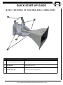
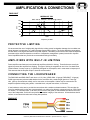
RMG-200A
RMG-200AT
INSTALLATION / OPERATION
MANUAL
Weather-Resistant,
High-Output, Loudspeaker Systems
EC STATEMENT OF CONFORMITY
E C S TAT E M E N T O F C O N F O R M I T Y
This document confirms that the range of products of Community Professional Loudspeakers bearing the CE
label meets all of the requirements in the EMC directive 89/336/EEC laid down by the Member States Council for
adjustment of legal requirements. Furthermore, the products comply with the rules and regulations referring to
the electromagnetic compatibility of devices from 30-August-1995.
The Community Professional Loudspeaker products bearing the CE label comply with the following harmonized
or national standards:
DIN EN 55013:08-1991
DIN EN 55020:05-1995
DIN EN 55082-1:03-1993
The authorized declaration and compatibility certification resides with the manufacturer and can be viewed upon
request. The responsible manufacturer is the company:
Community Light & Sound
333 East Fifth Street
Chester, PA 19013
USA
TEL: 1-(610) 876-3400
FAX: 1-(610) 874-0190
Chester, PA USA March 2011
FIND THE LATEST ONLINE
Every effort has been made to ensure that the information contained in this manual was complete and accurate at
the time of printing. However, due to ongoing technical advances, changes or modifications may have occurred
that are not covered in this publication. The latest version of this manual and the most recent product information
published by Community is always available at http://www.communitypro.com.
Community RMG-200A and RMG-200AT Installation / Operation Manual — Page 2
WELCOME TO COMMUNITY
A T R AD I T I O N O F E X C E L L E N C E AN D
I N N O VAT I O N . . . S PAN N I N G M O R E T H AN 4 0 Y E AR S !
Since the founding of our company in 1968, Community has been a constant developer and innovator of
loudspeaker technology. Many of our engineering achievements were undertaken to solve problems, when no
prior solutions existed, while others were the result of simply seeing a better way to do things.
Over the years our technologies have been imitated, and our methods have become common practice
throughout the professional sound industry. However, developments like carbon fiber diaphragm compression
drivers still stand alone, and well ahead of the competition. Just a few of Community’s unique accomplishments
include the following:
First successful fiberglass mid-frequency, high-frequency, and large-format bass horns.
First compression loaded mid-range horn for touring systems - the LMF.
First suspension-less diaphragm HF driver - the VHF100.
First mid-range, full-decade (200 Hz - 2 kHz) high-power compression driver - the M4.
First carbon fiber diaphragm compression drivers - M4, EM280, EM282.
First Ferrofluid-cooled professional woofers - the VBS Series.
First product series with all drivers Ferrofluid-cooled.
First air-cooled loudspeakers for touring systems - AirForce.
First three-way cinema loudspeaker systems - Paramount Executive Studio Theatre, Warner Bros.
screening theatre and dubbing rooms.
First electro-acoustic system to equal the sound level of pneumatic warning sirens.
First to provide loudspeaker coverage over an entire country - Denmark Emergency System.
First comprehensive, calibrated data acquisition of sound reinforcement products.
First integral signal-aligned three-way sound reinforcement systems - RS Series.
First pro audio company with an Internet Web site.
First all horn-loaded, high-fidelity, weather-resistant loudspeakers - R2 Series.
In line with our history of excellence and innovation, each Community product is manufactured in accordance
with a complicated and exacting chain of procedures that ensure absolute quality and uniformity.
With our unique designs, our sophisticated techniques, and our proprietary materials and transducers, we are
committed to bringing only the finest audio products to the many thousands of professional sound engineers,
performers, and end users who rely on them daily.
Community Professional Loudspeakers
333 East Fifth Street
Chester, PA 19013-4511 USA
TEL: 1-(610) 876-3400 FAX: 1-(610) 874-0190
www.communitypro.com
© 2011 All Rights Reserved
Community RMG-200A and RMG-200AT Installation / Operation Manual — Page 3
TABLE OF CONTENTS
TO P I C S
EC Statement of Conformity .................................................................................................... Page 2
Welcome to Community .......................................................................................................... Page 3
Important Safety Information ................................................................................................... Page 5
Unpacking, Inspection, and Damage Claims ........................................................................... Page 6
Introduction / Features ............................................................................................................ Page 7
Product Descriptions .............................................................................................................. Page 8
Quick Start-up Guide / Basic Features .................................................................................... Page 9
Signal Processing ................................................................................................................. Page 10
Power Amplification ...................................................................................................... Pages 10 - 11
Use of Protective Limiting ...................................................................................................... Page 11
Electrical Installation / Connecting to the Loudspeaker................................................. Pages 11 - 12
Mounting Point Dimensions ................................................................................................... Page 13
Mechanical Installation ........................................................................................................ Pages 14
Technical Specifications ........................................................................................................ Page 15
System Optimization ............................................................................................................. Page 16
In Case of Difficulty ............................................................................................................... Page 17
Warranty / Service Information .............................................................................................. Page 17
The Complete R-Series Family.............................................................................................. Page 18
R-Series Operating Distances ............................................................................................... Page 19
Contact Information ............................................................................................................... Page 20
Community RMG-200A and RMG-200AT Installation / Operation Manual — Page 4
IMPORTANT SAFETY INFORMATION
I M P O R TAN T S AF E T Y I N F O R M AT I O N
Always follow these basic safety precautions when using or installing R-Series loudspeakers and accessories:
Read these instructions.
Keep these instructions.
Heed all warnings.
Follow all instructions, particularly those pertaining to rigging, mounting, suspension of the product, and electrical
connections.
The terms IMPORTANT, CAUTION, and DANGER are used throughout this manual to alert the reader to
important safety considerations. If you have any questions or do not understand the meaning of these terms, do
not proceed with installation. Contact your local dealer, distributor, or call Community directly for assistance.
These terms are defined below:
IMPORTANT: describes an operating condition or user action that may expose the equipment or
user to potential damage or danger.
CAUTION: describes an operating condition or user action that will likely cause damage to the
equipment or injury to the user or to others in the vicinity.
DANGER: describes an operating condition or user action that will immediately damage the
equipment and/or be extremely dangerous or life threatening to the user or to others in the
vicinity.
R I G G I N G AN D E L E C T R I C AL S AF E T Y
DANGER: The loudspeakers described in this manual are designed and intended to be
‘flown,’ mounted, or suspended for maximum acoustical performance using a variety of
rigging hardware, means, and methods. Installation of the loudspeakers should only be
performed by trained and qualified personnel. It is strongly recommended that a licensed
and certified professional structural engineer approve the mounting design. Severe injury
and/or loss of life may occur if these products are improperly installed.
DANGER: R-Series rigging fittings are rated at a Working Load Limit (WLL) of 100 lbs.
(45.4 kg) with a 10:1 safety margin. No single rigging fitting should ever be subjected to a
load that is greater than this stated limit. Failure to heed this warning could result in severe
injury and/or loss of life.
IMPORTANT: Refer to the sections on installation and connections later in this manual for additional
information on rigging and electrical safety.
IMPORTANT: The stainless steel mounting bolts that mount the yoke must be kept in place to seal
the enclosure from air leaks. If the rigging fittings do not remain sealed, air leaks will occur in the
enclosure that will compromise the loudspeaker’s weather-resistance and its low frequency
performance.
Community RMG-200A and RMG-200AT Installation / Operation Manual — Page 5
UNPACKING
U N PAC K I N G AN D I N S P E C T I O N
R-Series loudspeakers are inherently rugged and are carefully packed in sturdy cartons. However, it is wise to
thoroughly inspect each unit after it has been removed from the packaging, as damage may have occurred
during shipping.
S H I P P I N G C L AI M S
Please note that once the shipment has left your dealer or the Community factory, the responsibility for damage
is always borne by the freight company. If damage has occurred during shipping, you must file a claim directly
with the freight company. It’s very important to contact the freight company as soon as possible after receiving
your shipment, as most freight companies have a short time limit within which they will investigate claims.
Make sure to save the carton and the packing materials, as damage claims can be denied if these materials are
not retained. If there is evidence of physical damage to the carton upon arrival, be very careful before signing a
delivery receipt. Often, the fine print in a delivery receipt will waive your right to file a claim for damage, or loss,
after you sign it.
Your Community dealer and the factory will try to help in any way they can, but it is the responsibility of the party
receiving the shipment to file the damage claim. This is a provision of law in the USA and in most countries.
It’s always a good idea to retain the carton and packing materials indefinitely, if possible, in the event that the
product may need to be returned to your dealer or distributor for repair in the future.
W H AT ’ S I N T H E B O X
Each shipping carton contains the following items:
(1) RMG-200A
or
(1) RMG-200AT
(1) Swivel Yoke-style Bracket (Fully assembled and attached to RMG-200A/RMG-200AT loudspeaker.)
(1) Installation/Operation Manual
(1) Warranty Card
P U R P O S E O F T H I S M AN U AL
This manual is intended to help you install and use the RMG-200A and RMG-200AT loudspeakers safely and
effectively. It provides useful information to help you obtain the best performance, sound quality, and reliability
from these systems.
We’ve provided a Quick-Start diagram to enable you to install and operate the products immediately, but we
recommend that you read this manual in its entirety to ensure that your installation meets the highest possible
quality standards.
Community RMG-200A and RMG-200AT Installation / Operation Manual — Page 6
INTRODUCTION / APPLICATIONS
I N T R O D U C T I O N TO R M G L O U D S P E AK E R S
All-Weather, All-Purpose
The RMG-200A and RMG-200AT are complete horn/driver systems designed for use in stand-alone voice-range
sound reinforcement and announcement/signaling applications. The are designed to handle the harshest
outdoor environmental conditions, but are often the ideal choice for indoor environments as well.
Both models are fully horn-loaded, manufactured from hand-laid fiberglass, and powered by Community’s
industry-leading electro-mechanical drivers. Horn-loading provides the highest possible efficiency, excellent
transient response, and predictable pattern control - all of which equate to superior performance.
Fiberglass construction ensures that these loudspeakers can withstand continual exposure to the elements and
are free from the decomposition that can occur over time with wood-based products.
Community’s proprietary driver technology provides excellent sonic quality and is engineered for durability and
longevity. The driver in both RMG models exhibits exceptional resistance to potentially damaging environmental
conditions, as do the enclosures themselves. Both models meet the needs of numerous applications, some of
which are listed below:
TYPICAL APPLICATIONS
Stadiums
Voice Warning Systems
Industrial Paging
Athletic Fields (football, soccer, baseball, tennis)
Sports Arenas
Racetracks & Motor Speedways
Gymnasiums & Field Houses
Theme Parks and Amusement Parks
Swimming Pools and Water Parks
Ski Slopes
Cruise Ships
Fairgrounds
Rodeos
Air Shows
Skating Rinks
Convention Centers
Factories & Warehouses
Please see our comprehensive 60 page R-Series Application Guide at www.communitypro.com/rseries
for advice and information on how to best utilize the R6-51 and R6-BASSHORN, as well as how to utilize
other R-Series loudspeakers. The Guide contains a wealth of knowledge, along with numerous
examples of successful installations.
Community RMG-200A and RMG-200AT Installation / Operation Manual — Page 7
PRODUCT DESCRIPTION
P R O D U C T D E S C R I P TI O N
The RMG-200A and RMG-200AT provide focused, high output sound projection, with predictable performance
and exceptional long-term durability.
The horn portion of the assembly is a handcrafted one-piece waveguide, precision molded of hand-laminated,
fiber-reinforced glass for optimum performance. Substantial fiberglass layering, and an integral throat and driver
flange construction can withstand substantial torque loads. The inherent strength and rigidity of the fiberglass
construction enhances sonic efficiency by preventing sound energy loss, as well as providing inherently
weatherproof fabrication.
The RMG-200AT is a variant of the RMG-200A, but equipped with a high-power, low distortion 75W autoformer
for 70V or 100V operation.
PRODUCT FEATURES
2-inch (51 mm) throat exit M200 driver, Ferrofluid-cooled
High efficiency
High power output
Non-metallic diaphragm eliminates ‘ringing’ and harmonic distortion
Swivel yoke bracket included
Highly resistant to harsh environments, IP65 rating with a minimum 5-degree downward aiming angle
DRIVER DESIGN
The compression driver is a high output, high sensitivity loudspeaker that is configured with the diaphragm
facing forward, isolating the voice coil and magnetic structure from the environment. The one-piece, nonmetallic diaphragm and suspension offers exceptional resistance to the effects of humidity, dust, and corrosive
atmospheres. The large area and low compression phase plug loading, coupled with a massive magnet
structure, exhibits extremely low distortion at high outputs, while maintaining high efficiency and low power
compression. A fiberglass rear cover protects the driver from the effects of weather and corrosion.
A factory-installed weather-resistant steel swivel yoke bracket is included. We proudly offer a five-year warranty
providing protection against manufacturing defects on all components of the system.
H I G H - PAS S F I LT E R
The RMG-200A and RMG-200AT are horn-loaded loudspeaker systems with a specified low frequency response
of 400 Hz. Any attempt to reproduce significant levels below this frequency can result in over-excursion of the
driver. For this reason, a 400 Hz 24dB-per-octave electronic high-pass filter must be employed to protect the
driver from low frequency content below 400 Hz.
Community RMG-200A and RMG-200AT Installation / Operation Manual — Page 8
QUICK START-UP GUIDE
B AS I C F E AT U R E S O F T H E R M G - 2 0 0 A & R M G - 2 0 0 AT
FEATURE
DESCRIPTION
1
Bracket Strap Attachment Points
Eight total; two on each side, and two each on the top and bottom surfaces.
2
Yoke Bracket
Attaches to the bracket straps.
3
Bracket Clamp Bar
Secures the loudspeaker’s angular adjustment.
Community RMG-200A and RMG-200AT Installation / Operation Manual — Page 9
SIGNAL PROCESSING & AMPLIFICATIONS
E Q U AL I Z AT I O N
Small amounts of frequency boost can brighten-up the higher frequencies and round out the lower frequencies,
but they should be restricted to no more than approximately +3 dB in order to avoid damage to the drivers.
Equalization cuts can be very effective for removing the effects of room resonance and other unwanted
acoustical artifacts, but here again should be kept to a minimum. Extreme EQ cuts (or attenuation) will not
cause driver damage, but should be used with discretion to avoid acoustic ‘holes’ in the audible spectrum.
External equalization can be used to "voice" the loudspeaker for particular applications and is especially
effective in attenuating feedback-prone frequencies.
CAUTION: Do not attempt to boost frequencies at, or below 400 Hz with an equalizer (either graphic or
parametric). This will counteract the effect of the high-pass filter discussed above, potentially causing
damage to the driver.
P O W E R AM P L I F I C AT I O N
Power amplifiers used with the RMG-200A and RMG-200AT should be capable of providing enough power to
properly drive the loudspeaker without the amplifier entering into a state of clipping.
Clipping occurs when an amplifier runs out of power. The peaks of the reproduced waveform begin to ‘clip’
and resemble a square wave instead of the typical sine waves and saw-tooth waves that form the basis of most
speech and music. Clipping leads to rapid driver failure because the driver is no longer moving as it’s intended
to. When power is flowing into a driver, but movement is limited because of amplifier clipping, much of the
energy is converted to heat which will soon cause the driver’s voice coil to burn out. As a rule, it is better to use
an amplifier with more power than is necessary, rather than one that has less power than necessary.
Recommended amplifier power for the RMG-200A and RMG-200AT is 100W to 140W per channel for each
loudspeaker. In a system that employs multiple units, the amplifier’s power rating must be scaled upwards by the
number of units in the system (for 70.7V/100V systems)
Normal practice for the RMG-200A is to connect multiple loudspeakers in a parallel circuit. As more units are
added, the load impedance presented to the amplifier will decrease. Care should be taken to ensure that the
combined load of multiple units does not decrease below the amplifier’s rated minimum impedance, which for
most amplifiers is either 4 ohms or 2 ohms. Below is a table to help calculate total load impedance of multiple
units powered by a single amplifier channel.
RMG-200A
No. of Units
Impedance
1
2
3
11
5,5
3.9
4
2.75
5
2.2
6
1.83
7
1.57
Community RMG-200A and RMG-200AT Installation / Operation Manual — Page 10
8
1.375
AMPLIFICATION & CONNECTIONS
RMG-200AT
IMPEDANCE 75W
175
Min Z 400 Hz - 8000 Hz = 70.5 Ohms @ 1790 Hz
Ohms
150
125
100
75
50
100
1,000
10,000
Frequency in Hertz
PROTEC TIVE LIMITING
We recommend the use of a high quality signal limiter to help prevent loudspeaker damage due to sudden transients (dropped microphones, etc.) and/or damage from amplifier clipping. The limiter should be connected as
the last device in the signal chain before the power amplifier. Alternately, most modern DSP based loudspeaker
processors (also called loudspeaker controllers or loudspeaker management systems) have built-in dynamic
control capabilities that can provide the recommended limiting functionality.
AM P L I F I E R S W I T H B U I LT - I N L I M I T I N G
Power amplifier manufacturers have introduced amplifiers with built-in limiting. These limiters are usually designed to prevent the amplifier from clipping. This type of limiting is acceptable to use in lieu of a stand-alone
limiter because it is easy to set-up, is specifically designed for the amplifier, and in most cases is tamper-proof.
This assumes that the amplifier output is sized as recommended.
C O N N E C T I N G T H E L O U D S P E AK E R
The RMG-200A and RMG-200AT each have a 12 ft (3.6m) (RMG-200A :16 gauge, RMG-200AT: 18 gauge)
SJOW-type neoprene jacketed cable attached to the enclosure with a weather-tight gland-nut. These pigtails’ (as they are sometimes called), are for connection to the amplifier. Cables may be connected to the
amplifier’s speaker cabling using solder, a terminal block, crimped connections, or wire-nuts.
If used outdoors, make sure to provide the connections with a weather-resistant treatment. This can take the
form of a weatherproof junction box (recommended) or a coating of a dielectric compound, such as “CRC Dielectric Grease,” or a similar product. In all cases, do not remove the gland nut that attaches the cable to the lower
rear of the loudspeaker, as this will compromise the weather integrity of the enclosure. All terminations should
conform to local electrical codes and industry best practices.
RMG200AT
(75W/70.7V)
Community RMG-200A and RMG-200AT Installation / Operation Manual — Page 11
ELECTRICAL INSTALLATION
RMG200AT
(75W 100V)
Connector Cable Polarity:
The white jacketed conductor is the positive or + signal wire and the black is the negative or – signal wire.
Positive voltage applied to the + wire produces positive acoustic pressure at the mouth of the loudspeaker.
L O U D S P E AK E R C AB L E
The resistance of the cable that connects the loudspeaker to the amplifier will affect the performance of the
loudspeaker. Cable with too high of a resistance will cause power losses and impair the frequency performance
of the system by reducing the electrical damping factor. To minimize these issues it is desirable to keep the
total cable resistance under 0.2 ohm. However, for lengths over 100 feet, the wire gauges needed to meet this
requirement are usually not a practical choice for both physical and cost reasons. Therefore #10 AWG
(American Wire Gauge) is recommended as the most practical gauge for installations that require 100’ (or greater) distances.
Both stranded and solid conductors are acceptable, although cable with stranded conductors is often easier to
work with. The length of both conductors has been calculated into the total resistance in the table shown below.
Note that the lower the gauge number, the larger the wire size.
It is always desirable to locate amplifiers as close to the loudspeakers as possible, thereby minimizing the cost
of the loudspeaker cable, as well as reducing the inherent electrical losses that result from long cable runs.
When installed outdoors, cable insulation should be resistant to water, temperature, and ultraviolet exposure.
Recommended cable compositions include polyethylene, neoprene, Teflon™, Silicon™, and Hypalon™.
Cable compositions that are NOT recommended are Rubber, PVC, polypropylene, polyurethane, and nylon.
Run Length
Minimum Wire Gauge
(American Wire Gauge)
Total Resistance
10 ft. (3m)
16 AWG
0.08 ohm
25 ft. (8m)
14 AWG
0.13 ohm
50 ft. (15m)
12 AWG
0.16 ohm
75 ft. (25m)
10 AWG
0.15 ohm
100 ft. (30m)
10 AWG
0.20 ohm
200 ft. (60m)
10 AWG
0.40 ohm
300 ft. (90m)
10 AWG
0.60 ohm
400 ft. (120m)
10 AWG
0.80 ohm
500 ft. (150m)
10 AWG
1.00 ohm
Recommended Wire Gauge vs. Distance
Community RMG-200A and RMG-200AT Installation / Operation Manual — Page 12
MOUNTING DIMENSIONS
RMG-200A and RMG-200AT MOUNTING DIMENSIONS
RMG-200AT - 18 gauge, 5 conductor, 12’ (3.6m) SJOW cable
NOTE: The gland-nut should be at the bottom when installing the loudspeaker. It is also
advisable to leave a “drip loop” so water will not migrate toward the loudspeaker.
Community RMG-200A and RMG-200AT Installation / Operation Manual — Page 13
MECHANICAL INSTALLATION
S S Y R M G S W I V E L YO K E B R AC K E T
The RMG-200 and RMG-200AT come equipped with a factory-installed galvanized steel yoke-style bracket
attached to the loudspeaker. The bracket is designed to provide an easy and safe method of mounting an RMG
loudspeaker to a fixed mounting surface. The assembly is capable of providing two-axes of motion, rotation and
tilt, if installed using a single center attachment bolt to secure the yoke to the mounting surface.
The brackets are manufactured of galvanized steel and the fasteners are stainless steel in order to resist rust
and degradation from inclement weather when installed in outdoor environments.
Please note that no hardware is provided to attach the yoke bracket to the mounting surface. Such hardware
must be supplied by the installer and should be sized and rated for the weight load of the RMG-200A (20 lbs /
9kg) - or the RMG-200AT (22 lbs. / 9.9 kg with the internal autoformer).
When planning the installation, careful consideration should be given to stress from wind-load or other external
forces
The installer is solely responsible for determining that the mounting hardware is adequately sized and rated, and
if the supporting structure to which the RMG-200A or RMG-200AT is attached, is capable of safely supporting
the weight of the horn/driver/yoke assembly, as well as wind loads, other external forces (such as seismic
activity), and the torsional forces that may result from adjusting the focus of the loudspeaker during installation.
The community PMB1-RR and PMB2-RR may be suitable for pole mounting of the RMG Systems in many
cases. Consideration should be given to expected wind and mechanical stresses when selecting a mounting
system. Please see page five.
INSTRUCTIONS
1. The yoke bracket is fully assembled and attached to the RMG-200A or RMG-200AT loudspeaker and ready
to install to your ceiling, wall, pole, or other mounting surface. Use hardware that is appropriately sized and
rated to handle both the static and dynamic weight load.
2. After mechanical installation, connect the RMG-200A or RMG-200AT to a suitable power amplifier.
IMPORTANT! Make sure that the output of the amplifier is high-passed at 400 Hz with a 24 dB/octave filter!
While listening to program material, adjust the focus until you obtain the desired acoustical coverage. When
satisfied, firmly tighten (10mm x 25 stainless steel bolts, the two pivot bolts), and the two clamp bar bolts. A
torque of approximately 15 foot-lbs. should be sufficient to secure the loudspeaker and maintain the chosen
angle.
3. Often, installations are performed using only a single fastener in the center hole of the yoke bracket. This
allows the installer to rotate the loudspeaker as well as pivoting it. If you have installed the RMG-200A or
RMG-200AT in this manner, we strongly recommend adding two additional fasteners in the remaining two
holes of the bracket for safety, after achieving the desired acoustical focus.
4. In many situations, a back-up safety cable is required to ensure that the loudspeaker will not create a safety
hazard in the event that one or more of the primary mounting components fail. We strongly recommend the
use of safety cables for all installations. Mounting surfaces that appear to be solid can later become unstable
when subjected to external forces, or to degradation over time.
Community RMG-200A and RMG-200AT Installation / Operation Manual — Page 14
TECHNICAL SPECIFICATIONS
Model:
RMG-200A
RMG-200AT
Weather resistant voice-range horn system
Weather resistant voice-range horn system
400 Hz to 8 kHz
400 Hz to 8 kHz
500 Hz to 4 kHz (± 3.5dB)
500 Hz to 4 kHz (± 3dB)
Max Input Ratings:
75W continuous, 120W program
75 / 38 / 19 / 9 watt autoformer taps @ 70V
Sensitivity 1W/1m:
115 dB SPL
(400 Hz to 4 kHz 1/3 octave bands)
114 dB SPL
(400 Hz to 4 kHz 1/3 octave bands)
Maximum Output:
134 dB SPL / 141 dB SPL (peak)
133 dB SPL / 140 dB SPL (peak)
Nominal Impedance:
11 ohms
72 ohms (75W tap @ 70V)
Minimum Impedance:
10.8 ohms @ 1.8 kHz
70.5 ohms @ 1.8 kHz (75W tap @ 70V)
100W to 140W (per unit)
100W to 140W (per unit)
400 Hz high-pass filter 24dB/octave
400 Hz high-pass filter 24dB/octave
50°H (+-4° / -9°, 2 kHz to 4 kHz)
40°V (+10° / -10°, 2 kHz to 4 kHz)
50°H (+-4° / -9°, 2 kHz to 4 kHz)
40°V (+10° / -10°, 2 kHz to 4 kHz)
35 / 15.4, 2 kHz to 4 kHz
35 / 15.4, 2 kHz to 4 kHz
None
None
Loudspeaker Type:
Operating Range:
Recommended
Power Amplifier:
Required Signal
Processing:
Nominal –6dB
Axial Q / DI:
Driver Protection:
Input Connection: 16 gauge. 2 conductor, 12 foot SJOW cable
through gland nut
Environmental IEC529 IP65W rating with a minimum 5-degree
Performance: downward aiming angle
Supplied Accessories: Swivel Yoke Bracket (attached)
Dimensions—Height:
Width (front):
Width (rear):
Depth:
9.75 inches (248 mm)
17.63 inches (448 mm)
10.5 inches (267 mm)
25 inches (635 mm)
Weight (with bracket): 21 lbs (9.5 kg)
Shipping Weight: 27 lbs (12.2 kg)
18 gauge, 5 conductor, 12 foot SJOW cable through
gland nut
IEC529 IP65W rating with a minimum 5-degree downward aiming angle
Swivel Yoke Bracket (attached)
9.75 inches (248 mm)
17.63 inches (448 mm)
10.5 inches (267 mm)
25 inches (635 mm)
24.3 lbs (11 kg)
30 lbs (13.6 kg)
Please note that specifications are subject to change without notice.
Community RMG-200A and RMG-200AT Installation / Operation Manual — Page 15
SYSTEM OPTIMIZATION
COMMISSIONING THE SYSTEM
Commissioning is the process of optimizing the performance of a sound system after it has been installed. There
are several important steps in commissioning a system; these include the following:
1. Verifying the proper operation of each system component:
a) Every source such as mixers, microphones, CD players, audio feeds from other locations, and so on,
should be tested independently of the newly installed system to insure that they are working properly.
b) All amplifiers should be tested independently of the main system to verify that they are each receiving
their intended signal (i.e. high-frequencies, low-frequencies, delayed signal for ancillary speakers,
etc.). Many modern amplifiers have numerous modes in which they can function; (i.e. stereo, dual
mono, bridging, hi-pass & lo-pass filters, limiters, and sometimes much more). It’s extremely important
to make sure that each amplifier in the system has the right settings applied in order to properly
perform its intended function in the system.
c) If present, the DSP ‘front end’ (also called a loudspeaker controller, loudspeaker management
system, crossover, etc.) must be set up carefully to insure that its internal routing and gain structure
are correct for the overall system requirements. It’s possible to almost instantly damage mid and high
frequency drivers if the LF and MF/HF outputs are accidentally crossed.
d) After all electronic components and interconnects have been tested and verified, it’s then time to test
each loudspeaker element in the system. Such testing should be performed at VERY low audio levels
to avoid damage to drivers from possible wiring errors. Each loudspeaker section should be carefully
listened to, in order to make sure it is performing properly. It should then be checked with a handheld
polarity tester to verify that no phase errors are present.
2. Next, the gain structure of the system should be established. Each component in the signal path should be
adjusted to provide the intended input and output levels. Gain structure is a somewhat complex subject that
goes beyond the scope of this Manual. Moreover, ‘proper’ gain settings vary significantly from one device to
another. We recommend that you read the User’s Manual for each device in the signal path, and adjust
according to the manufacturer’s recommendations. The goal is for your system to operate the lowest
possible noise floor and highest possible headroom...which is what gain structure is all about.
3. Setting protective limiters and high-pass filters. This subject is covered on page 11 of this manual.
4. Setting delay times (if any) to align one or more ancillary loudspeakers with the arrival time of the sound
from the primary source. If delayed speakers are used to augment the main source, their timing must be set
so that the sound arriving at the listener’s ears from each delay speaker will be in sync with the sound
arriving from the primary source. This is usually accomplished with test & measurement instrumentation, but
in a pinch can be set by applying a short duration pulse to the system and establishing the delay time by ear.
An inexpensive electronic metronome is a good source for adjusting delay times by ear.
5.
Equalizing the system to achieve the best possible sound quality.
This last step in system commissioning is known as system equalization or “voicing.” Equalization is the
process of adjusting the frequency response of the system, by use of an equalizer, to optimize voice
intelligibility, musical sound quality, or both. Note that all R-Series loudspeakers are factory voiced to
optimize speech intelligibility. For this reason, many designers and installers find that they can minimize
overall system equalization and still achieve excellent voice intelligibility and high grade sonic properties.
Community RMG-200A and RMG-200AT Installation / Operation Manual — Page 16
IN CASE OF DIFFICULTY
SYMPTOM
PROBABLE CAUSE
WHAT TO DO
No Sound.
Equipment is turned off.
Check and make sure that all equipment in the audio signal path is
turned on. Amplifiers should not be turned on until all equipment
No Sound.
Bad or open connection.
Make sure the signal and input wire connections for all connectors
in the system and all terminal screws are properly connected or
soldered. Make sure all wire and cables are intact and not severed
No Sound.
Driver has completely failed.
This would be an unusual cause but could occur with severe abuse
or an adverse amplifier failure. All other possibilities should be explored before assuming this is the cause. If it is, replace or repair
No sound or very low
volume.
System control is turned down.
Check to make sure that the audio signal to the amplifier is high
enough to drive it properly. Check all volume/level controls and
Low volume level.
System electronic gain is too low.
Check to make sure that the audio signal to the amplifier is high
enough to drive it properly. Check all volume/level controls and
Low volume level.
Signal or speaker wire connection
is shorted.
Make sure the signal and input wire connections in all system connectors are not shorted. Even one small wire strand shorting the
Sound cuts in and out.
Bad connection.
Check all connections and cabling for shorts or loose connections.
Distortion, low volume, Cold/open solder joint.
or no volume from any
or all drivers.
Using an ohm meter, check the continuity of the crimp connectors,
all solder joints, and the wiring to the drivers. Also visually inspect
solder joints as cold joints may only malfunction with higher current
Distortion from the
loudspeaker at higher
volume levels.
Too little amplifier power.
If the power rating of the amplifier being used is too low, it will clip
at higher volume levels. Reduce the volume level or use a more
powerful amplifier equal to the loudspeaker’s “Program” power
Distortion from the
loudspeaker at higher
Driver is malfunctioning.
Using a sine wave oscillator or wide range program at moderate
levels, listen to each driver to isolate the problem. Repair or
Noises from the loudspeaker (buzzes or
rattles).
Driver is malfunctioning.
Using a sine wave oscillator or wide range program at moderate
levels, listen to each driver to isolate the problem. Repair or
replace as needed.
TR AN S FE R AB LE WARR AN T Y “ ( LIM I TE D )”
VA L I D I N T H E U S A O N L Y
The RMG-200A and RMG-200AT loudspeaker systems are designed and backed by Community Professional
Loudspeakers. For complete warranty information within the USA please refer to the Warranty Card enclosed with
the product. Please call 610-876-3400 to locate your nearest Authorized Field Service Station.
For Factory Service call 610-876-3400. You must obtain a Return Authorization (R/A) number prior to the return of
your product for factory service.
For repairs outside of the USA please contact your local Community Distributor.
Community RMG-200A and RMG-200AT Installation / Operation Manual — Page 17
The
THE COMPLETE R-SERIES FAMILY
R.25
R.5
Two-way, full-range
100 Hz to 16 kHz
LF 1 x 8", HF 1 x ¾"
200W RMS, 500W PGM, 8 ohms
Available coverage pattern: 90° x 40°
Two-way, full-range
85 Hz to 16 kHz
LF 1 x 12", HF 1 x 1"
200W RMS, 500W PGM, 8 ohms
Available coverage patterns: 60° x 60°,
90° x 40°, 90° x 90°
For portable systems and as short throw fill loudspeakers.
For short-to-medium throw applications like gyms
and small seating areas.
R.5COAX
R.5HP
Two-way, full-range, 80 Hz to 18 kHz
LF 1 x 12", HF 1 x 1"
200W RMS, 500W PGM, 8 ohms
Available coverage patterns: 60° x 60°, 90° x 90°
Three-way, full-range, 85 Hz to 16 kHz
LF 1 x 12", MF 1 x 2", HF 1 x 1"
200W RMS, 500W PGM, 6 ohms
Available coverage pattern: 60° x 40°
For short-throw applications such as concession
areas, gyms and as fill loudspeakers.
For high level speech reinforcement and music
reproduction.
R.5SUB
R1
Subwoofer, 45 Hz to 150 Hz
LF 1 x 12"
200W RMS, 500W PGM, 6 ohms
Two-way, full-range, 90 Hz to 16 kHz
LF 1 x 12", HF 1 x 1"
200W RMS, 500W PGM, 8 ohms
Available coverage patterns: 60° x 40°,
60° x 60°, 90° x 94°
For near-field low frequency
reinforcement.
For medium-throw indoor and outdoor applications.
R2
R2SUB
Three-way, full-range, 70 Hz to 16 kHz
LF 2 x 12", MF 1 x 2", HF 1 x 1"
(Model R2-52Z features MF 2 x 2")
400W RMS, 1000W PGM, 4 ohms
Available coverage patterns: 50° x 20°,
70° x 70°, 90° x 40°, 40-70° x 40°, 60-90° x 40°
Subwoofer, 30 Hz to 500 Hz
LF 2 x 12"
400W RMS, 1000W PGM, 4 ohms
For powerful low frequency reinforcement.
For short-to-long throw applications requiring full
bandwidth reproduction.
R6-51
R6-Basshorn
Three-way, full-range
50 Hz to 16 kHz
LF 6 x 12", MF 6 x 2", HF 6 x 1"
LF: 1200W RMS, 4 ohms
MF: 450W RMS, 8 ohms
HF: 300W RMS, 8 ohms
Basshorn 6 x 12"
45 Hz to 500 Hz
1200W RMS, 3000W PGM, 4 ohms
For high-level, very long throw low
frequency reinforcement.
For high-level, very long throw
full-range reinforcement.
RMG-200A
RSH-462
Voice-range horn system
400 Hz to 8 kHz
MF 1 x 2"
75W RMS, 120W PGM, 11 ohms
Exponential FocusedArray™ horn system
400 Hz to 8 kHz
MF 4 x 2"
300W RMS, 750W PGM, 11 ohms
For voice-range announcement.
For voice-range announcement and
high-level paging.
Community RMG-200A and RMG-200AT Installation / Operation Manual — Page 18
R-SERIES OPERATING DISTANCES
Community RMG-200A and RMG-200AT Installation / Operation Manual — Page 19
Community Professional Loudspeakers
333 East Fifth Street
Chester, PA 19013-4511 USA
TEL: 1-(610) 876-3400 FAX: 1-(610) 874-0190
www.communitypro.com
© 2010 All Rights Reserved
31MAR2011