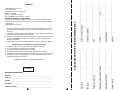
1
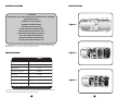
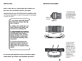
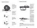
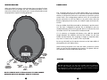
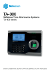
cut along dotted line SOUTHERN AUDIO SERVICES, INC. 15049 FLORIDA BLVD. BATON ROUGE, LA 70819 For: CS8A, EL8A, TA850 PLACE STAMP HERE 1008120401 CONGRATULATIONS CONTENTS Dear Friend, System Features . . . . . . . . . . . . . . . . . . . . . . . . . . . . . . . . . . . . .pg 3 Thank you for selecting Bazooka® subwoofer speaker systems for your car stereo system. Today, the Bazooka represents Bazooka Mobile Audio’s continued commitment to efficiency and design. An innovative manufacturing process developed by SAS for the Bazooka provides consumers with state-of-the-art speaker system design. At SAS, we take pride in manufacturing the most revolutionary bass speaker systems ever created, featuring our patented Bass Tubes® enclosure design, and we hope you will take pride in owning them. Specifications . . . . . . . . . . . . . . . . . . . . . . . . . . . . . . . . . . . . . . .pg 3 Location . . . . . . . . . . . . . . . . . . . . . . . . . . . . . . . . . . . . . . . . . . .pg 4 Mounting The Bazooka . . . . . . . . . . . . . . . . . . . . . . . . . . . . . .pg 5, 6, 7, 8 Wiring Diagram . . . . . . . . . . . . . . . . . . . . . . . . . . . . . . . . . . . . .pg 9 Power Wire . . . . . . . . . . . . . . . . . . . . . . . . . . . . . . . . . . . . . . . .pg 10 Ground Wire . . . . . . . . . . . . . . . . . . . . . . . . . . . . . . . . . . . . . . .pg 11 Remote Turn On Options . . . . . . . . . . . . . . . . . . . . . . . . . . . . .pg 11,12 Several years ago, we realized that efficiency was the wave of the future in autosound, so we made a commitment to design, manufacture, and deliver the most efficient speaker systems possible. Input Signal Connections . . . . . . . . . . . . . . . . . . . . . . . . . . . . .pg 13,14 Today we market our patented speaker systems worldwide and the high quality of the Bazooka brand is well respected by consumers and dealers of all nationalities. Warranty . . . . . . . . . . . . . . . . . . . . . . . . . . . . . . . . . . . . . . . . . .pg 16,17,18 Setting The Level . . . . . . . . . . . . . . . . . . . . . . . . . . . . . . . . . . . .pg 14 Practice Safe Listening . . . . . . . . . . . . . . . . . . . . . . . . . . . . . . .pg 15 When properly installed, Bazooka subwoofer speaker systems will give you years of clean uninterrupted sound reproduction. Therefore, I urge you to take a few minutes of your time to review this instruction booklet. It was designed to give you a better understanding of our products and to explain how to apply them properly. Thank you again for choosing Bazooka. Our early commitment to quality has made them the product of choice, and I am sure you will agree that you have made the right one! Enjoy! Sincerely, JON C. JORDAN President SAS/BAZOOKA 1 If you have any questions contact the SAS Technical Support Department at: Phone - (225) 272 7135 • Fax - (225) 272-9844 In Canada: (604) 988 2966 Email - [email protected] • Website - www.bazooka.com 14763 Florida Blvd., Baton Rouge, LA. 70819 2 SYSTEM FEATURES INSTALLATION 8” SUBWOOFER PATENTED BASS TUBES® ENCLOSURE WITH BASS REFLEX/DUCTED PORT ALIGNMENT* HIGH EFFICIENCY OUTPUT OPTIMIZED FOR SPACE EFFICIENCY DESIGNED FOR CORNER LOADING Figure 1 MOISTURE RESISTANT ENCLOSURE BUILT IN 50 WATT MAX AMPLIFIER POWER 18dB ELECTRONIC CROSSOVER FIXED @ 85 Hz. NOISE REJECTING BALANCED INPUT CIRCUITRY INPUTS ARE SUMMED MONO INTERNALLY SELECTABLE AUTOMATIC TURN ON FEATURE 12dB PER OCTAVE SUBSONIC FILTER @ 35 Hz. *BAZOOKA® subwoofer speaker systems exclusively incorporate the revolutionary Bass Tubes® patented subwoofer enclosure design available only from SAS.® SPECIFICATIONS Figure 2 TA850 Woofer Size Voice Coil Size 8 1 high power /high temp Magnet Size 15 oz. Frequency response 39-85 hz. Efficiency 105 dB* Dimensions 18.125x8.5x10 Weight 15.5 lbs. Impedance 2 ohms Figure 3 BASS TUBES® enclosure - patented Bass Reflex/ducted port alignment * The efficiency levels of all Bazooka subwoofer speaker systems are measured in the typical environment: In the low bass region with one watt of power. 3 4 INSTALLATION MOUNTING THE BAZOOKA Please take time to read through this manual and plan out your installation before you begin! Locate an area in the rear of the vehicle where you would like to place the Bazooka speaker system. The location you have selected must meet the following requirements in order for the Bazooka to be properly installed in the vehicle: 1) The woofer (grill end) should be facing into a corner. (See figures 1, 2 and 3) 1. With the top side of the buckle facing up (see figure 4), lace the strap through the mounting base as illustrated in figure 5. Top Logo should face up Figure 4 2) Ideally, there should be 2 to 4 inches between the woofer and the corner it is pointing into. 3) The mounting area should be carefully checked to be sure that the mounting screws will not damage the gas tank, electrical wiring, fuel lines, or the spare tire during the mounting of the strap bases. Figure 5 4) The strap mounting bases should be screwed securely to a rigid surface that is part of, or anchored to, the structure of the vehicle. 2. After the strap is completely laced through the mounting base, make a loop with the strap, where it runs across the middle of the base as illustrated in figure 6. This loop is necessary to access the two mounting holes in the base. Figure 6 Be sure that your application meets all of these requirements before you continue the installation procedure! 5 6 MOUNTING THE BAZOOKA MOUNTING THE BAZOOKA 3. Place each mounting base under the Bazooka so that the apex at the bottom of the tube sits inside the mounting base as in figure7. 7. Adjust buckle end of strap so that it extends out of the mounting base 22” (see figure 9) the proper length for the model size of Bazooka you are installing. 22” Figure 9 8. Remove any slack in the strap by feeding it out of the mounting base on the loose end of the strap opposite the buckle. 4. Move the bases so that they are spaced approximately 3” from each end of the enclosure as illustrated in figure 8. Figure 7 ,, 3 9. Place Bazooka on the mounting bases and fasten the buckles as illustrated in figure 10. The strap should loop through the buckle and be tightened securely by holding the strap in place with one hand and pulling the loose end away from the buckle, but against the cabinet. 5. Remove the Bazooka without moving the mounting bases and set it aside. Figure 10 6. Screw each mounting base securely in place with screws provided as illustrated in figure 6. ,, 3 Figure 8 7 Technical Note Due to the jarring and shifting that can occur in a vehicle, the mounting straps may stretch or loosen. We recommend that you check the straps regularly to assure that your Bazooka is mounted securely in place. 8 WIRING DIAGRAM POWER WIRE When using high level inputs, take the time after you make all wiring connections to run through the AM I IN PHASE procedure of this manual to confirm that your inputs are in correct electrical phase and the proper bass response is being produced. The 16 gauge red wire on the 14-pin Molex Mini-fit Jr. connector is the 12 Volt positive power wire. It must be fused and connected directly to the positive terminal of the battery to provide a power source with a low voltage drop and low noise. Do not make the power connection at the fuse block or any point other than the battery. Improper power sources can reduce output and cause distortion. The fuse holder should be connected to the battery's positive terminal. The fuse is designed to prevent fire or damage to your car, should the battery wire short to ground. Wait to insert the fuse into its holder until all wire connections have been made. If it is necessary to lengthen the battery wire, add the required length between the amplifier and the fuse holder, not the fuse holder and the battery. Use 16 gauge or larger to extend the battery wire. It is best to use as short a wire as possible. Be sure you DO NOT run the power wire next to the input cables of the amplifier, this will induce noise. Avoid running the power wire near the radio's antenna or power leads, or near sensitive equipment or harnesses. The power wire carries substantial currents and could induce noise. LEVEL 16 GAUGE BLACK CHASSI GROUND 16 GAUGE RED BATTERY (12v+) GRAY HI-LEV INPUT (+) QUICK DISCONNECT YELLOW ON/OFF JUMPER LOOP GRAY/TRACE HI-LEV INPUT (-) CAUTION ORANGE REMOTE GN/TRACE HI-LEV INPUT (-) GREEN HI-LEV INPUT (+) RCA PHONO PLUGS Right & Left Low Level Inputs DO NOT substitute the 7.5 amp fuse included with the Amplified Bazooka with anything other than the same fast blow current rated fuse. Substitution or deletion will void the product's warranty and may cause damage to your car or the amplifier. NOTE: REMOVE AUTO TURN-ON LOOP TO USE ORANGE REMOTE WIRE FOR NORMAL REMOTE TURN-ON 9 10 TURN ON OPTIONS CONT. GROUND WIRE The 16 gauge black wire on the 14-pin Molex Mini-fit Jr. connector is the negative ground wire. It must be connected directly to the vehicle chassis near the amplifier. We do not recommend extending the ground wire in any installation, as this can cause unwanted ground loops. The ground point in the car should be a piece of chassis metal that is part of or welded to the main body of the vehicle. Painted surfaces should be scraped or sanded clean to expose the bare metal before the ground lug is bolted down. (Cover the bare metal area with paint or grease after you finish mounting the ground wire to prevent rust.) REMOTE TURN ON OPTIONS The ORANGE wire on the Amplified Bazookas' 14-pin Molex Mini-fit Jr. connector is the Remote Turn On Wire. You have several options in connecting the Remote Turn On Wire. These options are listed in the order of preference recommended by SAS. Select the option best suited for your application. Option One: For the most versatility the Remote Turn On Wire should be connected to the source unit's "Accessory", "Auto-Antenna" or "Remote" lead -- any of which will supply 12 Volts positive when the source is turned on. When you are using this configuration, the Quick Disconnect YELLOW On/Off Jumper Loop MUST be disconnected from the wiring harness. 11 Option Two: If the source does not have an Auto-Antenna lead (or if the AutoAntenna goes down during tape operation),you can connect the Amplified Bazookas' Remote Turn On Wire to an accessory or ignition point at the vehicle fuse block. In this configuration, the Amplified Bazooka will be on whenever the ignition is on. This method may allow noise or turn-on-and-off transients to become amplified when the source unit is not in use. When you are using this Option, the Quick Disconnect YELLOW On/Off Jumper Loop MUST be disconnected from the wiring harness. Option Three: The Amplified Bazooka has a built -in Auto Turn-On Feature. If you choose to use this feature, the Amplified Bazooka will turn on automatically whenever there is music present at the inputs (high level or low level input). Please take notice of the Quick Disconnect Yellow On/Off Jumper Loop located on the Amplified Bazooka wiring harness. SAS ships the Amplified Bazooka with this Jumper Loop plugged into the wiring harness. When the JUMPER LOOP plugged in, the Auto Turn-On Option is in the ON position and the Amplified Bazooka will turn on automatically when it senses any music at the inputs. The ORANGE wire should not be connected to anything if this feature is being used. Be sure to insulate the end of the ORANGE wire so that it will not short to ground, as this may damage the Amplified Bazooka. 12 INPUT SIGNAL CONNECTIONS SIGNAL CONNECTIONS CONT. Should I Use High or Low Level Inputs? If the source unit has only speaker outputs, use the high-level inputs of the Amplified Bazooka. If the source unit has both high and low level outputs, we recommend using the high level inputs over the low level inputs, due to the configuration of the Amplified Bazooka's balanced input circuit. PLEASE NOTE THAT THE WIRING IN A FACTORY STEREO MAY NOT BE ELECTRICALLY IN PHASE EVEN WHEN YOU HAVE MADE THE PROPER CONNECTIONS. Take the time after you make your wire connections to run through the quick phase check procedure in the AM I IN PHASE? Section of this manual. NEVER USE BOTH high and lowlevel inputs at the same time! this situation, simply reverse the connections on ONE of the two input channels. When the wiring is in correct electrical phase, the level of bass output will be greatest when the balance control of the radio is set to the center position. High-Level Inputs: If the source unit has both front and rear speaker outputs, use only one set of speaker outputs for the high-level input of the Amplified Bazooka. Connect the GREEN wire from the 14-pin Molex plug of the Amplified Bazooka to the source units left (+) positive speaker output. Connect the GREEN W/BLACK stripe wire of the plug to the source units left (-) negative speaker output. Connect the GRAY wire of the plug to the source units right (+) positive speaker output. Connect the GRAY W/BLACK stripe wire of the plug to the source units right (-) negative speaker output. PHASE ALERT When one of the Amplified Bazooka's High-level Input channels is out of phase electrically with the other High-level Input channel, your Bazooka will sound as if it has little or no output and any output that is produced may sound distorted. If you suspect that your Bazooka is out of phase, use the AM I IN PHASE procedure to diagnose and correct the Bazookas' output, and proper bass response will be produced. LOW-LEVEL INPUT: If your source unit only has low-level RCA phono jack output, use only the low-level inputs of the Amplified Bazooka. Connect the low-level RCA phono jack inputs of the Amplified Bazooka to the source with a shielded RCA patch cord. To avoid possible noise problems, be sure to run the patch cord away from all power wires and factory wire harnesses. When using the low-level inputs DO NOT make any connections to the Green and Gray high-level input wires of the Amplified Bazooka and make sure these wires are insulated to avoid the possibility of a short circuit. SETTING THE LEVEL To set the level of the Amplified Bazooka, start with the control all the way to the left. The bass should be off or very low at this point. Turn up the head unit until the sound from the existing speakers starts to clip or distort. This should be the max volume point of the system. Now bring up the level of the Amplified Bazooka so that the bass volume blends well with the other speakers in the system. This should be the proper setting for the level control. Am I In Phase? If your inputs are out of phase and you turn the balance control of your radio all the way to one side, right or left, the bass output from the Bazooka will increase. When you bring the balance control back to the center position the bass level will drop. This confirms that one of your input channels is wired out of phase with the other. To correct 13 14 PRACTICE SAFE LISTENING LIMITED WARRANTY (UNITED STATES) Continuous exposure to high volumes of sound may cause permanent hearing loss. High powered auto sound systems are capable of producing sounds well over 130 dB. Even short periods of play at high volume levels can impair your ability to hear necessary traffic sounds and may constitute a hazard. Please use common sense and practice SAFE LISTENING! BASS TUBES® ENCLOSURE BAZOOKA® subwoofer speaker systems exclusively incorporate the revolutionary Bass Tubes® patented subwoofer enclosure design available only from SAS.® Southern Audio Services, Inc., warrants all products to be free from defects in material and workmanship for a period of one (1) year from the date of purchase; In the event the product is not as warranted, SAS sole obligation shall be to repair or replace the defective product at SAS option: SAS limits its obligation under any implied warranties under state laws to a period not to exceed the limited warranty period. SAS and its authorized BAZOOKA® dealers specifically disclaim liability for any incidental or consequential damages. Some states to not allow limitations on how long an implied warranty lasts, and some states do not allow the exclusion or limitation of incidental or consequential damages, so the above limitation or exclusions may not apply to you. This warranty gives you specific legal rights, and you may have other rights, which vary from state to state. What is covered: This warranty covers all defects in materials or workmanship (parts and labor) in the product. What is not covered: This warranty does not cover the following: 1. Damages occurring during shipment of the product to SAS for repair (claims must be presented to the carrier). 2. Damages caused by accident, abuse, negligence, misuse or improper operation or installation. 3. Damages caused by an act of God, including without limitation, fire, flood, storms, or other acts of nature. 4. Any product, which has a serial number, defaced, altered, modified, or removed. 5. Any product that has been altered or modified without SAS consent. SAS, Bazooka, Bass Tubes and “Listen to Your Ears” are registered trademarks of Southern Audio Services, Inc. © Southern Audio Services, Inc. all rights reserved 15 How to obtain warranty services: 1. You are responsible for delivery of the product to an authorized BAZOOKA® dealer or contact SAS at 1-800-THE TUBE for a Return Authorization number. The Return Authorization number must be clearly written on the outside of the box. Freight must be prepaid to SAS. Warranty replacement parts will be returned freight prepaid. The entire enclosure may be returned for warranty service, but return will be freight collect. 2. You must provide proof of the date of purchase of the product. If proof of purchase is not provided, original date of manufacture will be used to determine warranty period. 3. You must package the product securely to avoid damage during shipment. 4. After acquiring a Return Authorization number, ship to the address below. 16 Fecha de compra:_____________________________________________________________ 17 18 ____________________________________________ E-MAIL Producto:______________________________________________________________________ ____________________________________________ TELEPHONE Colonia ________________________________________________________________________ ____________________________________________ TELEPHONE Calle y #________________________________________________________________________ ____________________________________________ DEALER ADDRESS Nombre:________________________________________________________________________ ____________________________________________ STATE ZIP DATOS DEL DISTRIBUIDOR ____________________________________________ DEALER PURCHASED FROM Sello y firma De la tienda ____________________________________________ CITY GARANTIA VALIDA EN TU TIENDA DE SERVICIO ____________________________________________ PURCHASE DATE Esta garantía no es valida en los siguientes casos Cuando el producto no ha sido utilizado de acuerdo al instructivo. Si no se ha observado las advertencias señaladas Si ha sido expuesto a cambios bruscos de voltaje Si ha sufrido deterioro escencial irreparable atribuido al consumidor Cuando el producto ha sido alterado o reparado por personas jenas a nosotros Esta póliza es nula si no cuenta abajo con los datos requeridos y sellos de la tienda donde se realizó la compra. ____________________________________________ STREET ADDRESS 1.2.3.4.5.6.- ____________________________________________ SERIAL# 1.- Para hacer efectiva esta garantía, usted debe presentar la factura de compra o póliza debidamente llenada por la tienda o unidad vendedora junto con el producto. 2.- La empresa e compromete a reparar al producto, sin costo alguno al consumidor; si la falla es atribuible a defecto de fabricación. 3.- El tiempo de reparación en ningún caso será mayor de 30 días, transcurrido este término COIBA IMPORT S.A. DE C.V. procederá a Efectuar el cambio por un producto equivalente. 4.- Centro de Servicio:Torrecillas #2060 Guadalajara Jal. Col. El Rosario C.P. 44890 ____________________________________________ PURCHASERS NAME PLEASE RETURN THIS PORTION IMMEDIATELY COIBA IMPORT S.A. DE C.V Torrecillas # 2060 Guadalajara Jalisco Col. El Rosario México C.P. 44890 Modelo: CS8A, EL8A, TA850 RFC CIM-000901-1k0 Producto: Bocinas POLIZA DE GARANTIA CONDICIONES El producto que usted ha adquirido Cuenta con una garantía de 90 días Por defectos de fabricación y 90 días De servicio a partir de la fecha de Adquisición otorgada por: COIBA IMPORT S.A. DE C.V ____________________________________________ MODEL# IN MEXICO: