1
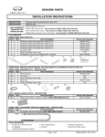
How to install the FAST-9999 with the FAST-BTAH: The FAST-9999 universal harness uses the patented Posi-Tap
connector from Posi-Products for making FAST secure connections to your OEM wire harness.
Modo de instalaci6n del FAST-9999 con el FAST-BTAH: El arnes universal FAST-9999 usa el conector patentado PosiTap de Posi-Products para hacer conexiones seguras de FAST a su arnes alambrico del fabricante del equipo original
(OEM) .
Co mment installer le FAST-9999 avec le FAST-BTAH: Le FAST-9999 est un harnais universe! qui s'installe avec le
connecteur brevete Posi-Tap, pour une installation securitaire avec les filages d'origine du vehicule.
Disconnect negative battery clamp from battery.
For easiest installation remove the radio and
disconnect the harness from the back of t he radio.
Desconecte Ia presilla de baterfa negativa de
Ia baterfa. Para facilitar aun mas Ia instalac ion,
remueva Ia radio y desconecte el arnes de atras de
Ia radio.
Deconnecter le pole negatif de Ia batterie. Pour
une installation plus facile, en lever Ia rad io et
deconnecter le harnais l'arriere du radio.
a
Red (+) 12V Power. Turns on when
ignition/accessory is on .
Blue/Wh ite Turns on remote
accessories (amplifiers, etc.) .
If there is no Remote Amplifier
wire, you can often use the power
an ten na wire.
White(+) Left Front Speaker
White/Black(-) Left Front Speaker
Gray(+) Right Front Speaker
Gra y/Black(-) Right Front Speaker
Con nect the Posi-Tap connectors
to t he corresponding wires of
your rad io harness. Consult
yo ur car or radio manufacturer's
m anual to get the correct color
codes fo r your vehicle.
Rojo (+) 12V de corriente. Se enciende
cuando se arranca el vehfculo o se enciende
el accesorio.
L'alimentation rouge(+) 12V fonctionne
quand l'accessoire est activee.
Le signal Bleu/Bianc active les accessoires
etc.). S'il n'y a pas
de signal (remote), vous pouvez ut iliser
le til d'alimentation d'antenne.
Azul/Blanco Enciende los accesorios
remotes (amplificadores, etcetera)
Si no hay alambre de Amplificador Remote,
en muchos cases puede usar el alambre de
Ia antena electrica.
a distance (amplificateur,
Blanco(+) Parlante delantero izquierdo
Blanco/Negro(-) Parlante delantero
izquierdo
Gris (+) Parlante delantero derecho
Gris/Negro (-) Parlante delantero derecho
Conecte los conectores Posi-Tap a los
alambres correspondientes de su arnes de
radio. Consulte el manual del fabricante
de su automovil o radio para obtener los
cod igos de color correctos para su vehfculo.
Blanc/Nair(-) Haut-parleur avant gauche
negatif
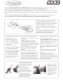
Remove the top cap. Place the
wire that is going to be tapped .
In the grove of the cap as far
down as it will go.
Remueva Ia tapa superior.
Coloque el alambre a ser
conectado en Ia ranura de Ia
tapa los mas profunda posible.
En lever le capuchon du
connecteur. Placer le til dans
Ia fente du capuchon le plus
profondement possible.
Blanc(+) Haut-parleur avant gauche positif
Gris (+) Haut-parleur avant droit positif
Gris/Noir (-) Haut-parleur avant droit
neg at if
Connecter Ia prise Posi-Tap au til
correspondant au harnais de votre radio.
Consulter le manuel du manufacturier de
votre radio ou de votre auto pour connaltre
les bons codes de couleur.
Make sure not to cross
thread the cap when
screwing it back in place.
Cerciorese de no forzar
Ia rosca con Ia tapa al
roscarla de nuevo.
a
Veiller ne pas croiser
le til dans le capuchon
en le vissant.
Continue to thread until
the cap is tight and the
wire is pierced .
Make sure to attach all 6
of the FAST-9999 harness
wires to your OEM harness.
Siga roscando hasta que
Ia tapa quede tensa y el
alambre perforado.
Siga roscando hasta que
Ia tapa quede ten say el
alambre perforado.
Continuer a Visser le
capuchon jusqu'a ce qu'il
soit bien serre et que le til
soit perce.
Attacher chacun des 6 fils
du harnais FAST-9999 a
votre harnais d'origine.
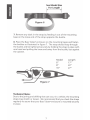
Make sure the end with the 6 pin Molex connectors is toward
the radio. Run the BTAH harness behind radio, dash and along
the edge of the vehicle until you get to the place you have
decided to mount the tube.
Cerci6rese de que el cabo de los conectores Molex de 6 espigas
quede orientado hacia Ia radio. Pase el arnes BTAH detras de Ia
radio, el tablero y por el borde del vehfculo hasta que alea nee
ellugar donde ha decidido montar el tuba.
Assurez-vous que l'extremite du connecteur Molex a 6 brins
so it bien fixee au radio. Passer le til du harnais BTAH derriere Ia
radio, le tableau de bard et le long du vehicule jusqu'a l'endroit
ou vous avez decide d'installer le tube.
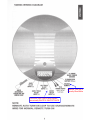
Plug the FAST-9999 harness into the FAST-BTAH. Mount
grounding ring and plug the 14 pin connector into the BASS
TUBE. For more information on placement and mounting, consult
your amplified tube instruction manual.
Conecte el arnes FAST-9999 en el FAST-BTAH. Monte el anillo
de conexi6n a tierra y conecte al conector de 14 espigas en el
TUBO DE BAJO. Para mayor informacion sabre Ia colocaci6n y
el montaje, consulte su manual de instrucciones para el tuba
amplificado.
Branchez le harnais FAST-9999 au FAST-BTAH. Fixer Ia mise a
Ia terre et installer le connecteur a 14 brins dans le Tube de
basse. Pour plus d'informations concernant !'emplacement
et !'installation, consulter le livre d'instructions de votre
amplificateur.
/
14-pin connector to the Bazooka
Conector de 14 espigas a Ia Bazooka
~
Ground to chassis of vehicle
Conectar a tierra en el chasis del vehicul
Connectez-vous
a terre sur le chassis vehicule
14-connecteur pin le Bazooka
Posi-Tap™ Patent# 5,228,875 5,695369 5,868,589 6,692,313 Jap 2881414, Aus 708700, Tia 103534,
Can 2204826 Mex 200626 Korea 477279, China Z1971 05562.9 & others pending.
Posi-Tap™ No. de Patente 5,228,875 5,695369 5,868.589 6.692,313 Jap 2881414, Aus 708700, Tia 103534,
Can 2204826 Mex 200626 Corea 477279, China Z1971 05562.9 y otros pendientes.
Posi-Tap TM Patent No. 5,228,875 5,695369 5,868.589 6.692,313 Jap 2881414, Aus 708700, Tia 103534,
Can 2204826. Mex 200626. Coree 477279. Chine et d'autres Z1971 05562.9 susoens.
~ •
MODELS • MODELE N° • MODELO: TA850C BTA850FH
Dear Friend,
Thank you for selecting Bazooka® subwoofer speaker systems for your
stereo system. Today, the Bazooka represents Bazooka Mobile Audio's
continued commitment to efficiency and design. An Jnnovative
manufacturing process developed by SAS® for the Bazooka provides
consumers with state-of-the-ar t speaker system design.
At SAS, we take pride in manufacturing the most revolutionary bass speaker
systems ever created, featuring our patented Bass Tubes® enclosure design,
and we hope you will take pride in owning them.
Several years ago, we realized that efficiency was the wave of the future
in Autosound, so we made a commitment to design, manufacture, and
deliver the most efficient speaker systems possible.
Today we market our patented speaker systems worldwide and the high
quality of the Bazooka brand is well respected by consumers and dealers
of all nationalities.
When properly installed, Bazooka subwoofer speaker systems will give
you years of clean uninterrupted sound reproduction. Therefore, I urge
you to take a few minutes of your time to review this instruction booklet.
It was designed to give you a better understanding of our products and
to explain how to apply them properly.
Thank you again for choosing Bazookas. Our early commitment to quality
has made them the product of choice, and I am sure you will agree that
you have made the right one! Enjoy!
Sincerely,
JON C. JORDAN
President
SAS/BAZOOKA
1
CONTENTS
HELPFUL HINTS BEFORE YOU BEGIN
PG3
VEHICLE PLACEMENT RECOMMENDATIONS
PG4
MOUNTING THE BAZOOKA
PG 5-7
WIRING DIAGRAM
PG8
SPECIFICATIONS
PG9
WIRING
PG 10-12
TROUBLESHOOTING
PG 13-14
WARRANTY
PG 15-16
2
HELPFUL HINTS-BEFORE YOU BEGIN
Please take time to read through this manual and plan out your
installation before you begin!
Locate an area in the rear of the vehicle where you would like to place
the Bazooka speaker systems. The location you have selected must
meet the following requirements in order for the Bazooka to be properly
installed in the vehicle:
1) The woofer (grill end) should be facing into a corner. (See
vehicle placement recommendations on p_g. 5-6)
2) Ideally, there should be 2 to 4 inches between the woofer and
the corner it is pointing into.
3) The mounting area should be carefully checked to be sure
that the mounting screws will not damage the gas tank,
electrical wiring, fuel lines, or the spare tire during the mounting
of the strap bases.
4) The strap mounting bases should be screwed securely to a
rigid surface that is part of, or anchored to, the structure of
the vehicle.
3
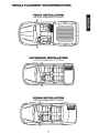
VEHICLE PLACEMENT RECOMMENDATIONS
TRUCK INSTALLATION
tube size is exaggerated for emphasis
HATCHBACK INSTALLATION
tube size is exaggerated for emphasis
SEDAN INSTALLATION
tube size is exaggerated for emphasis
4
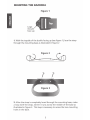
MOUNTING THE BAZOOKA
Figure 1
Logo
should
face up
1. With the topside of the buckle facing up (see figure 1), lace the strap
through the mounting base as illustrated in figure 2
c[tY__.~~F-ig-ure--.2·- ~
r r
I
I
2. After the strap is completely laced through the mounting base, make
a loop with the strap, where it runs across the middle of the base as
illustrated in figure 3. This loop is necessary to access the two mounting
holes in the base.
5
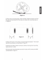
Figure 4
3. Place each mounting base under the Bass Tubes® enclosure so that
the apex at the bottom of the tube sits inside the mounting base as
in figure 4.
I
I
I
/
~--------------
---------,
I
I
I
I -- ,
- - - - - - - - - - - - - - - - - - - - - - - - - --{ I '
I
'
1
,,
I
I
I
I
I
I
I
I
I
I
I
I
I
I
\.
.......
-
-
-
-
-
- -
-
-
-
-
-
-
-
-
- - - - - - - -
-
~...
I
I
- ,_,
Figure 5
4. Move the bases so that they are spaced approximately 3" from each
end of the enclosure as illustrated in figure 5.
5. Remove the Bass Tubes® enclosure without moving the mounting
bases and set it aside.
6. Screw each mounting base securely in place with screws provided
as illustrated in figure 3.
6
See Model Size
I·
For Length
·I
1. Remove any slack in the strap by feeding it out of the mounting
base on the loose end of the strap opposite the buckle.
8. Place the Bass Tubes® enclosure on the mounting bases and fasten
the buckles as illustrated in figure 7. The strap should loop through
the buckle and be tightened securely by holding the strap in place with
one hand and pulling the loose end away from the buckle, but against
the cabinet.
Model
6"
8"
10"
Length
17"
22"
27"
Figure 7
Technical Note:
Due to the jarring and shifting that can occur in a vehicle, the mounting
straps may stretch or loosen. We recommend that you check the straps
regularly to assure that your Bass Tubes® enclosure is mounted securely
in place.
7
TABSOC WIRING DIAGRAM
16 GAUGE
BLACK CHASSIS
GROUND
16 GAUGE RED
BAnERY (12¥+)
QUICK
DISCONNECT
YELLOW ON/OFF
JUMPER LOOP
ORANGE
GN/TRACE
REMOTE
RCA
HI·LEY
PHONO PLUGS
INPUT(-)
Remote Turn-On is
Right & left low
GREEN
GRAY/TRACE
level
Inputs
Actually Blue/White
HI·LEV
HI·LEV
INPUT(-)
INPUT(+)
The GN & GN/TRACE wires shown
are actually WHITE & WHITE/TRACE
NOTE:
REMOVE AUTO TURN-ON LOOP TO USE ORANGE REMOTE
WIRE FOR NORMAL REMOTE TURN-ON
8
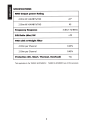
SPECIFICATIONS
RMS Output power Rating
4 Ohm@ 14.4V@1 %THO
22*
2 Ohm@ 14.4V@1%THD
45
3 dB 21 Hz-85Hz
Frequency Response
SIN Ratio (dba) 1W
>70
THD with A-Weight filter
4 Ohm per Channel
0.23o/o
2 Ohm per Channel
0.43o/o
Protection (DC, Short, Thermal, Overload)
*Not applicable to the TA850C & BTA850FH
9
Yes
TA850C & BTA850FH are 2 Ohm products
DO NOT substitute the fuse included with the Amplified Bazooka
subwoofer with anything other than the SAME fast blow current
rated fuse. Substitution or deletion will void the product•s warranty
and may cause damage to your car or the amplifier.
SHOULD I USE HIGH OR LOW LEVEL INPUTS?
If the source unit has only speaker outputs, use the high-level inputs
of the Amplified Bazooka subwoofer. If the source unit has both high
and low level outputs, we recommend using the high level inputs
over the low level inputs, due to the configuration of the Amplified
Bazooka subwoofer•s balanced input circuit. Not all head units, even
those that promise high output voltage in their marketing materials,
indeed have high-voltage RCA outputs. Because of this, Bazooka
Mobile Audio recommends using the speaker level inputs when in
doubt-they will always provide sufficient drive level to the amplifier.
PLEASE NOTE THAT THE WIRING IN A FACTORY STEREO MAY NOT BE
ELECTRICALLY IN PHASE EVEN WHEN YOU HAVE MADE THE PROPER
CONNECTIONS.
Take the time after you make your wire connections to run through
the quick phase check procedure in the "AM I IN PHASE?" section at
the end of this manual, and NEVER USE BOTH high and low-level
inputs at the same time!
INPUT SIGNAL CONNECTIONS
High-Level Inputs:
If the source unit has both front and rear speaker outputs, use
only one set of speaker outputs for the high-level input of the
Amplified Bazooka. Connect the GREEN wire from the 14-pin
Molex plug of the Amplified Bazooka subwoofer to the source
units left(+) positive speaker output. Connect the GREEN W/BLACK
stripe wire of the plug to the source units left(-) negative speaker
output. Connect the GRAY wire of the plug to the source units
right(+) positive speaker output. Connect the GRAY W/BLACK
stripe wire of the plug to the source units right(-) negative speaker
output. When using high-level inputs, take the time after you
make all wiring connections to run through the AM I IN PHASE
procedure at the end of this manual to confirm that your inputs
are in correct electrical phase and the proper bass response is
being produced.
10
Low-Level Inputs:
If your source unit only has low-level RCA phono jack output, use only
the low-level inputs of the Amplified Bazooka. Connect the low-level
RCA phono jack inputs of the Amplified Bazooka subwoofer to the
source with a shielded RCA patch cord. To avoid possible noise
problems, be sure to run the patch cord away from all power wires
and factory wire harnesses. When using the low-level inputs DO NOT
make any connections to the Green and Gray high-level input wires
of the Amplified Bazooka subwoofer and make sure these wires are
insulated to avoid the possibility of a short circuit.
POWER WIRE
The power wire must be fused and connected directly to the positive
terminal of the battery to provide a power source with a low voltage
drop and low noise. Do not make the power connection at the fuse
block or any point other than the battery. Improper power sources
can reduce output and cause distortion.
The fuse holder should be connected to the battery•s positive terminal.
The fuse is designed to prevent fire or damage to your car, should
the battery wire short to ground. Wait to insert the fuse into its holder
until all wire connections have been made.
If it is necessary to lengthen the battery wire, add the required length
between the amplifier and the fuse holder, not the fuse holder and
the battery. If you need to extend t he battery wire, use 16 gauge
or larger for all A 100, and 12 gauge or larger for all A200 models. It
is best to use as short a wire as possible. Be sure you DO NOT run the
power wire next to the input cables of the amplifier this will induce
noise. Avoid running the power wire near the radio•s antenna or
power leads, or near sensitive equipment or harnesses. The power
wire carries substantial currents and could induce noise.
GROUND WIRE
The ground wire must be connected directly to the vehicle chassis
near the amplifier. We do not recommend extending the ground wire
in any installation, as this can cause unwanted ground loops.
The ground point in the car should be a piece of chassis metal that
is part of or welded to the main body of the vehicle. Painted surfaces
should be scraped or sanded clean to expose the bare metal before
the ground lug is bolted down. (Cover the bare metal area with paint
or grease after you finish mounting the ground wire to prevent rust.)
11
REMOTE TURN ON OPTIONS
OPTION ONE:
When you are using this option with all amplified Bass Tubes®
models: For the most versatility the Orange Remote Turn On Wire
should be connected to the source unit•s .. Accessory .. , .. Auto-Antenna ..
or .. Remote .. lead-- any of which will supply 12 Volts positive when
the source is turned on.
OPTION TWO:
When you are using this option
If the source does not have an Auto-Antenna lead {or if the AutoAntenna goes down during tape operation), you can connect the
Amplified Bazookas· Remote Turn On Wire to an accessory or ignition
point at the vehicle fuse block. In this configuration, the Amplified
Bazooka subwoofer will be on whenever the ignition is on. This
method may allow noise or turn-on-and-off transients to become
amplified when the source unit is not in use, and therefore is a less
desirable than option one. Locate the Auto/Off Jumper Loop located
on the wiring harness; SAS ships the Amplified Bazooka subwoofer
with this Jumper in the ON Position. The Quick Disconnect YELLOW
On/Off Jumper Loop must be plugged into the harness.
12
TROUBLESHOOTING
Am I In Phase?
If your inputs are out of phase and you turn the balance
control of your radio all the way to one side, right or left, the
bass output from the Bazooka® will increase. When you bring
the balance control back to the center position the bass level
will drop. This confirms that one of your input channels is
wired out of phase with the other.
When one of the Amplified Bazooka·s High-level Input channels
is out of phase electrically with the other High-level Input
channel, your Bazooka will sound as if it has little or no output
and any output that is produced may sound distorted. If you
suspect that your Bazooka is out of phase, use the AM I IN
PHASE procedure to diagnose and correct the Bazookas· output,
and proper bass response will be produced. channels is wired
out of phase with the other. To correct this situation, simply
flip the phase switch on the amplified Bazooka®. When the
input signal is in correct electrical phase, the level of bass
output will be greatest when the balance control of the radio
is set to the center position.
Do You Have A Phase Problem?
If the bass response in your application appears to be lower
then you expected or sounds muffled and or distorted, you
may be experiencing Phase Cancellation.
Phase Cancellation
When two speakers in the same frequency range produce
sound waves that are inverted from one another or 180° out
of phase, the sound waves will cancel each other out to some
degree. This effect will be heard as a drop in the output level
and/or a muffled or muddy quality in the Bass Response. The
source of this Phase Cancellation can be at any point in the
signal path. The obvious cause of this problem would be a
speaker connection that was reversed in polarity, but that is
not always the case. Sometimes amplifier channels will shift
phase 180° for no good reason, or a signal processor could
have a setting for phase that has been set incorrectly or the
13
source material could just be recorded in error. Also speaker
placement and the acoustics of the listening environment can
effect the phase. No matter what or where the cause is located,
the solution is an easy one.
PHASE CORRECTING PROCEDURE
Disconnect all but one Bazooka® from your system. Be sure
that any loose wire connections are insulated to avoid the
chance of short-circuiting any of the electronic equipment.
Listen to the system and take note of the level of the Bass
Response. Connect the next Bazooka® and compare the level
of the combined output to that of the single unit. If the Bass
Response increases, the Phasing is correct and you can repeat
this process on the next Bazooka. If the level of the Bass
Response drops, the Phasing is incorrect and you should reverse
the speaker connections to this Bazooka® and compare again.
In short to INCREASE IS GOOD, to DECREASE IS BAD! Using
this method, any number of Bazooka® subwoofers can be kept
in absolute phase.
PRACTICE SAFE LISTENING
Continuous exposure to high volumes of sound may cause
permanent hearing loss. High-powered auto sound systems
are capable of producing sounds well over 130 dB. Even short
periods of play at high volume levels can impair your ability
to hear necessary traffic sounds and may constitute a hazard.
Please use common sense and practice SAFE LISTENING!
14
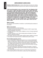
LIMITED WARRANTY (UNITED STATES)
Southern Audio Services, Inc., warrants all products to be free from defects
in material and workmanship for a period of one (1) year from the date of purchase.
In the event the produd is not as warranted, SAS' sole obligation shall
be to repair or replace the defedive produd at SAS' option: SAS limits
its obligation under any implied warranties under state laws to a period
not to exceed the limited warranty period. SAS and its authorized
BAZOOKA® dealers specifically disclaim liability for any incidental or
consequential damages. Some states to not allow limitations on how
long an implied warranty lasts, and some states do not allow the exclusion
or limitation of incidental or consequential damages, so the above
limitation or exclusions may not apply to you. This warranty gives you
specific legal rights, and you may have other rights, which vary from
state to state.
What is covered:
This warranty covers all defects in materials or workmanship (parts and labor) in
the product.
What is not covered:
This warranty does not cover the following:
1. Damages occurring during shipment of the product to SAS for repair (claims
must be presented to the carrier).
2. Damages caused by accident, abuse, negligence, misuse or improper operation
or installation.
3. Damages caused by an act of God, including without limitation, fire, flood,
storms, or other acts of nature.
4. Any product, which has a serial number, defaced, altered, modified, or removed.
5. Any product that has been altered or modified without SAS' consent.
How to obtain warranty services:
1. You are responsible for delivery of the product to an authorized BAZOOKA®
dealer or contact SAS at 1-800-THE TUBE for a Return Authorization number.
The Return Authorization number must be clearly written on the outside of the
box. Freight must be prepaid to SAS. Warranty replacement parts will be
returned freight prepaid. The entire enclosure may be returned for warranty
service, but return will be freight collect.
2. You must provide proof of the date of purchase of the product. If proof of
purchase is not provided, original date of manufacture will be used to determine
warranty period.
3. You must package the product securely to avoid damage during shipment.
4. After acquiring a Return Authorization number, ship to the address below.
15
PLEASE RETURN THIS PORTION IMMEDIATELY
MODEL#
SERIAL#
PURCHASE DATE
DEALER PURCHASED FROM
DEALER ADDRESS
TELEPHONE
PURCHASERS NAME
STREET ADDRESS
CITY
STATE
ZIP
TELEPHONE
E-MAIL
16