1
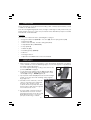
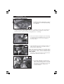
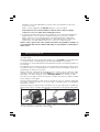
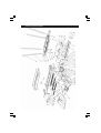
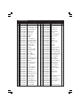
600W ELECTRIC TILE CUTTER
MODEL No: ETC400
Part No: 3400748
OPERATION & MAINTENANCE
INSTRUCTIONS
0706
SPECIFICATIONS
Motor: .......................................................................... 230v ~ 50Hz 1ph
Power Rating: ............................................................................... 600W
No Load Speed: .................................................................... 3000 RPM
Operating Temperature: ............................................... -15°C to 40°C
Fuse Rating: .............................................................................. 13 amp
Table Dimensions: ........................................................... 500 x 385mm
Cutting Angle: ............................................................................ 0° - 45°
Max Cutting Depth @ 90°: ......................................................... 25mm
Max Cutting Depth @ 45°: ......................................................... 17mm
Cutting Disk: ..................................................... Ø180 x Ø22.2 x 2.2mm
Sound Power Level: .......................................................... 84.2 dB Lwa
Sound Pressure Level: ......................................................... 71.2 dB (A)
Vibration Emissions: ................................................................. <2.5m/s²
Overall Dimensions (LxWxH): ............................... 760 x 590 x 930mm
Net Weight: .................................................................................... 27Kg
Duty Cycle: ...................................................................................... S1**
** May be run continuously
Please note that the details and specifications contained herein, are correct at the time of going to print. However,
CLARKE International reserve the right to change specifications at any time without prior notice.
Waste electrical products should not be disposed of with general household waste. Please dispose
of at your local recycling facility.
-2-
Thank you for purchasing this CLARKE Tile Cutter designed for DIY and light commercial use
for cutting all types of ceramic tiles..
Before attempting to use the cutter, please read this manual thoroughly and follow the
instructions carefully. In doing so you will ensure the safety of yourself and that of others around
you, and you can look forward to the equipment giving you long and satisfactory service.
CLARKE GUARANTEE
This CLARKE product is guaranteed against faulty manufacture for a period of 12
months from the date of purchase. Please keep your receipt as proof of purchase.
This guarantee is invalid if the product is found to have been abused or tampered
with in any way, or not used for the purpose for which it was intended.
Faulty goods should be returned to their place of purchase, no product can be
returned to us without prior permission.
This guarantee does not effect your statutory rights.
CONTENTS
Page No
Specifications ........................................................................................ 2
Declaration of Conformity .................................................................. 2
Guarantee ............................................................................................. 3
Safety Precautions ................................................................................ 4
Electrical Connections ......................................................................... 5
Check List ............................................................................................... 6
Assembly ................................................................................................ 7
Operation .............................................................................................. 8
Maintenance ........................................................................................ 9
Parts Diagram ...................................................................................... 10
Parts List ................................................................................................ 11
NOTE: this instruction manual is not a definitive guide to tiling, but a guide on using this
equipment only.
-3-
SAFETY PRECAUTIONS
WARNING:
As with all machinery, there are certain hazards involved with their operation
and use. Exercising respect and caution will considerably lessen the risk of
personal injury. However, if normal safety precautions are overlooked or
ignored, personal injury to the operator or damage to property, may result.
1.
ALWAYS Learn the machines applications, limitations and the
specific potential hazards peculiar to it. Read and become familiar
with the entire operating manual.
2.
ALWAYS use a face or dust mask if operation is particularly dusty.
3.
ALWAYS check for damage. Before using the machine, any
damaged part, should be checked to ensure that it will operate
properly, and perform its intended function. Check for alignment of
moving parts, breakage of parts, mountings, and any other
condition that may affect the machines operation. Any damage should be
properly repaired or the part replaced. If in doubt, DO NOT use the machine.
Consult your local dealer.
4.
ALWAYS disconnect the tool/machine from the power supply before servicing and
when changing accessories.
5.
ALWAYS wear safety goggles, manufactured to the latest European Safety
Standards. Everyday eyeglasses do not have impact
resistant lenses, they are not safety glasses.
6.
ALWAYS keep work area clean. Cluttered areas and
benches invite accidents.
7.
ALWAYS ensure that adequate lighting is available. A
minimum intensity of 300 lux should be provided. Ensure
that lighting is placed so that you will not be working in
your own shadow.
8.
ALWAYS keep children away. All visitors should be kept a safe distance from the
work area, especially whilst operating the machine.
9.
ALWAYS maintain machine in top condition. Keep tools/ machines
clean for the best and safest performance. Follow maintenance
instructions.
10.
ALWAYS handle with extreme care do not carry the tool/
machine by its’ electric cable, or yank the cable to disconnect
it from the power supply.
11.
ALWAYS ensure the switch is off before plugging in to mains. Avoid
accidental starting.
12.
ALWAYS concentrate on the job in hand, no matter how trivial it may
seem. Be aware that accidents are caused by c
carelessness due to familiarity.
13.
ALWAYS keep your proper footing and balance at all
times - don’t overreach. For best footing, wear rubber
soled footwear. Keep floor clear of oil, scrap wood, etc.
14.
ALWAYS keep your hands well away from the cutting disk.
-4-
ELECTRICAL CONNECTIONS
Connect the mains lead to a standard, 230 Volt (50Hz) electrical supply
through an approved 13 amp BS 1363 plug, or a suitably fused isolator
switch.
WARNING! THIS APPLIANCE MUST BE EARTHED
IMPORTANT: The wires in the mains lead are coloured in accordance
with the following code:
Green & Yellow
-
Earth
Blue
-
Neutral
Brown
-
Live
As the colours of the flexible lead of this appliance may not correspond
with the coloured markings identifying terminals in your plug proceed as
follows:
•
Connect the GREEN & YELLOW cord to terminal marked with a letter
“E” or Earth symbol “ ” or coloured GREEN or GREEN & YELLOW.
•
Connect BROWN cord to terminal marked with “L” or coloured RED.
•
Connect BLUE cord to the terminal marked with “N” or coloured BLACK.
If this appliance is fitted with a plug which is moulded onto the electric
cable (i.e. non-rewirable) please note:
1. The plug must be thrown away if it is cut from the electric cable. There is a
danger of electric shock if it is subsequently inserted into a socket outlet.
2. Never use the plug without the fuse cover fitted.
3. Should you wish to replace a detachable fuse carrier, ensure that the
correct replacement is used (as indicated by marking or colour code).
4. Replacement fuse covers can be obtained from your local dealer
or most electrical stockists.
Fuse Rating
The fuse in the plug must be replaced with one of the same rating - 13amps
and this replacement must be ASTA approved to BS1362.
Cable Extension
If a cable extension is needed, it is essential to ensure that the size of the
conductors is at least the same size as those of the power cable supplied.
-5-
CHECK LIST
Before attempting to assemble and use the tiling cutter, carefully unpack and lay out the
contents on a clean surface.
Check for missing/damaged parts. If any shortages or damage is found, please notify your
Clarke dealer where the cutter was purchased ASAP, alternatively telephone Clarke
International on 020-8988-7400.
CONTENTS
Note: Item Nos in brackets refer to parts diagram on page 9
•
4 x legs with rubber feet (75 & 74) + 4 x Screws (80), and 4 x Spring washers (79).
•
1 x Base frame (77).
•
1 x Main cutter assembly, includes cutting disk (fitted).
•
1 x Adjustable Guide ( 1 & 45 to 54)
•
2 x Stop (1, 2 & 3).
•
1 x Water tray (73).
•
2 x Retaining Clamp (28 & 76).
•
2 x Wrench.
•
1 x Hexagon Wrench.
•
1 x Operation and Maintenance Instruction Manual.
ASSEMBLY
1. Attach the legs to the base unit using the screws and washers supplied, do not tighten
screws until all four screws are fitted finger tight, once the four legs are loosely fitted rest
the stand on a firm flat surface.
Fig. 1
Proceed to tighten all the leg securing screws with hex key
provided, DO NOT overtighten.
2. Loosely attach the retaining clamps (76) with bolts (81)
inserted from inside the base and securing knobs on the
outside (28) as in fig. 1, DO NOT tighten yet.
3. Lay the plastic water tank (73) into the base unit ensuring it
sits flat, secure in position with retaining clamps, tighten
finger tight only.
4. Carefully rest the main body of the tile
cutter on the edge of the water tank
as in Fig. 2 (also see Fig. 3 pump
location). Ensure the pump with cable
and hose are routed down through the
hole in the base as shown.
5. Hook the edge of the pump into the
side bracket as shown at ‘A’ whilst
pivoting the pump as shown at ‘B’, and
finally pressing home to secure the
pump as shown in Fig 3 overleaf.
-6-
Fig. 2
ASSEMBLY cont.
6. Install the pump by clipping into position
as shown in Fig. 3, ensure the pump tubing
is not kinked.
Fig. 3
7. Once the pump is clipped firmly into position, carefully lower the cutter assembly into
position in the water tank taking care not to trap the pump tubing or pump power
lead. Check the cutter assembly is sitting flat before continuing.
Fig. 4
8. Remove the head securing knob, arrowed in Fig.
4, This will free the head and allow it to be moved
in order to gain access to the securing post,
arrowed in Fig. 5.
Fig. 5
9. Unscrew and remove the securing post and, store
safely, with securing nut, for use if the cutter is
transported at a later date.
NOTE: removing the securing post is optional, and is
only necessary in order to use the maximum table
width available.
Carefully continue traversing the head towards
the R/H side until it reaches the stop.
Fig. 6
10. To prevent damage to the electrical
input cable and the coolant hose, they
are encased in a flexible track. The track
needs to be secured at the motor end
as indicated in Fig.6, using the two
screws provided
-7-
Fig. 7
11. Two Head Transverse Stops are provided on
the top of the machine. These allow head
movement to be restricted, as desired.
Thread the slides on to the screw threads
of the transverse stops, ensurintg they are
the right way up, then screw on the stop
knobs as shown in Fig.7 Fig. 7
Temporarily position stops, one at each
end of the unit and loosely secure with
locking knobs.
12. Screw the plug into the hole in the water tank, ensuring the
rubber washer is beneath the tank.
13. Finally, remove the cutting disk cover - three screws, and check
to ensure the disk is properly secured. Remember the securing
nut carries a LEFT HAND THREAD - turn ANTICLOCKWISE to
TIGHTEN.
OPERATION
CAUTION: Ensure the unit is completely stable by adjusting the legs accordingly
1. Fill the water tank with clean cold water until the top of the pump is just covered, DO
NOT overfill. Check the water level constantly during use and top up as necessary.
L/H Side
Fig. 8
R/H Side
2. Traverse the head as far as possible to the
left hand side of the machine.
3. With the machine disconnected from the
mains supply, measure the tile to be cut and
proceed to adjust:
a.) The angle of the cutting head which
can be adjusted up to 45 degrees from
the horizontal for mitre edge cuts if
required. For normal straight cuts at 90°,
the head should be set to zero degrees
in the scale at the R/H end of the
machine.
Fig. 9
b.) For straight cuts, remove the Mitre Gauge by
unscrewing the two knurled nuts arrowed in Fig. 9 and slide
the assembly out of the housing. The tile is then place up
against the fence as desired.
For angle cutting, the mitre gauge is set as indicated in
Fig.9, with the appropriate angle set, and the gauge fully
locked in position.
5. Start the machine by pressing the green button on the switch
panel, marked ‘I’, wait for the cutting disc to reach full speed
before continuing.
6. Hold the tile to be cut firmly at all times, against the gauge/
fence. Slowly move the head towards the R/H side until
the cutting disc just touches the tile. Continue steadily
moving the head whilst observing the cut as you do so.
-8-
DO NOT force the head. Maintain the maximum disc speed at all times, allow the
tool to do the work.
Always cut in a straight line and DO NOT attempt to cut a curved line.
Keep hands well clear of the disk whilst it is in motion. Remove all pieces using a
scrap piece of wood, or similar, before making the next cut.
5. To stop the machine at any time, press the red button on the switch panel marked ‘O’.
NEVER attempt to slow the machine quickly by putting excess pressure on the disk.
Always do this as soon as cutting has been completed, and before making any
adjustments to the machine. NEVER attempt to make adjustments, however small,
whilst the disc is running, ALWAYS wait for it to come to a complete stop first.
NOTE: In order to get the feel of the machine and reduce the possibility of wastage, we
recommend that trial cuts are made first with surplus or scrap material of a similar type to
that to be cut.
MAINTENANCE
When carrying out servicing or maintenance tasks...ALWAYS disconnect the machine from
the mains supply.
Clean external parts of the machine with a damp soft cloth, DO NOT use harmful abrasives
or chemicals as this could damage the machine and invalidate your warranty
The bearings etc are all sealed and packed with lubricant which should last the lifetime of
the machine.
Periodically inspect for wear, the runners on the underside of the aluminium extrusion (Item
6 in parts list) which the head bearings run, clean the runners and reapply a thin film of
general purpose grease to the runners.
Always rotate the cutting disk by hand before use to check for cracks or distortion. If any
damage is detected, renew the disk. NEVER use a cracked/damaged cutting disc.
Remember - the disk securing nut carries a LEFT HAND THREAD. Turn clockwise to undo.
Check the power cable to ensure it is in perfect condition, any defects should be rectified
before using the cutter again.
Drain the water tank after use and ensure it is dry before storing. To clean the water tank
thoroughly, it will be necessary to remove the tank completely (refer to the installation
instructions to do this).
Clean the pump by running it under cold water to remove any sediment etc. Separate the
filter from the body by carefully turning the filter housing half a turn and gently pulling apart,
taking care not to let the Impeller etc fall out.
ALWAYS maintain the machine in top condition. When not in use, keep it covered, and
store in a dry place, not exposed to the elements.
-9-
PARTS DIAGRAM
-10-
PARTS LIST
No. Part No
Description
1
2
3
4
5
6
7
8
9
10
11
12
13
14
15
16
17
18
19
20
21
22
23
24
25
26
27
28
29
30
31
32
33
34
35
36
37
38
39
40
41
Knob
Locating Block (A)
Locating Block (B)
Hex Bolt M6x20
Guide Ruler
Guide Bar
Wing Nut
Flange
Baffle
Screw M5x12
Spring Washer Ø5
Flat Washer Ø5
Inner Blade Cover
Rubber Stop
Screw M5x16
Clamp
Flat Washer Ø8
Ecentric Shaft
Bearing
Circlip Ø9
Motor Bracket
Pointer
Spring Washer Ø8
Hex Bolt M8x12
Handle
Hex Bolt M6x16
Screw M5x20
Knob
Locking Knob
Hex Bolt M6x18
Side Bracket
Hex Post
Chain Assembly
Outer Blade Cover
Hex Nut M8
Outer Flange
Cutting Disc
Screw M6x16
Spring Washer Ø6
Inner Flange
Hex Nut M8
HTETC40001
HTETC40002
HTETC40003
HTETC40004
HTETC40005
HTETC40006
HTETC40007
HTETC40008
HTETC40009
HTETC40010
HTETC40011
HTETC40012
HTETC40013
HTETC40014
HTETC40015
HTETC40016
HTETC40017
HTETC40018
HTETC40019
HTETC40020
HTETC40021
HTETC40022
HTETC40023
HTETC40024
HTETC40025
HTETC40026
HTETC40027
HTETC40028
HTETC40029
HTETC40030
HTETC40031
HTETC40032
HTETC40033
HTETC40034
HTETC40035
HTETC40036
HTETC40037
HTETC40038
HTETC40039
HTETC40040
HTETC40041
Qty No. Part No
2
2
2
2
1
1
2
1
1
2
2
2
1
2
2
2
4
1
2
4
1
1
4
2
1
4
4
2
2
3
1
1
1
1
1
1
1
1
1
1
4
42
43
44
45
46
47
48
49
50
51
52
53
54
55
56
57
58
59
60
61
62
63
64
65
66
67
68
69
70
71
72
73
74
75
76
77
79
80
81
82
83
-11-
HTETC40042
HTETC40043
HTETC40044
HTETC40045
HTETC40046
HTETC40047
HTETC40048
HTETC40049
HTETC40050
HTETC40051
HTETC40052
HTETC40053
HTETC40054
HTETC40055
HTETC40056
HTETC40057
HTETC40058
HTETC40059
HTETC40060
HTETC40061
HTETC40062
HTETC40063
HTETC40064
HTETC40065
HTETC40066
HTETC40067
HTETC40068
HTETC40069
HTETC40070
HTETC40071
HTETC40072
HTETC40073
HTETC40074
HTETC40075
HTETC40076
HTETC40077
HTETC40079
HTETC40080
HTETC40081
HTETC40082
HTETC40083
Description
Screw M6x16
Motor
Power Cord
Slide Block
Mitre Gauge
Pointer
Flat Washer Ø4
Screw M4x6
Nut
Washer
Washer
Mitre Gauge
Knob
Pointer
Washer
Side Bracket (B)
Bracket (A)
Extension Table (B)
Front Rail (Right)
Large Washer, Ø5
Hex Bolt M5x25
Screw M4x10
Main Table
Front Rail Left
Extension Table (A)
Table Support
Hex Nut M6
Large Washer
Bracket (B)
Hex Bolt M6x40
Pump
Water Tank
Rubber Foot
Leg
Retaining Clamp
Base frame
Spring Washer
Skt Screw M10x20
Square Bolt
Hose
Water Tank Plug
Qty
2
1
1
2
1
1
1
1
1
1
1
1
1
1
1
1
1
1
1
1
2
8
1
1
1
2
4
4
1
4
1
1
4
4
2
1
4
4
2
1
1