1
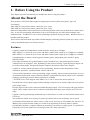
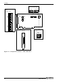
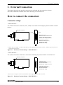
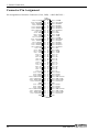
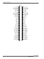
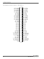
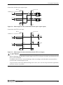
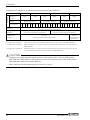
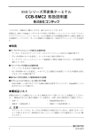
2. Setup
Step 2 Setting the Hardware
This section describes how to set this product and plug it on your PC.
This product has some switches and jumper to be preset.
Check the on-product switches and jumpers before plugging this product into an expansion slot.
This product can be set up even with the factory defaults untouched. You can change this product
settings later.
Parts of this product and Factory Defaults
Figure 2.1. - 2.2. shows the names of major parts on this product.
Note that the switch setting shown below is the factory default.
- Synchronization signal
connector (CN2, CN3)
- Terminator setting
SW
(SW2 - SW5)
1 2 3 4 5 6 7 8
SW1
BOARD ID
SW4
SW5
- Board ID setting
switch
- Interface connector
(CNA, CNB)
CNB
CNA
456
SW1
BOARD ID
789
23
1 2 3 4 5 6 7 8
1 2 3 4 5 6 7 8
SW3
1 2 3 4 5 6 7 8
ON
SW3
ON
SW4
ON
CN3
BCDE
SW5
CN2
A
ON
SW2
CN3
F01
SW2
CN2
Figure 2.1. Component Locations < SMC-8DF-PCI >
SMC-4DF-PCI, SMC-8DF-PCI
13