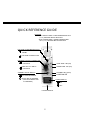
1
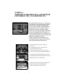
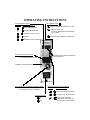
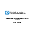
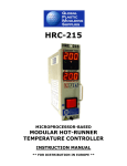
IMP PIM
Zone Temperature
Controller
for Runnerless Molding
Applications
Manual
SAM
ATHENA...
TEMPERATURE/PROCESS AND POWER
CONTROLS YOU CAN DEPEND ON.
Since 1965, Athena Controls, Inc. has been at
the forefront of control technology, and was
one of the first companies to offer a fully
microprocessor-based, 1/4 DIN digital temperature controller. Our product line has
expanded to include a complete range of
panel, rack-mounted, and open-card process
controllers, highly efficient SCR power controllers and solid-state motor contactors, and
specialized temperature control products and
systems for the plastics industry.
Athena’s products are sold and serviced
worldwide through a network of authorized
sales representatives and distributors.
• General Purpose Microprocessor and Analog
Controllers
• SPI-Compatible 1/32, 1/16, 1/8, and 1/4 DIN
Auto-Tune Process Controllers
• Ramp-Soak and Multi-Input Process Controllers
• Low-Cost, Non-Indicating Temperature Controllers
• Phase Angle and Zero Switched SCR Power Controls
• Phase Angle and Zero Switched Solid-State Contactors
• Staging Controllers for Large KW Loads
• Single and Multi-Zone Hot Runner Control Modules
• Portable Controller and Mainframe Systems
• Cables, Mounting Boxes, and Accessories
2
OPERATING INSTRUCTIONS
ALARM/MODE DISPLAY
DISPLAY
ALARM SYMBOLS
DOT INDICATORS
POWER BEING DELIVERED TO LOAD
OVER TEMPERATURE
THERMOCOUPLE OPEN
MANUAL MODE ON
(DISPLAY INDICATES PERCENTAGE
OF POWER)
NO HEAT
REMOTE AND STANDBY OPERATION
UNDER TEMPERATURE
THERMOCOUPLE REVERSED
DIGITAL SETPOINT SWITCH
ACCURATELY SETS A
SETPOINT TEMPERATURE
TEMPERATURE AND PERCENTAGE
POWER DISPLAY
STANDBY (WARM) REGION
PERCENTAGE POWER ADJUSTMENT KNOB
CONTROLS PERCENTAGE OF POWER
SUPPLIED TO LOAD IN MANUAL
POWER SWITCH
ON
OFF
MODE SELECT TOGGLE SWITCH
DISPLAY
MODE SYMBOLS
OPEN LOOP (MANUAL MODE)
CLOSED LOOP (AUTO MODE)
COMPUSTEP START-UP
ON DURING FIVE MINUTE
COMPUSTEP TIME PERIOD
PIM SERIES
PORTABLE SINGLE ZONE
HORIZONTAL CONTROLLER
ALARM/DISPLAY
DISPLAY
ALARM SYMBOLS
OVER TEMPERATURE
UNDER TEMPERATURE
DIGITAL SETPOINT SWITCH
ACCURATELY SETS A
SETPOINT TEMPERATURE
THERMOCOUPLE OPEN
NO HEAT
THERMOCOUPLE REVERSED
STANDBY (WARM) REGION
TEMPERATURE AND PERCENTAGE
POWER DISPLAY
POWER SWITCH
ON
OFF
MODE SELECT TOGGLE SWITCH
DISPLAY
MODE SYMBOLS
DOT INDICATORS
OPEN LOOP (MANUAL MODE)
POWER BEING DELIVERED TO LOAD
CLOSED LOOP (AUTO MODE)
MANUAL MODE ON
(DISPLAY INDICATES PERCENTAGE OF POWER)
COMPUSTEP START-UP
ON DURING FIVE MINUTE
COMPUSTEMP TIME PERIOD
PERCENTAGE POWER ADJUSTMENT KNOB
CONTROLS PERCENTAGE OF POWER
SUPPLIED TO LOAD IN MANUAL
4
OPERATING INSTRUCTIONS
IMP Series 15 and 30 Amp Temperature Controllers
PIM Series 10 and 15 Amp Temperature Controllers
Section I. General Description
The IMP and PIM Series are microprocessor based PID controllers
specifically designed to perform most operator functions
automatically. The IMP Series are plug-in units, while the PIM
Series are portable, stand-alone instruments. Both are
self-adjusting and capable of maintaining a very high degree of
temperature accuracy over a wide range of operating conditions.
A digital display eliminates parallax error caused by conventional
analog methods of display. This enhances the accuracy of the
controller while making information easier to see.
Simplified controls and the use of status symbols allow the
operator to make adjustments easily. The status display also
provides visual indication of normal or abnormal operating
conditions in both controller and load.
All that is required of the operator is to set the temperature
desired. From that point on, the controller will automatically
perform all the operations required to achieve and maintain the
selected temperature.
Included in the design is a built-in safety feature which when
operating in closed-loop mode will automatically cut off the
controller output power when any TC fault is detected. In openloop operation, the display shows percentage of power as set by
the power control potentiometer (0-100%).
5
The IMP plug-in controller is capable of receiving a standby
command from the SAM auxiliary module. When a standby or low
heat command is acknowledged from the SAM during closedloop operation, the controller will operate with a fixed setpoint.
When receiving a standby command during open-loop operation,
the output power of the controller will be reduced to 1/4 of the
front panel power control setting.
The IMP controller also sends alarm status conditions to
the SAM auxiliary module for annunciation and remote
control functions.
Section II. Installation (IMP Series Only)
All IMP Series controllers are ready to use as shipped from the
factory. Prior to installation into a mainframe, make sure the
voltage, Hz and degree options are as ordered and correspond to
the Product ID label.
CAUTION
Never insert or remove a controller from a mainframe
with the AC power on. Hazardous potentials exist on
components inside the mainframe and controller.
Always disconnect AC power to the mainframe when
servicing.
6
To install a plug-in controller into a mainframe, release the
locking device on the lower edge of the unit by pulling the plunger
gently away from the panel. Align the upper and lower edges of
the printed circuit board on the controller with the mainframe
card guide slot and slide in until the rear connector is completely
engaged. Lock the controller into the frame by depressing the
plunger on the locking device.
Section III. Operation
Note: Any flashing display indicates that a fault has been detected
by the controller. Refer to section on Faults.
A.
Automatic Closed-loop Operation
1- Position Mode select switch to closed-loop (“o”).
2- Set temperature on Setpoint switch.
3- Turn on AC power.
4- After a short reset delay, the measured temperature will
be displayed. If the temperature is 30 degrees F (17°C) or
more below setpoint, the undertemperature alarm
display (lower segment of the leftmost digit) will flash. If
the temperature is 30 degrees F (17°C) or more above
setpoint, the overtemperature alarm display (upper
segment of the leftmost digit) will flash. During alarm
conditions, temperature display will also flash. If the
temperature is within alarm limits, the display will stop
flashing, and the leftmost digit will display closed-loop
mode (“o”).
5- Power to load indicator (the decimal point of the
leftmost digit) will be on if any power is being
applied to the load.
7
6-
B.
When any of the thermocouple (TC) faults are detected,
output power will be cut-off automatically and the
temperature display will be blanked out. The leftmost
digit will show “ ” for (TC open), “ ” for (TC reverse)
or “ ”for No Heat and flash twice per second.
Automatic Operation with CompuStep ® system
When starting from cold, it is recommended that the
CompuStep system be used, as this will serve to lengthen
heater life considerably.
1- Position the mode select switch to CompuStep mode
(“ ”).
2- Set the desired temperature on the setpoint switch.
3- Turn on the AC power.
4- After reset delay, the measured temperature will be
displayed. If temperature is less than 200 degrees F
(93°C) the controller will enter the CompuStep mode.
This is indicated by the step symbol “ ” on the leftmost
digit. During this mode, the controller gradually
increases power to load in small steps and limits the
load temperature to 256 degrees F (124°C). After 5
minutes, the controller will exit from CompuStep mode
and automatically go to setpoint. Any thermocouple
faults detected during the 5 minute interval will cause
the CompuStep mode to end prematurely. A standby
command from a SAM module will also terminate
CompuStep mode. When CompuStep ends, the
controller will operate as described in the Automatic
Closed-Loop Operation section. If temperature is above
200 degrees F (93°C), controller will bypass CompuStep
and go directly to setpoint.
8
C. Manual Open-Loop Operation
1- Position the mode select switch to open-loop (“ ”).
2- Turn the AC power on.
3- After reset delay, the controller will display the percentage of output power as adjusted by the power control
knob. The percentage power indicator will be on. Thus
0.00 corresponds to 0% (no power) and 1.00
corresponds to 100% (full power). The leftmost digit will
display open-loop mode ( “ ” ). 75% power is shown
as 0.75.
D. Manual Control Pre-Set
The following procedure can be used to pre-set the Manual power
control knob position in the event of a thermocouple break in
closed-loop operation.
A good thermocouple is required to start with, as this procedure
compares the temperature attained using automatic (closed-loop)
control with that obtained using manual (open-loop) control.
When the temperature is the same using either automatic or
manual control, then the position of the Manual power control
knob is correct.
9
Procedure for Manual Control Pre-Set
1- Adjust controller for closed-loop operation and obtain
good molded parts. This will adjust the controller to the
proper temperature.
2- Position the module select switch to open-loop and set
the manual control knob to roughly 25%. Wait for 10
seconds, than momentarily switch to closed-loop mode
to examine the temperature. If it is above the setpoint,
the manual power is too high to maintain proper
temperature. If it is below setpoint, the manual power
is too low. Adjust the power control knob accordingly,
wait for 10 seconds, then re-examine the temperature
by switching momentarily to closed-loop mode. Repeat
this procedure until the temperature is the same in
either automatic or manual control.
E. Standby Heat (SAM module only)
Standby heat is a low heat level used to keep heaters and
associated equipment warm. Its purpose is to prevent moisture
build-up in heaters and equipment during idle periods and to
provide fast start-up when returning to normal operations.
When using a Standby Alarm Module (SAM), activate the standby
switch. The SAM will send a standby command to all controllers.
A controller, upon receiving the command, will respond accordingly to its present mode of operation:
a- If the controller is in closed-loop mode, the setpoint becomes 200 degrees F (93°C) regardless of
the setpoint switch setting. The Remote Standby
Indicator (the decimal of the last digit) will be
10
on, indicating that the remote standby function
is active.
b- If the controller is in open-loop mode, the power
output is reduced to 1/4 of the value adjusted by
the power control knob. Notice that the % power
display will show the reduced value. The remote
standby indicator will be on.
F.
1-
2-
Faults
Overtemperature alarm:
A constant overtemperature alarm is most likely caused
by a shorted triac in the controller or incorrect or
shorted mold wiring. Switch module power off as
quickly as possible and replace controller or correct
wiring error. Check for thermocouple or heater cross
wiring.
Undertemperature alarm:
Undertemperature alarm is normal during system
start- up before the setpoint is reached. If under
temperature persists, a No Heat fault will occur.
11
3-
4-
Thermocouple open or reversed:
If any TC fault is detected during closed-loop operation,
the output power will be cut off. If it is necessary to
apply power to the load during a TC fault condition,
the controller can be switched to manualmode. The
output power will be a function of the manual control
knob setting. Since the controller is now operating in
open-loop mode, extreme care must be taken when
adjusting to prevent excess output power which would
overheat the load.
No heat fault:
The IMP series controller has included in its
microprocessor a program which detects that the
temperature is not rising as it should in response to full
power output. “No Heat” is defined as the condition
under which the temperature does not increase more
than 2 degrees F during a 60-second interval during
start-up. It takes 60 seconds to detect “No Heat” when
power is first turned on in closed-loop mode, and longer
if CompuStep is active.
In the beginning of the CompuStep mode, only a small
amount of power is applied to the load and the rate of
temperature rise could be less than 2 degrees F (1°C) in
60 seconds. In order to compensate for this, the test is
not performed until one minute after power is turned
on. By that time, enough power is being applied to the
load to sustain the rate of 2 degrees F (1°C) in 60 seconds. It takes 1 minute, 60 seconds to detect “No
Heat” in CompuStep mode when power is first turned
on. When “No Heat” alarm is detected, output power is
cut off.
12
What to do:
A. Try resetting the controller by turning its AC power OFF and
then ON.
B. If “No Heat” persists, then the problem could be one of the
following.
a- Open heater or load.
b- Thermocouple shorted. Switch to manual mode to
override this condition.
c- Load circuit open. This can be caused by an open power
cable, an open connector or a failed triac in the
controller. Exchange the module with a known good
module to eliminate suspect triac or module.
d- Slow heater. Use higher power heater or operate in
manual mode until setpoint is achieved.
e- Thermocouple too far away from heat source which
causes less than 2 degrees F (1°C) rise in 60 seconds due
to thermal lag. Move thermocouple as close to heater as
possible or use heater with built in thermocouple.
f- To defeat “No Heat” circuit, if not used or required,
remove jumper J4 and that circuit will no longer be
active.
User’s Selected Jumper Option
1- For degree Celsius operation,
install jumper on PC board marked J1
2- For 50 Hz operation
install jumper on PC board marked J2
Since the microprocessor reads the status of the jumpers during
power up, the power has to be turned off and on again in order to
activate the jumper function.
13
34-
For 120 Vac input operation,
install the 2 jumpers on the PC board as shown.
For 240 Vac input operation,
install the 1 jumper on the PC board as shown.
Note:
prior to installing a
14
OPERATING INSTRUCTIONS
Model SAM Communications Module
Section I. Installation
CAUTION
Never insert or remove the module from a main frame
with the AC power on. Always switch the module
or main frame to “off.” Hazardous potentials exist on
components inside both the module and main frame.
Always disconnect the AC power to the main frame
when servicing.
SAM must be used in conjunction with a model ”MFC“
communications-type main frame, and one or more IMP type
microprocessor-based temperature controllers. It is shipped from
the factory ready to use. No special preparation is required.
Installation Procedure:
1.1 Carefully unpack module. SAM may be plugged into any
unused zone of the main frame.*
1.2 Release locking device by gently pulling push-pull fastener
away from the front panel.
1.3 Line up module printed circuit board with respective main
frame guides. Insert module firmly, making sure rear
connectors are fully engaged.
1.4 Lock module into place by depressing push-pull fastener.
*Note: SAM will work in any main frame zone. A heater connected to
a zone with a SAM inserted will not affect operation of the module.
15
Section II. General Specifications
Standby Temperature
200 deg F (93 deg C)
AC Input Requirements
240 Vac +10% -20%, 48-63 Hz
(standard)120 Vac (Available)
Alarm Limits
+/- 30 deg F (17 deg C) when used
with an IMP
Alarm Output (Audible)
Over Temperature: 2 KHz tone at
2 Hz interval
Under Temperature: 1 KHz tone at
1Hz interval
Alarm Output (Visual)
Over Temperature: 2 Hz flashing
rate
Under Temperature: 1 Hz flashing
rate
Output Connector
AMP MIL-style connector (4 Pin)
providing Normally Closed and
Normally Opened relay contacts.
(5 amps maximum)
Communication Capacity
50 zones maximum
16
QUICK REFERENCE GUIDE
SPEAKER
FAST HIGHER TONE = OVER TEMPERATURE 30°F
(17°C) OR MORE ABOVE SETPOINT
SLOW LOWER TONE = UNDER TEMPERATURE
30°F (17°C) OR MORE BELOW SETPOINT
LOW TEMP ALARM MODE SWITCH
LOW TEMP ALARM MODE
INHIBIT
LOW TEMP ALARM ACTIVE
EXTERNAL OUTPUT CONNECTOR
PINS 1&2 - N.C. RELAY
CONTACTS
OVER TEMP. LED (red)
UNDER TEMP. LED (red)
PINS 1&3 - N.O. RELAY
CONTACTS
STANDBY LED (yellow)
STANDBY ON-OFF SWITCH
POWER ON LED
DAY USE OR NORMAL
NIGHT USE OR STANDBY
(YELLOW STANDBY LED
ILLUMINATES)
POWER SWITCH
ON
OFF
LOCKING DEVICE
17
Section III. Basic Operation
3.1
3.2
3.2.1.
3.2.2.
3.3.
3.4.
Select Normal or Standby Mode.
Select Low Temperature Alarm Mode.
Low Temperature Alarm Inhibit : Speaker will
be off and output relay inactive in the event of
low temperature condition (useful during start-up
procedures).
Low Temperature Alarm Active
: 30°F (17°C) or
more below IMP setpoint temperature will sound
alarm and energize output relay contacts.
Turn Power On-Off Switch to ”ON“ position.
Alarm indications are automatic.
(see detailed operation)
Section IV. Detailed Operation
4.1 Normal or Standby Operation
a. Normal : In this mode the standby feature is
defeated and temperature control is in accordance
with the IMP controller(s) settings.
b. Standby : With the toggle switch in this position,
the standby mode is engaged. This will set the temperature of all IMP controllers operating in automatic
mode to a standby temperature of 200 deg F (93 deg C).
(1) Any IMP controller operating in manual mode will
have its output power level reduced to 1/4 of its
present level.
(2) When SAM and IMP controller(s) are in use at nor mal operating temperature [setpoint above 230 deg
F (119 deg C )], switching to standby mode will result
in an over temperature alarm until all zones cool
down to below 230 deg F (110 deg C).
18
4.2 Alarm Indications: When an overtemperature or
undertemperature condition exists in any zone occupied by
an IMP controller, both audio (tones) and visual (LED)
alarms will occur in the SAM.
a. Over Temp. : Occurs when an IMP thermocouple is 30
deg F (17 deg C) or more above setpoint. The speaker will
emit a higher pitched audio tone of about 2 KHz repeating
about twice per second. At the same time, the over temper ature LED will flash, and relay closure will occur.
b. Under Temp. : Occurs when an IMP-15 thermocouple is
30 deg F (17 deg C) or more below setpoint. The speaker
will emit a lower pitched audio tone of about 1 KHz repeating about once per second. At the same time, the undertemperature LED will flash, and relay closure will occur.
c. Over Temp. Alarm Priority: If an overtemperature and
undertemperature condition exist simultaneously from
more than one IMP controller, SAM will indicate only the
overtemperature condition. SAM will not recognize any
undertemperature condition, until all overtemperature
alarms have been cleared.
4.3 Front Panel Output Connector: A set of relay contacts are
available at this connector for use with external equipment if
desired. Observe the 5 amp maximum contact rating. Pins 1
and 2 have normally closed (N.C.) contacts. Pins 1 and 3 have
normally opened (N.O.) contacts.
a. During either an over-or under-temperature alarm condition, the relay will be energized.
b. Relay operation is defeated when the Low Temperature
Alarm mode switch is in the Inhibit ( ) position. (This will
be clarified in the next section.)
19
4.4 Low Temperature Alarm Mode Switch: This switch gives the
operator the ability to defeat both the low temperature audio
alarm, and output connector relay operation. This feature is
useful to avoid sounding an alarm during startup or cooling
down procedures. The undertemperature LED is unaffected
by this switch. All overtemperature alarm indications are also
unaffected by this switch.
a. Low Temp. Alarm Active
: In this position, undertemperature alarm indications operate normally.
b. Low Temp. Alarm Inhibit
: In this position, an undertemperature condition of 30 deg F (17 deg C) or more
below setpoint will not sound the audio alarm. Also, the
output connector relay will not be energized. The undertemperature LED is unaffected, and will flash as usual.
4.5 Remote Standby Option: It is possible to wire the main frame
for remote standby operation as outlined in the following
procedure.
a. Locate the appropriate communications connector for the
zone to be occupied by the SAM. This is on the upper strip
of connectors on the rear of the model “MFC” main frame.
b. Carefully wire an isolated set of normally open relay
contacts, rated at 5 volts and1/2 amp, to pins 8 and 12
of the main frame connector. Note that this relay is
not included.
c. When the remote relay is energized, SAM will be placed in
the standby mode of operation.
d. A SAM must be installed for this option to work.
20
NOTES
21
MOLD
(FEMALE)
(MALE)
v
CABLE END
CKPTM1
v
CABLE END
CKPTF1
CABLE
MPTC10 (10 FOOT)
MPTC20 (20 FOOT)
MAINFRAME CONNECTOR
CKPTOC1
MOLD CONNECTOR
CKPTIC1
POWER OUT
AND
THERMOCOUPLE
PIM1B15
NEMA IN,
5 PIN OUT
CKPTM1
PIM1A15
NEMA IN,
NEMA OUT
POWER
IN
AC2024F
OUTPUT
AC INPUT
OUTPUT
FEMALE
PLUG
22
THERMOCOUPLE
INPUT
POWER
OUT
THERMO COUPLE
AC1524M
M2MJ
AC INPUT
MALE
PLUG
MALE
PLUG
PIM1A10
POWER CORD IN,
5 PIN OUT
AC INPUT
OUTPUT
23