1
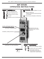
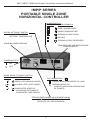
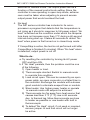
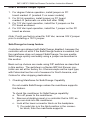
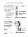
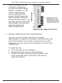
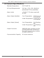
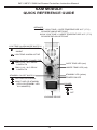
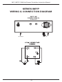
SERIES
IMP IMP/P SAM
HOT RUNNER CONTROLLERS
Instruction
Manual
Two-Year Limited Warranty
THIS EQUIPMENT IS WARRANTED TO BE FREE FROM DEFECTS OF MATERIAL
AND WORKMANSHIP. IT IS SOLD SUBJECT TO OUR MUTUAL AGREEMENT THAT THE
LIABILITY OF THE MANUFACTURER IS TO REPLACE OR REPAIR THIS EQUIPMENT
AT ITS FACTORY, PROVIDED THAT IT IS RETURNED WITH TRANSPORTATION PREPAID WITHIN TWO (2) YEARS OF ITS PURCHASE.
THE PURCHASER AGREES THAT THE MANUFACTURER ASSUMES NO LIABILITY
UNDER ANY CIRCUMSTANCES FOR CONSEQUENTIAL DAMAGES RESULTING
FROM ITS USE OR FROM IMPROPER HANDLING OR PACKAGING OF SHIPMENTS
RETURNED TO THE FACTORY.
COMPONENTS WHICH WEAR OR WHICH ARE DAMAGED BY MISUSE ARE NOT
WARRANTED. THESE INCLUDE CONTACT POINTS, FUSES, ELECTROMECHANICAL
RELAYS, AND TRIACS. UNITS WHICH HAVE BEEN MODIFIED BY A CUSTOMER IN
ANY WAY ARE NOT WARRANTED.
Other than those expressly stated herein, THERE ARE NO OTHER WARRANTIES
OF ANY KIND, EXPRESS OR IMPLIED, AND SPECIFICALLY EXCLUDED BUT NOT
BY WAY OF LIMITATION, ARE THE IMPLIED WARRANTIES OF FITNESS FOR A
PARTICULAR PURPOSE AND MERCHANTABILITY.
IT IS UNDERSTOOD AND AGREED THE SELLER’S LIABILITY WHETHER IN
CONTRACT, IN TORT, UNDER ANY WARRANTY, IN NEGLIGENCE OR OTHERWISE
SHALL NOT EXCEED THE RETURN OF THE AMOUNT OF THE PURCHASE PRICE
PAID BY THE PURCHASER AND UNDER NO CIRCUMSTANCES SHALL SELLER BE
LIABLE FOR SPECIAL, INDIRECT, INCIDENTAL OR CONSEQUENTIAL DAMAGES.
THE PRICE STATED FOR THE EQUIPMENT IS A CONSIDERATION IN LIMITING
SELLER’S LIABILITY. NO ACTION, REGARDLESS OF FORM, ARISING OUT OF THE
TRANSACTIONS OF THIS AGREEMENT MAY BE BROUGHT BY PURCHASER MORE
THAN ONE YEAR AFTER THE CAUSE OF ACTION HAS ACCRUED.
SELLER’S MAXIMUM LIABILITY SHALL NOT EXCEED AND BUYER’S REMEDY IS
LIMITED TO EITHER (i) REPAIR OR REPLACEMENT OF THE DEFECTIVE PART OR
PRODUCT, OR AT SELLER’S OPTION (ii) RETURN OF THE PRODUCT AND REFUND
OF THE PURCHASE PRICE, AND SUCH REMEDY SHALL BE BUYER’S ENTIRE AND
EXCLUSIVE REMEDY. THE SPECIFICATIONS PUT FORTH IN THIS MANUAL ARE
SUBJECT TO CHANGE WITHOUT NOTICE.
Athena Controls, Inc.
5145 Campus Drive
Plymouth Meeting, PA 19462
Phone: 610-828-2490
Fax: 610-828-7084
www.athenacontrols.com
You can reach our technical support team by phoning 1-800-782-6776 (from the United
States) or 610-828-2490 (from anywhere in the world). The e-mail address for tech support
is [email protected].
Athena® is a registered trademark of Athena Controls, Inc.
© 2003 Athena Controls, Inc. All rights reserved.
IMP I IMP/P I SAM Hot Runner Controllers Instruction Manual
Table of Contents
Section 1
1.1
1.2
1.3
Section 2
2.1
2.2
2.3
2.4
IMP I IMP/P Series
General Description...................................... 3
Installation (IMP Series Only)....................... 4
Operation...................................................... 4
Model SAM
Communications Module
Installation....................................................
General Specifications..................................
Basic Operation............................................
Detailed Operation........................................
CompuStep™ and SafeChange™ are trademarks of Athena Controls, Inc.
12
13
15
15
IMP I IMP/P I SAM Hot Runner Controllers Instruction Manual
IMP SERIES
OPERATING INSTRUCTIONS
ALARM/MODE DISPLAY
DISPLAY
ALARM SYMBOLS
DOT INDICATORS
POWER BEING DELIVERED TO LOAD
OVER TEMPERATURE
THERMOCOUPLE OPEN
MANUAL MODE ON
(DISPLAY INDICATES PERCENTAGE
OF POWER)
NO HEAT
REMOTE AND STANDBY OPERATION
%
UNDER TEMPERATURE
THERMOCOUPLE REVERSED
DIGITAL SETPOINT SWITCH
ACCURATELY SETS A
SETPOINT TEMPERATURE
TEMPERATURE AND
PERCENTAGE POWER
DISPLAY
STANDBY (WARM) REGION
PERCENTAGE POWER ADJUSTMENT KNOB
CONTROLS PERCENTAGE OF POWER
SUPPLIED TO LOAD IN MANUAL
MODE SELECT TOGGLE SWITCH
DISPLAY
MODE SYMBOLS
OPEN LOOP (MANUAL MODE)
POWER SWITCH
COMPUSTEP START-UP
ON DURING FIVE MINUTE
COMPUSTEP TIME PERIOD
ON
0
CLOSED LOOP (AUTO MODE)
OFF
1
IMP I IMP/P I SAM Hot Runner Controllers Instruction Manual
IMP/P SERIES
PORTABLE SINGLE ZONE
HORIZONTAL CONTROLLER
ALARM/DISPLAY
DISPLAY
ALARM SYMBOLS
OVER TEMPERATURE
UNDER TEMPERATURE
DIGITAL SETPOINT SWITCH
ACCURATELY SETS A
SETPOINT TEMPERATURE
THERMOCOUPLE OPEN
NO HEAT
THERMOCOUPLE REVERSED
STANDBY (WARM) REGION
TEMPERATURE AND PERCENTAGE
POWER DISPLAY
POWER SWITCH
ON
0
OFF
MODE SELECT TOGGLE SWITCH
DISPLAY
MODE SYMBOLS
DOT INDICATORS
OPEN LOOP (MANUAL MODE)
POWER BEING DELIVERED TO LOAD
CLOSED LOOP (AUTO MODE)
%
COMPUSTEP START-UP
ON DURING FIVE MINUTE
COMPUSTEP TIME PERIOD
MANUAL MODE ON
(DISPLAY INDICATES PERCENTAGE
OF POWER)
PERCENTAGE POWER ADJUSTMENT KNOB
CONTROLS PERCENTAGE OF POWER
SUPPLIED TO LOAD IN MANUAL
2
IMP I IMP/P I SAM Hot Runner Controllers Instruction Manual
SECTION 1
OPERATING INSTRUCTIONS
IMP Series 15 and 30 Amp Temperature Controllers
IMP/P Series 10 and 15 Amp Temperature Controllers
1.1 General Description
The IMP and IMP/P Series are microprocessor-based PID
controllers specifically designed to perform most operator
functions automatically. The IMP Series are plug-in units,
while the IMP/P Series are portable, stand-alone instruments.
Both are self-adjusting and capable of maintaining a very
high degree of temperature accuracy over a wide range of
operating conditions.
Simplified controls and the use of status symbols allow the
operator to make adjustments easily. The status display also
provides visual indication of normal or abnormal operating
conditions in both controller and load.
All that is required of the operator is to set the temperature
desired. From that point on, the controller will automatically
perform all the operations required to achieve and maintain
the selected temperature.
Included in the design is a built-in safety feature that will
automatically interrupt the controller output power when any
thermocouple (T/C) fault is detected, when operating in
closed-loop mode. In open-loop operation, the display
shows percentage of power as set by the power control
potentiometer (0-100%).
The IMP plug-in controller is capable of receiving a standby
command from the Standby Alarm Module (SAM) auxiliary
module. When a standby or low heat command is acknowledged from the SAM during closed-loop operation, the
controller will operate with a fixed setpoint. When receiving a
standby command during open-loop operation, the output
power of the controller will be reduced to 1/4 of the front panel
power control setting.
3
IMP I IMP/P I SAM Hot Runner Controllers Instruction Manual
The IMP controller also sends alarm status conditions to the SAM
auxiliary module for annunciation and remote control
functions.
1.2 Installation (IMP Series Only)
All IMP Series controllers are ready to use as shipped from
the factory. Prior to installation into a mainframe, make sure the
voltage, Hz, and degree options are as ordered and correspond to
the Product ID label.
CAUTION
Never insert or remove a controller from a mainframe
with the AC power on. Hazardous potentials exist on
components inside the mainframe and controller. Always
disconnect AC power to the mainframe when servicing.
To install a plug-in controller into a mainframe, release the
locking device on the lower edge of the unit by pulling the
plunger gently away from the panel. Align the upper and lower
edges of the printed circuit board on the controller with the
mainframe card guide slot and slide in until the rear connector
is completely engaged. Lock the controller into the frame by
depressing the plunger on the locking device.
1.3 Operation
Note: Any flashing display indicates that the controller has
detected a fault. Refer to section on Faults.
Automatic Closed-Loop Operation
1. Position Mode select switch to closed-loop (“O”).
2. Set temperature on Setpoint switch.
3. Turn on AC power.
4. After a short reset delay, the measured temperature will be
displayed. If the temperature is 30 ºF (17 °C) or more
below setpoint, the under temperature alarm display (lower
segment of the leftmost digit) will flash. If the temperature
4
IMP I IMP/P I SAM Hot Runner Controllers Instruction Manual
is 30 ºF (17 °C) or more above setpoint, the over
temperature alarm display (upper segment of the leftmost
digit) will flash. During alarm conditions, temperature display
will also flash. If the temperature is within alarm limits, the
display will stop flashing, and the leftmost digit will display
closed-loop mode (“ ”).
5. Power to load indicator (the decimal point of the leftmost digit)
will be on if any power is being applied to the load.
6. When any of the T/C faults are detected, output power will be
cut off automatically and the temperature display will be
blanked out. The leftmost digit will show “ ” for (T/C open),
“ ” for (T/C reverse) or “ ” for No Heat and flash twice per
second.
Automatic Operation with CompuStep system
When starting from cold, it is recommended that the CompuStep
system be used to lengthen heater life considerably.
1.
2.
3.
4.
Position the mode select switch to CompuStep mode (“ ”).
Set the desired temperature on the setpoint switch.
Turn on the AC power.
After reset delay, the measured temperature will be displayed.
If temperature is less than 200 ºF (93°C) the controller will
enter the CompuStep mode. This is indicated by the step
symbol “ ” on the leftmost digit. During this mode, the
controller gradually increases power to load in small steps.
After 5 minutes or when the temperature reaches 256 ºF
(124 °C), the controller will exit from CompuStep mode and
automatically go to setpoint. Any thermocouple faults detected
during the 5-minute interval will cause the CompuStep mode
to end prematurely. A standby command from a SAM module
will also terminate CompuStep mode. When CompuStep ends,
the controller will operate as described in the Automatic
Closed-Loop Operation section. If temperature is above
200 ºF (93°C), controller will bypass CompuStep and go
directly to setpoint.
5
IMP I IMP/P I SAM Hot Runner Controllers Instruction Manual
Manual Open-Loop Operation
1. Position the mode select switch to open-loop (“ ”).
2. Turn the AC power on.
3. After reset delay, the controller will display the percentage of
output power as adjusted by the power control knob. The
percentage power indicator will be on. Thus 0.00 corresponds
to 0% (no power) and 1.00 corresponds to 100% (full power).
The leftmost digit will display open-loop mode (“ ”).
75% power is shown as 0.75.
Manual Control Pre-Set
The following procedure can be used to pre-set the Manual Power
Control Knob position in the event of a thermocouple break in closedloop operation.
A good thermocouple is required to start with, as this procedure
compares the temperature attained using automatic (closed-loop)
control with that obtained using manual (open-loop) control.
When the temperature is the same using either automatic or
manual control, then the position of the Manual Power Control
Knob is correct.
Procedure for Manual Control Pre-Set
a. Adjust controller for closed-loop operation and obtain
good molded parts. This will adjust the controller to the
proper temperature.
b. Position the module select switch to open-loop and set
the manual control knob to roughly 25%. Wait for
10 seconds, than momentarily switch to closed-loop
mode to examine the temperature. If it is above the
setpoint, the manual power is too high to maintain
proper temperature. If it is below setpoint, the manual
power is too low. Adjust the power control knob accordingly, wait for 10 seconds, then re-examine the temperature by switching momentarily to closed-loop mode.
Repeat this procedure until the temperature is the same
in either automatic or manual control.
6
IMP I IMP/P I SAM Hot Runner Controllers Instruction Manual
Standby Heat (SAM module only)
Standby heat is a low heat level used to keep heaters and associated
equipment warm. Its purpose is to prevent moisture build-up in
heaters and equipment during idle periods and to provide fast startup when returning to normal operations.
When using a SAM, activate the standby switch. The SAM will send a
standby command to all controllers. A controller, upon receiving the
command, will respond accordingly to its present mode of operation:
a. If the controller is in closed-loop mode, the setpoint
becomes 200 ºF (93 ºC) regardless of the set
point switch setting. The Remote Standby Indicator
(the decimal of the last digit) will be on, indicating that
the remote standby function is active.
b. If the controller is in open-loop mode, the power out
put is reduced to 1/4 of the value adjusted by the
power control knob. Notice that the % power display
will show the reduced value. The remote standby
indicator will be on.
Faults
1. Over temperature alarm:
A constant over temperature alarm is most likely caused
by a shorted triac in the controller or incorrect or shorted
mold wiring. Switch module power off as quickly as possible
and replace controller or correct wiring error. Check for
thermocouple or heater cross wiring.
2. Under temperature alarm:
Under temperature alarm is normal during system start- up
before the setpoint is reached. If under temperature persists, a
No heat fault will occur.
3. Thermocouple open or reversed:
If any T/C fault is detected during closed-loop operation, the
output power will be cut off. If it is necessary to apply power to
the load during a T/C fault condition, the controller can be
7
IMP I IMP/P I SAM Hot Runner Controllers Instruction Manual
switched to manual mode. The output power will be a
function of the manual control knob setting. Since the
controller is now operating in open-loop mode, extreme
care must be taken when adjusting to prevent excess
output power that would overheat the load.
4. No heat:
The IMP series controller has included in its microprocessor a program that detects that the temperature is
not rising as it should in response to full power output. “No
heat” is defined as the condition under which the temperature does not increase more than 2 ºF during a 60-second
interval during start-up. It takes 60 seconds to detect “No
heat” when power is first turned on in closed-loop mode.
If CompuStep is active, the test is not performed until after
CompuStep is finished (5 minutes). When “No heat” alarm
is detected, output power is cut off.
What to do:
a. Try resetting the controller by turning its AC power
OFF and then ON.
b. If “No Heat” persists, then the problem could be one
of the following.
1) Open heater or load.
2) Thermocouple shorted. Switch to manual mode
to override this condition.
3) Load circuit open. This can be caused by an open
power cable, an open connector or a failed triac in
the controller. Exchange the module with a known
good module to eliminate suspect triac or module.
4) Slow heater. Use higher power heater or operate
in manual mode until setpoint is achieved.
5) Thermocouple too far away from heat source that
causes less than 2 ºF (1 ºC) rise in 60 seconds
due to thermal lag. Move thermocouple as close
to heater as possible or use heater with built in
thermocouple.
6) To defeat “No Heat” circuit, if not used or required,
remove jumper J4 and that circuit will no longer
be active.
8
IMP I IMP/P I SAM Hot Runner Controllers Instruction Manual
User’s Selected Jumper Option
1. For degree Celsius operation, install jumper on PC
board marked J1 (marked C on newer models)
2. For 50 Hz operation, install jumper on PC board
marked J2 (automatic on units built after 1999)
3. For 120 Vac input operation, install the 2 jumpers on the
PC board as shown.
4. For 240 Vac input operation, install the 1 jumper on the PC
board as shown.
Note: If units are factory wired for 240 Vac, remove 240 V jumper
prior to installing a 120 V jumper.
SafeChange hot swap feature
Controllers are shipped with SafeChange disabled, because the
controller will not work if the SafeChange feature is enabled, but
the mainframe does not support SafeChange. You can enable
SafeChange quickly and easily using a jumper as described in
this section.
Basic set up choices are made using DIP switches as described
in this section. The switches in a Series IMP Hot Runner controller are set at the factory for J thermocouple as the input type,
with Fahrenheit as the unit of measure for North America, and
Celsius for other shipping destinations.
1. Checking Mainframe for SafeChange Capability
Do not enable SafeChange unless the mainframe supports
this feature.
To check the mainframe for SafeChange capability:
a. Turn off power to the mainframe.
b. Remove a blanking panel or a controller that is OFF, so
you can look into the mainframe.
c. Look at the lower connector block on the backplane.
1) If a metal clip is in the third position in the connector block, then the mainframe supports
9
IMP I IMP/P I SAM Hot Runner Controllers Instruction Manual
SafeChange. SafeChange should be enabled on
the controller before installing it in the mainframe to
reduce the possibility of damage to the controller.
Use of the SafeChange feature
does not eliminate the need for
careful installation and removal
of controllers. Always turn off
power to the controller and the
mainframe when installing or
removing a controller.
2) If the third position in the
connector block does
not contain a metal clip,
then the mainframe
does not support
SafeChange. You can
add a clip to convert
Location of Clip in Mainframe
the mainframe.
to Support SafeChange
3. Enabling the SafeChange Feature
Controllers are shipped
with SafeChange disabled,
because the controller will
not work if the SafeChange
feature is enabled, but
the mainframe does not
support SafeChange.
You can enable
SafeChange quickly
and easily.
To enable the
SafeChange feature,
remove the jumper block
from JP6.
Location of SafeChange
Jumper JP6
10
IMP I IMP/P I SAM Hot Runner Controllers Instruction Manual
If you don’t see JP6, the
controller in hand may
pre-date the SafeChange
feature. In addition to JP6
in the location shown
above, controllers that
support SafeChange also
have one edge connector
shorter than the others. If all
the edge connectors are the
same length, the controller
does not support the
SafeChange feature.
SafeChange Edge Connector
4. Adding a SafeChange Clip to the Mainframe
You can convert an older mainframe to support
SafeChange. To make the conversion, you must add a clip
to the third position in the lower connector block (on the
backplane) in every slot; see the illustration. The clip is p/n
216D001U01.
To install the clip:
a. Turn off power to the mainframe.
b. Remove the back cover of the mainframe.
c. Position the clip in the third (open) position in the
lower connector block, and press. The clip will
snap into position.
11
IMP I IMP/P I SAM Hot Runner Controllers Instruction Manual
SECTION 2
OPERATING INSTRUCTIONS
Model SAM Communications Module
2.1 Installation
CAUTION
Never insert or remove the module from a mainframe with
the AC power on. Always switch the module or mainframe
to OFF. Hazardous potentials exist on components inside
both the module and mainframe. Always disconnect the
AC power to the mainframe when servicing.
SAM must be used in conjunction with a model “MFC”
communications-type mainframe, and one or more IMP
series microprocessor-based temperature controllers. It is
shipped from the factory ready to use. No special
preparation is required.
Installation Procedure:
1. Carefully unpack module. SAM may be plugged into
any unused zone of the mainframe.*
2. Release locking device by gently pulling push-pull
fastener away from the front panel.
3. Line up module printed circuit board with respective
mainframe guides. Insert module firmly, making sure
rear connectors are fully engaged.
4. Lock module into place by depressing push-pull
fastener.
*Note: SAM will work in any mainframe zone. A heater
connected to a zone with a SAM inserted will not affect
operation of the module.
12
IMP I IMP/P I SAM Hot Runner Controllers Instruction Manual
2.2 General Specifications
Standby Temperature
200 ºF (93 ºC)
AC Input Requirements
240 Vac +10% -20%, 48-63 Hz
(standard)120 Vac (available)
Alarm Limits
± 30 ºF (17 ºC) when used with
an IMP
Alarm Output (Audible)
Over Temperature: 2 KHz tone at
2 Hz interval
Under Temperature: 1 KHz tone at
1 Hz interval
Alarm Output (Visual)
Over Temperature: 2 Hz flashing
rate
Under Temperature: 1 Hz flashing
rate
Output Connector
AMP MIL-style connector (4 Pin)
providing Normally Closed and
Normally Opened relay contacts.
(5 amps maximum)
Communication Capacity
50 zones maximum
13
IMP I IMP/P I SAM Hot Runner Controllers Instruction Manual
SAM MODULE
QUICK REFERENCE GUIDE
SPEAKER
FAST, HIGH TONE = OVER TEMPERATURE 30°F (17°C)
OR MORE ABOVE SETPOINT
SLOW, LOW TONE = UNDER TEMPERATURE 30°F (17°C)
OR MORE BELOW SETPOINT
LOW TEMP ALARM MODE SWITCH
LOW TEMP ALARM MODE
INHIBIT
LOW TEMP ALARM ACTIVE
EXTERNAL OUTPUT CONNECTOR
PINS 1 & 2 - N.C. RELAY
CONTACTS
OVER TEMP. LED (red)
UNDER TEMP. LED (red)
PINS 1 & 3 - N.O. RELAY
CONTACTS
STANDBY LED (yellow)
STANDBY ON-OFF SWITCH
POWER ON LED
DAY USE OR NORMAL
NIGHT USE OR STANDBY
(YELLOW STANDBY LED
ILLUMINATES)
POWER
SWITCH
ON
OFF
LOCKING DEVICE
14
IMP I IMP/P I SAM Hot Runner Controllers Instruction Manual
2.3 Basic Operation
1. Select Normal or Standby Mode.
2. Select Low Temperature Alarm Mode.
a. Low Temperature Alarm Inhibit : Speaker will be off
and output relay inactive in the event of low temperature condition (useful during start-up procedures).
b. Low Temperature Alarm Active : 30 °F (17 °C) or
more below IMP setpoint temperature will sound
alarm and energize output relay contacts.
3. Turn Power On-Off Switch to “ON” position.
4. Alarm indications are automatic. (See detailed operation.)
2.4 Detailed Operation
1. Normal or Standby Operation
a. Normal : In this mode the standby feature is
defeated and temperature control is in accordance
with the IMP controller(s) settings.
b. Standby : With the toggle switch in this position,
the standby mode is engaged. This will set the
temperature of all IMP controllers operating in
automatic mode to a standby temperature of
200 ºF (93 ºC).
1) Any IMP controller operating in manual mode will
have its output power level reduced to 1/4 of its
present level.
2) When SAM and IMP controller(s) are in use at
normal operating temperature [setpoint above
230 ºF (119 ºC)], switching to standby mode will
result in an over temperature alarm until all zones
cool down to below 230 ºF (110 ºC).
2. Alarm Indications: When an over temperature or under
temperature condition exists in any zone occupied by an
IMP controller, both audio (tones) and visual (LED) alarms
will occur in the SAM.
a. Over Temp. : Occurs when an IMP thermocouple is
30 ºF (17 ºC) or more above setpoint. The speaker
will emit a high-pitched audio tone of about 2 KHz
repeating about twice per second. At the same time,
15
IMP I IMP/P I SAM Hot Runner Controllers Instruction Manual
the over temperature LED will flash, and relay
closure will occur.
b. Under Temp. : Occurs when an IMP-15 thermocouple
is 30 ºF (17 ºC) or more below setpoint. The
speaker will emit a low-pitched audio tone of about
1 KHz repeating about once per second. At the same
time, the under temperature LED will flash, and relay
closure will occur.
c. Over Temp. Alarm Priority: If an over temperature
and under temperature condition exists simultaneously from more than one IMP controller, SAM will
indicate only the over temperature condition. SAM
will not recognize any under temperature condition,
until all over temperature alarms have been cleared.
3. Front Panel Output Connector: A set of relay contacts is
available at this connector for use with external equipment
if desired. Observe the 5 amp maximum contact rating.
Pins 1 and 2 have Normally Closed contacts. Pins 1 and 3
have Normally Open contacts.
a. During either an over temperature or under temperature alarm condition, the relay will be energized.
b. Relay operation is defeated when the Low
Temperature Alarm mode switch is in the Inhibit ( )
position. (This will be clarified in the next section.)
4. Low Temperature Alarm Mode Switch: This switch gives
the operator the ability to defeat both the low temperature
audio alarm and output connector relay operation. This
feature is useful to avoid sounding an alarm during startup
or cooling down procedures. The under temperature LED
is unaffected by this switch. All over temperature alarm
indications are also unaffected by this switch.
a. Low Temp. Alarm Active
: In this position, under
temperature alarm indications operate normally.
b. Low Temp. Alarm Inhibit : In this position, an under
temperature condition of 30 ºF (17 ºC) or more below
setpoint will not sound the audio alarm. Also, the
output connector relay will not be energized. The
under temperature LED is unaffected, and will flash
as usual.
16
IMP I IMP/P I SAM Hot Runner Controllers Instruction Manual
5. Remote Standby Option: It is possible to wire the mainframe
for remote standby operation as outlined in the following
procedure.
a. Locate the appropriate communications connector for the
zone to be occupied by the SAM. This is on the upper
strip of connectors on the rear of the model “MFC”
mainframe.
b. Carefully wire an isolated set of Normally Open relay
contacts, rated at 5 volts and 1/2 amp, to Pins 8 and 12
of the mainframe connector. Note that this relay is not
included.
c. When the remote relay is energized, SAM will be placed
in the Standby mode of operation.
d. A SAM must be installed for this option to work.
17
IMP I IMP/P I SAM Hot Runner Controllers Instruction Manual
NOTES
18
IMP I IMP/P I SAM Hot Runner Controllers Instruction Manual
SERIES IMP/P
WIRING & CONNECTION DIAGRAM
(FEMALE)
(MALE)
v
v
MOLD
CABLE END
CKPTM1
v
CABLE END
CKPTF1
v
CABLE
MPT/C10 (10 FOOT)
MPT/C20 (20 FOOT)
MAINFRAME CONNECTOR
CKPTOC1
MOLD CONNECTOR
CKPTIC1
POWER OUT
AND
THERMOCOUPLE
IMP/P 15B
NEMA IN,
5 PIN OUT
CKPTM1
IMP/P 15A
NEMA IN,
NEMA OUT
POWER
IN
AC2024F
OUTPUT
AC INPUT
OUTPUT
FEMALE
PLUG
THERMOCOUPLE
INPUT
19
POWER
OUT
THERMOCOUPLE
AC1524M
M2MJ
AC INPUT
MALE
PLUG
MALE
PLUG
IMP I IMP/P I SAM Hot Runner Controllers Instruction Manual
SERIES IMP/P
WIRING & CONNECTION DIAGRAM
IMP/P 10B
POWER CORD IN,
5 PIN OUT
AC INPUT
OUTPUT
20
For technical assistance, call toll free
1-800-782-6776 (in the U.S.) or 610-828-2490
(from anywhere in the world), or
e-mail [email protected].
The Temperature Control Company
900M001U01RevC-0803-1.5M-JA
Athena Controls, Inc.
5145 Campus Drive
Plymouth Meeting, PA 19462 USA
Toll-free: 800.782.6776
Tel: 610.828.2490
Fax: 610.828.7084
[email protected]
athenacontrols.com